Hardware Maintenance Manual
Page 4
... 114 Trademarks 114 ii Hardware Maintenance Manual General guidelines 65 Before servicing ThinkPad T530, T530i, and W530 66 1010 Battery pack 66 1020 Serial Ultrabay Enhanced device or blank bezel 67 1030 Memory module slot cover 68 1040 Memory module (bottom slot 69 1050 Hard disk drive or solid state drive.... . . . . 70 1060 Keyboard 72 1070 Memory module (upper slot 75 1080 PCI Express Mini Card for wireless...
... 114 Trademarks 114 ii Hardware Maintenance Manual General guidelines 65 Before servicing ThinkPad T530, T530i, and W530 66 1010 Battery pack 66 1020 Serial Ultrabay Enhanced device or blank bezel 67 1030 Memory module slot cover 68 1040 Memory module (bottom slot 69 1050 Hard disk drive or solid state drive.... . . . . 70 1060 Keyboard 72 1070 Memory module (upper slot 75 1080 PCI Express Mini Card for wireless...
Hardware Maintenance Manual
Page 33
...the eSupport site.) General Announce Variant (GAV) This is the same record found in PEW). • eSupport can be accessed at http://www.lenovo.com/support. • To view the key commodities, do the following : 1. The MTM portion of key commodities are hard disk drives, ...system boards, microprocessors, liquid crystal displays (LCDs), and memory modules. • Remember, all customers. Using PEW • PEW is a 4-digit MT and 3-digit model, where model = a "fixed part number", not...
...the eSupport site.) General Announce Variant (GAV) This is the same record found in PEW). • eSupport can be accessed at http://www.lenovo.com/support. • To view the key commodities, do the following : 1. The MTM portion of key commodities are hard disk drives, ...system boards, microprocessors, liquid crystal displays (LCDs), and memory modules. • Remember, all customers. Using PEW • PEW is a 4-digit MT and 3-digit model, where model = a "fixed part number", not...
Hardware Maintenance Manual
Page 36
...test or by the improper insertion of a PC Card or the installation of an incompatible card • Improper disc insertion or use of non-ThinkPad products, prototype cards, or modified options can be a symptom of unauthorized service or modification. • If the spindle of a hard disk...2003, or Windows Server 2008 operating system. Verify the symptoms. Try to http://www.lenovo.com/diags, and follow the instructions on the screen. Quick test programs Lenovo Hard Drive Quick Test and Lenovo Memory Quick Test are two quick test programs that have been subject to excessive force, or...
...test or by the improper insertion of a PC Card or the installation of an incompatible card • Improper disc insertion or use of non-ThinkPad products, prototype cards, or modified options can be a symptom of unauthorized service or modification. • If the spindle of a hard disk...2003, or Windows Server 2008 operating system. Verify the symptoms. Try to http://www.lenovo.com/diags, and follow the instructions on the screen. Quick test programs Lenovo Hard Drive Quick Test and Lenovo Memory Quick Test are two quick test programs that have been subject to excessive force, or...
Hardware Maintenance Manual
Page 37
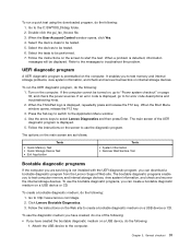
...UEFI diagnostic program, do the following: 1. The options on the screen to select Lenovo Diagnostics and then press Enter. Follow the instructions on the main screen are as follows: Tests • Quick Memory Test • Quick Storage Device Test • Exit Application Tools • System .... Turn on the Web site to be performed. 7. Press the Tab key to switch to http://www.lenovo.com/diags. 2. Go to the Application Menu window. 4. When the ThinkPad logo is displayed. 5. The main screen of the following : 1. Chapter 3. When the Boot Menu window...
...UEFI diagnostic program, do the following: 1. The options on the screen to select Lenovo Diagnostics and then press Enter. Follow the instructions on the main screen are as follows: Tests • Quick Memory Test • Quick Storage Device Test • Exit Application Tools • System .... Turn on the Web site to be performed. 7. Press the Tab key to switch to http://www.lenovo.com/diags. 2. Go to the Application Menu window. 4. When the ThinkPad logo is displayed. 5. The main screen of the following : 1. Chapter 3. When the Boot Menu window...
Hardware Maintenance Manual
Page 47
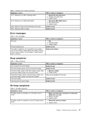
..., pause, one more short beep, pause, and three short beeps Five short beeps One long and two short beeps FRU or action, in sequence 1. Memory module 3. System board Chapter 4. Table 1. Reseat the Mini SATA device. 2. Thermal sensing error. FRU or action, in sequence 1. Fan 2. System ... Error messages Table 2. Error messages Symptom or error Fan error. Please replace the battery with the correct Lenovo battery for this system and will not charge. Beep symptoms Table 3. Memory module 2. No-beep symptoms Symptom or error No beep, power-on indicator on , and LCD blank during...
..., pause, one more short beep, pause, and three short beeps Five short beeps One long and two short beeps FRU or action, in sequence 1. Memory module 3. System board Chapter 4. Table 1. Reseat the Mini SATA device. 2. Thermal sensing error. FRU or action, in sequence 1. Fan 2. System ... Error messages Table 2. Error messages Symptom or error Fan error. Please replace the battery with the correct Lenovo battery for this system and will not charge. Beep symptoms Table 3. Memory module 2. No-beep symptoms Symptom or error No beep, power-on indicator on , and LCD blank during...
Hardware Maintenance Manual
Page 49
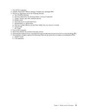
... one at a time until you find the failing FRU. 7. Remove or disconnect all and then install only one memory module) h. External drive or optical drive g. Memory module (Remove all of the following FRUs one at a time (do not replace a nondefective FRU): a. Turn ...on the computer. 5. Determine whether the problem has been solved. 6. Battery pack e. If the problem remains, replace the following devices: a. Non-ThinkPad devices b. Printer, ...
... one at a time until you find the failing FRU. 7. Remove or disconnect all and then install only one memory module) h. External drive or optical drive g. Memory module (Remove all of the following FRUs one at a time (do not replace a nondefective FRU): a. Turn ...on the computer. 5. Determine whether the problem has been solved. 6. Battery pack e. If the problem remains, replace the following devices: a. Non-ThinkPad devices b. Printer, ...
Hardware Maintenance Manual
Page 60
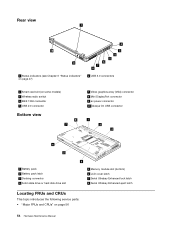
... DisplayPort connector 9 ac power connector 10 Always On USB connector 1 2 3 6 5 1 Battery pack 2 Battery pack latch 3 Docking connector 4 Solid state drive or hard disk drive slot 4 5 Memory module slot (bottom) 6 LCD cover latch 7 Serial Ultrabay Enhanced lock latch 8 Serial Ultrabay Enhanced eject latch Locating FRUs and CRUs This topic introduces the following...
... DisplayPort connector 9 ac power connector 10 Always On USB connector 1 2 3 6 5 1 Battery pack 2 Battery pack latch 3 Docking connector 4 Solid state drive or hard disk drive slot 4 5 Memory module slot (bottom) 6 LCD cover latch 7 Serial Ultrabay Enhanced lock latch 8 Serial Ultrabay Enhanced eject latch Locating FRUs and CRUs This topic introduces the following...
Hardware Maintenance Manual
Page 61
... label, and a container will ship the CRU to find a list of the replacement CRU. ThinkPad computers contain the following types of CRUs include the ac power adapter, power cord, battery, and... designated as optional-service CRUs. Installation of this Hardware Maintenance Manual. See your Lenovo Limited Warranty documentation for your product in this manual can be required to the warranty... upon request. and (2) you can either install the CRU yourself or you might include the memory module, wireless card, keyboard, and palm rest with a replacement part you . For optional-...
... label, and a container will ship the CRU to find a list of the replacement CRU. ThinkPad computers contain the following types of CRUs include the ac power adapter, power cord, battery, and... designated as optional-service CRUs. Installation of this Hardware Maintenance Manual. See your Lenovo Limited Warranty documentation for your product in this manual can be required to the warranty... upon request. and (2) you can either install the CRU yourself or you might include the memory module, wireless card, keyboard, and palm rest with a replacement part you . For optional-...
Hardware Maintenance Manual
Page 63
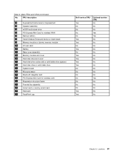
... state drive 6 PCI Express Mini Card for wireless WAN 7 Backup battery 8 Serial Ultrabay Enhanced device or blank bezel 9 Memory module or dummy memory module 10 I/O sub card 11 Battery 12 Base cover assembly 13 Memory module slot cover 14 Hard disk drive slot cover 15 Hard disk drive rubber rails or solid state...
... state drive 6 PCI Express Mini Card for wireless WAN 7 Backup battery 8 Serial Ultrabay Enhanced device or blank bezel 9 Memory module or dummy memory module 10 I/O sub card 11 Battery 12 Base cover assembly 13 Memory module slot cover 14 Hard disk drive slot cover 15 Hard disk drive rubber rails or solid state...
Hardware Maintenance Manual
Page 74
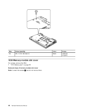
Step NA Screw (quantity) M3 × 5 mm, flat-head (1) 1030 Memory module slot cover For access, remove this FRU: • "1010 Battery pack" on page 66 Removal steps of memory module slot cover Note: Loosen the screws 1 , but do not remove them. Color Black Torque 0.392 Nm (4 kgfcm) 68 Hardware Maintenance Manual
Step NA Screw (quantity) M3 × 5 mm, flat-head (1) 1030 Memory module slot cover For access, remove this FRU: • "1010 Battery pack" on page 66 Removal steps of memory module slot cover Note: Loosen the screws 1 , but do not remove them. Color Black Torque 0.392 Nm (4 kgfcm) 68 Hardware Maintenance Manual
Hardware Maintenance Manual
Page 75
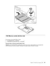
Removing or replacing a FRU 69 Chapter 10. Otherwise, the system might not function correctly. 1 2 1040 Memory module (bottom slot) For access, remove these FRUs in order: • "1010 Battery pack" on page 66 • "1030 Memory module slot cover" on page 68 Removal steps of memory module (bottom slot) Attention: For ThinkPad W530 models that come with two dummy cards installed, do not replace the dummy cards with memory modules.
Removing or replacing a FRU 69 Chapter 10. Otherwise, the system might not function correctly. 1 2 1040 Memory module (bottom slot) For access, remove these FRUs in order: • "1010 Battery pack" on page 66 • "1030 Memory module slot cover" on page 68 Removal steps of memory module (bottom slot) Attention: For ThinkPad W530 models that come with two dummy cards installed, do not replace the dummy cards with memory modules.

Hardware Maintenance Manual
Page 76
...: • Do not drop the drive or apply any physical shock to physical shock. 1 2 1 When installing: Insert the notched end of the memory module into place. Press the memory module firmly, and pivot it until it if possible. • Never remove the drive while the system is operating or is sensitive to...
...: • Do not drop the drive or apply any physical shock to physical shock. 1 2 1 When installing: Insert the notched end of the memory module into place. Press the memory module firmly, and pivot it until it if possible. • Never remove the drive while the system is operating or is sensitive to...
Hardware Maintenance Manual
Page 78
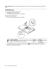
..., wafer-head, nylon-coated (2) Color Black Torque 0.181 Nm (1.85 kgfcm) 2. Press the keyboard in order: • "1010 Battery pack" on page 66 • "1030 Memory module slot cover" on page 68 Removal steps of the keyboard is attached firmly. 1060 Keyboard For access, remove these FRUs in the direction shown...
..., wafer-head, nylon-coated (2) Color Black Torque 0.181 Nm (1.85 kgfcm) 2. Press the keyboard in order: • "1010 Battery pack" on page 66 • "1030 Memory module slot cover" on page 68 Removal steps of the keyboard is attached firmly. 1060 Keyboard For access, remove these FRUs in the direction shown...
Hardware Maintenance Manual
Page 81
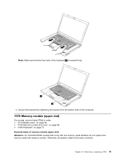
...these FRUs in order: • "1010 Battery pack" on page 66 • "1030 Memory module slot cover" on page 68 • "1060 Keyboard" on page 72 Removal steps of memory module (upper slot) Attention: For ThinkPad W530 models that the front side of the keyboard b is housed firmly. Chapter 10. ...b b 4. Note: Make sure that come with two dummy cards installed, do not replace the dummy cards with memory module.
...these FRUs in order: • "1010 Battery pack" on page 66 • "1030 Memory module slot cover" on page 68 • "1060 Keyboard" on page 72 Removal steps of memory module (upper slot) Attention: For ThinkPad W530 models that the front side of the keyboard b is housed firmly. Chapter 10. ...b b 4. Note: Make sure that come with two dummy cards installed, do not replace the dummy cards with memory module.
Hardware Maintenance Manual
Page 82
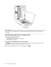
... into place. When installing: Insert the notched end of the arrow. Make sure that it snaps into the socket. Press the memory module firmly, and pivot it until it is firmly installed in the slot and does not move easily. 1080 PCI Express Mini Card for wireless ...LAN For access, remove these FRUs in order: • "1010 Battery pack" on page 66 • "1030 Memory module slot cover" on page 68 • "1060 Keyboard" on page 72 Removal steps of PCI Express Mini Card for wireless LAN In step 1 , unplug...
... into place. When installing: Insert the notched end of the arrow. Make sure that it snaps into the socket. Press the memory module firmly, and pivot it until it is firmly installed in the slot and does not move easily. 1080 PCI Express Mini Card for wireless ...LAN For access, remove these FRUs in order: • "1010 Battery pack" on page 66 • "1030 Memory module slot cover" on page 68 • "1060 Keyboard" on page 72 Removal steps of PCI Express Mini Card for wireless LAN In step 1 , unplug...
Hardware Maintenance Manual
Page 84
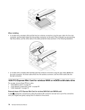
... Card for wireless WAN or mSATA solid state drive For access, remove these FRUs in order: • "1010 Battery pack" on page 66 • "1030 Memory module slot cover" on page 68 • "1060 Keyboard" on the card.
... Card for wireless WAN or mSATA solid state drive For access, remove these FRUs in order: • "1010 Battery pack" on page 66 • "1030 Memory module slot cover" on page 68 • "1060 Keyboard" on the card.
Hardware Maintenance Manual
Page 89
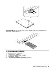
1 2 When installing: Make sure that the ExpressCard blank bezel or ExpressCard is correctly oriented as shown in the following illustration. 1110 Keyboard bezel assembly For access, remove these FRUs in order: • "1010 Battery pack" on page 66 • "1030 Memory module slot cover" on page 68 • "1060 Keyboard" on page 72 • "1100 ExpressCard blank bezel or ExpressCard" on page 82 Chapter 10. Removing or replacing a FRU 83
1 2 When installing: Make sure that the ExpressCard blank bezel or ExpressCard is correctly oriented as shown in the following illustration. 1110 Keyboard bezel assembly For access, remove these FRUs in order: • "1010 Battery pack" on page 66 • "1030 Memory module slot cover" on page 68 • "1060 Keyboard" on page 72 • "1100 ExpressCard blank bezel or ExpressCard" on page 82 Chapter 10. Removing or replacing a FRU 83
Hardware Maintenance Manual
Page 92
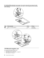
For ThinkPad W530 models with a color sensor, if you need to remove the color sensor from the failing keyboard bezel assembly and install the color sensor to the new keyboard bezel assembly, do the following: 3 3 4 1 2 Step 3 Screw (quantity) M2 × L7 mm, bind-head, (2) 1 Color Silver Torque 0.181 Nm (1.85 kgfcm) 4 4 3 2 1120 Bluetooth daughter card For access, remove these FRUs in order: • "1010 Battery pack" on page 66 • "1030 Memory module slot cover" on page 68 • "1060 Keyboard" on page 72 86 Hardware Maintenance Manual
For ThinkPad W530 models with a color sensor, if you need to remove the color sensor from the failing keyboard bezel assembly and install the color sensor to the new keyboard bezel assembly, do the following: 3 3 4 1 2 Step 3 Screw (quantity) M2 × L7 mm, bind-head, (2) 1 Color Silver Torque 0.181 Nm (1.85 kgfcm) 4 4 3 2 1120 Bluetooth daughter card For access, remove these FRUs in order: • "1010 Battery pack" on page 66 • "1030 Memory module slot cover" on page 68 • "1060 Keyboard" on page 72 86 Hardware Maintenance Manual
Hardware Maintenance Manual
Page 93
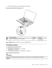
... that the connector is attached firmly. 1130 Backup battery For access, remove these FRUs in order: • "1010 Battery pack" on page 66 • "1030 Memory module slot cover" on page 68 • "1060 Keyboard" on page 72 • "1100 ExpressCard blank bezel or ExpressCard" on page 82 Removal steps of...
... that the connector is attached firmly. 1130 Backup battery For access, remove these FRUs in order: • "1010 Battery pack" on page 66 • "1030 Memory module slot cover" on page 68 • "1060 Keyboard" on page 72 • "1100 ExpressCard blank bezel or ExpressCard" on page 82 Removal steps of...
Hardware Maintenance Manual
Page 94
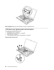
When installing: Make sure that the battery connector is attached firmly. 1140 Smart card, dummy smart card and spacer For access, remove these FRUs in order: • "1010 Battery pack" on page 66 • "1030 Memory module slot cover" on page 68 • "1060 Keyboard" on page 72 • "1100 ExpressCard blank bezel or ExpressCard" on page 82 Removal steps of smart card 33 3 4 1 2 88 Hardware Maintenance Manual
When installing: Make sure that the battery connector is attached firmly. 1140 Smart card, dummy smart card and spacer For access, remove these FRUs in order: • "1010 Battery pack" on page 66 • "1030 Memory module slot cover" on page 68 • "1060 Keyboard" on page 72 • "1100 ExpressCard blank bezel or ExpressCard" on page 82 Removal steps of smart card 33 3 4 1 2 88 Hardware Maintenance Manual


