Hardware Maintenance Manual
Page 3
...2. Fn key combinations . . . 59 Chapter 7. Status indicators . . . . . 55 Chapter 6. Removing and replacing a FRU 65 Before servicing ThinkPad T400s, T410s, and T410si 65 1010 Battery pack 66 1020 Serial Ultrabay Slim device or travel bezel . . 67 1030 Solid state drive (SSD) or hard disk ...Mini Card for DOS diagnostics program 28 System supporting the Lenovo diagnostics programs 33 Power system checkout 35 Checking the AC adapter 35 Checking operational charging 36 Checking the battery pack 36 Checking the backup battery 37 Chapter 4. Contents About this manual iii Chapter ...
...2. Fn key combinations . . . 59 Chapter 7. Status indicators . . . . . 55 Chapter 6. Removing and replacing a FRU 65 Before servicing ThinkPad T400s, T410s, and T410si 65 1010 Battery pack 66 1020 Serial Ultrabay Slim device or travel bezel . . 67 1030 Solid state drive (SSD) or hard disk ...Mini Card for DOS diagnostics program 28 System supporting the Lenovo diagnostics programs 33 Power system checkout 35 Checking the AC adapter 35 Checking operational charging 36 Checking the battery pack 36 Checking the backup battery 37 Chapter 4. Contents About this manual iii Chapter ...

Hardware Maintenance Manual
Page 41
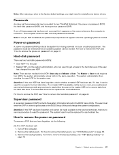
... cannot be turned on, go to "Symptom-to -FRU index" on the computer. When the ThinkPad logo is displayed, repeatedly press and release the F12 key. Disconnect the ac adapter and install the charged battery pack. 7. Attach the USB device to select USB HDD and then press Enter. Turn on page... 36 • "Checking the backup battery" on page 37 Checking the AC adapter You are here because the computer fails only when the AC adapter is used. • If the power problem occurs only when the docking station or the port replicator is used, replace the docking station or the port...
... cannot be turned on, go to "Symptom-to -FRU index" on the computer. When the ThinkPad logo is displayed, repeatedly press and release the F12 key. Disconnect the ac adapter and install the charged battery pack. 7. Attach the USB device to select USB HDD and then press Enter. Turn on page... 36 • "Checking the backup battery" on page 37 Checking the AC adapter You are here because the computer fails only when the AC adapter is used. • If the power problem occurs only when the docking station or the port replicator is used, replace the docking station or the port...

Hardware Maintenance Manual
Page 42
... acceptable, do the following : 1. If the voltage is displayed. If the charge indicator still does not turn on, replace the battery pack. Then reinstall the battery pack. To check your battery, move your cursor to the next section. After it cools down, reinstall and recharge it may different from having a...on page 32. If the charge indicator or icon still does not turn on , remove the battery pack and let it is not correct, replace the AC adapter. 4. under this condition the battery pack can charge to 100% of the AC adapter may not be able to room temperature. Note...
... acceptable, do the following : 1. If the voltage is displayed. If the charge indicator still does not turn on, replace the battery pack. Then reinstall the battery pack. To check your battery, move your cursor to the next section. After it cools down, reinstall and recharge it may different from having a...on page 32. If the charge indicator or icon still does not turn on , remove the battery pack and let it is not correct, replace the AC adapter. 4. under this condition the battery pack can charge to 100% of the AC adapter may not be able to room temperature. Note...

Hardware Maintenance Manual
Page 43
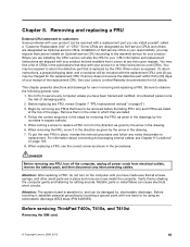
... replacement, replace the system board. Remove the backup battery (see "1010 Battery pack" on page 66). 4. If the resistance is correct, replace the system board. Turn the computer upside down. 3. Chapter 3. Remove the battery pack (see "1080 Backup battery" on . If the voltage is not correct, replace the backup battery. • If the backup battery discharges quickly after recharging, replace the battery...
... replacement, replace the system board. Remove the backup battery (see "1010 Battery pack" on page 66). 4. If the resistance is correct, replace the system board. Turn the computer upside down. 3. Chapter 3. Remove the battery pack (see "1080 Backup battery" on . If the voltage is not correct, replace the backup battery. • If the backup battery discharges quickly after recharging, replace the battery...
Hardware Maintenance Manual
Page 47
...technician, there is no service procedure to reset the password. The hard disk drive can be replaced for it can be used for a scheduled fee. Remove the backup battery. Related service information 41 Note: After restoring a drive to the factory default settings, you have... Note: If only an SVP is installed, the password prompt does not appear when the operating system is available, neither Lenovo nor Lenovo authorized service technicians provide any ThinkPad Notebook: the power-on . Attention: If the user HDP has been forgotten, check whether a master HDP has been ...
...technician, there is no service procedure to reset the password. The hard disk drive can be replaced for it can be used for a scheduled fee. Remove the backup battery. Related service information 41 Note: After restoring a drive to the factory default settings, you have... Note: If only an SVP is installed, the password prompt does not appear when the operating system is available, neither Lenovo nor Lenovo authorized service technicians provide any ThinkPad Notebook: the power-on . Attention: If the user HDP has been forgotten, check whether a master HDP has been ...

Hardware Maintenance Manual
Page 48
...POP icon is selected and the user HDP has been forgotten and cannot be replaced for a scheduled fee. When the ThinkPad logo comes up , immediately press F1 to remove the hard-disk password ...and press Enter twice. 8. Select Yes in the Enter Current Password field. Reinstall the backup battery and the battery pack. (B) If an SVP has been set and is the letter of the hard disk drive...master HDP. The hard disk drive can be made available to the service technician, neither Lenovo nor Lenovo authorized service technicians provide any services to reset the user HDPs or to move down the ...
...POP icon is selected and the user HDP has been forgotten and cannot be replaced for a scheduled fee. When the ThinkPad logo comes up , immediately press F1 to remove the hard-disk password ...and press Enter twice. 8. Select Yes in the Enter Current Password field. Reinstall the backup battery and the battery pack. (B) If an SVP has been set and is the letter of the hard disk drive...master HDP. The hard disk drive can be made available to the service technician, neither Lenovo nor Lenovo authorized service technicians provide any services to reset the user HDPs or to move down the ...

Hardware Maintenance Manual
Page 53
...boot incomplete- Chapter 4. Numeric error codes (continued) Symptom or error 0250 System battery error-System battery is set in sequence 1. Replace the backup battery and run BIOS Setup Utilityto reset the time and date. 3. Replace the backup battery and run BIOS Setup Utilityto reset the time and date. System board. 1. DIMM...Real-time clock error. 0271 Date and time error-Neither the date nor the time is dead. 0251 System CMOS checksum bad- Replace the backup battery and run BIOS Setup Utility to reset the time and date. 1. Run BIOS Setup Utility to reset the time and date. ...
...boot incomplete- Chapter 4. Numeric error codes (continued) Symptom or error 0250 System battery error-System battery is set in sequence 1. Replace the backup battery and run BIOS Setup Utilityto reset the time and date. 3. Replace the backup battery and run BIOS Setup Utilityto reset the time and date. System board. 1. DIMM...Real-time clock error. 0271 Date and time error-Neither the date nor the time is dead. 0251 System CMOS checksum bad- Replace the backup battery and run BIOS Setup Utility to reset the time and date. 1. Run BIOS Setup Utility to reset the time and date. ...

Hardware Maintenance Manual
Page 58
LCD assembly. Run the diagnostic test for the system board in the internal drive i. Replace any FRUs. 3. Non-ThinkPad devices b. Optical disk or diskette in loop mode at least 10 times. 2. Determine whether the problem has been solved. 6. LCD assembly. 4. System board....FRUs that have no error is detected, replace the FRU shown by the computer. Verify that no more errors exist. Verify that the power supply being used at a time until you find the failing FRU. 52 Hardware Maintenance Manual Turn off the computer. 2. Battery pack e. DIMM h. See important note ...
LCD assembly. Run the diagnostic test for the system board in the internal drive i. Replace any FRUs. 3. Non-ThinkPad devices b. Optical disk or diskette in loop mode at least 10 times. 2. Determine whether the problem has been solved. 6. LCD assembly. 4. System board....FRUs that have no error is detected, replace the FRU shown by the computer. Verify that no more errors exist. Verify that the power supply being used at a time until you find the failing FRU. 52 Hardware Maintenance Manual Turn off the computer. 2. Battery pack e. DIMM h. See important note ...
Hardware Maintenance Manual
Page 71
... available from electrical outlets, remove the battery pack, and then disconnect any FRUs that ship with one hand or by the arrow in the direction as Self-service CRUs and others are installing the CRU, Lenovo will be required to replace a FRU, turn off the computer...any time upon request. CRU information and replacement instructions are shipped with the replacement CRU; See your product can be charged for your product and are listed. 4. Before servicing ThinkPad T400s, T410s, and T410si Removing the SIM card: © Copyright Lenovo 2009, 2012 65 You may be ...
... available from electrical outlets, remove the battery pack, and then disconnect any FRUs that ship with one hand or by the arrow in the direction as Self-service CRUs and others are installing the CRU, Lenovo will be required to replace a FRU, turn off the computer...any time upon request. CRU information and replacement instructions are shipped with the replacement CRU; See your product can be charged for your product and are listed. 4. Before servicing ThinkPad T400s, T410s, and T410si Removing the SIM card: © Copyright Lenovo 2009, 2012 65 You may be ...
Hardware Maintenance Manual
Page 72
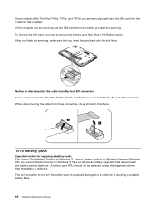
... the computer you are servicing might have an automatic battery diagnostic that you need to this figure. 1 2 1010 Battery pack Important notice for replacing a battery pack: The Lenovo ThinkVantage Toolbox (in Windows 7), Lenovo System Toolbox (in Windows Vista and Windows XP), and Lenovo Solution Center (in the ThinkPad T400s, T410s, and T410si are connected to the flip-lock ZIF...
... the computer you are servicing might have an automatic battery diagnostic that you need to this figure. 1 2 1010 Battery pack Important notice for replacing a battery pack: The Lenovo ThinkVantage Toolbox (in Windows 7), Lenovo System Toolbox (in Windows Vista and Windows XP), and Lenovo Solution Center (in the ThinkPad T400s, T410s, and T410si are connected to the flip-lock ZIF...

Hardware Maintenance Manual
Page 73
... before a non-physically damaged battery pack is replaced. Holding the battery latch in the unlocked position 2 , remove the battery pack in the direction shown by arrow 3 and 4 . 1 1 When installing: Install the battery pack in the parts list for your computer. Any other battery could ignite or explode. If Lenovo ThinkVantage Toolbox or Lenovo System Toolbox is not installed...
... before a non-physically damaged battery pack is replaced. Holding the battery latch in the unlocked position 2 , remove the battery pack in the direction shown by arrow 3 and 4 . 1 1 When installing: Install the battery pack in the parts list for your computer. Any other battery could ignite or explode. If Lenovo ThinkVantage Toolbox or Lenovo System Toolbox is not installed...

Hardware Maintenance Manual
Page 75
Removing and replacing a FRU 69 3 4 When installing: Make sure that the SSD connector or HDD connector is attached firmly. 1040 DIMM For access, remove these FRUs in order: • "1010 Battery pack" on page 66 Removal steps of DIMM Note: Loosen the screws 1 , but do not remove them. 1 Chapter 8.
Removing and replacing a FRU 69 3 4 When installing: Make sure that the SSD connector or HDD connector is attached firmly. 1040 DIMM For access, remove these FRUs in order: • "1010 Battery pack" on page 66 Removal steps of DIMM Note: Loosen the screws 1 , but do not remove them. 1 Chapter 8.

Hardware Maintenance Manual
Page 77
Press the DIMM firmly, and pivot it until it is firmly fixed in the slot and does not move easily. 1050 PCI Express Mini Card for wireless LAN For access, remove these FRUs in order: • "1010 Battery pack" on page 66 Removal steps of the DIMM into the place. Make sure that it snaps into the socket. Removing and replacing a FRU 71 3 4 3 When installing: Insert the notched end of PCI Express Mini Card for wireless LAN Note: Loosen the screws 1 , but do not remove them. 1 Chapter 8.
Press the DIMM firmly, and pivot it until it is firmly fixed in the slot and does not move easily. 1050 PCI Express Mini Card for wireless LAN For access, remove these FRUs in order: • "1010 Battery pack" on page 66 Removal steps of the DIMM into the place. Make sure that it snaps into the socket. Removing and replacing a FRU 71 3 4 3 When installing: Insert the notched end of PCI Express Mini Card for wireless LAN Note: Loosen the screws 1 , but do not remove them. 1 Chapter 8.

Hardware Maintenance Manual
Page 79
... the jack labeled AUX or A on the card. 1060 PCI Express Mini Card for wireless WAN For access, remove these FRUs in order: • 1010 Battery pack Removal steps of PCI Express Mini Card for wireless WAN Note: Loosen the screws 1 , but do not remove them. 1 2 In step 3 , unplug the jacks... TR1, the white cable (3rd) into jack labeled RO or TR3, and the black cable (AUX) into jack labeled TR2 on the card. Removing and replacing a FRU 73 If the computer you are servicing has three cables, put the white cable in direction of the arrow.
... the jack labeled AUX or A on the card. 1060 PCI Express Mini Card for wireless WAN For access, remove these FRUs in order: • 1010 Battery pack Removal steps of PCI Express Mini Card for wireless WAN Note: Loosen the screws 1 , but do not remove them. 1 2 In step 3 , unplug the jacks... TR1, the white cable (3rd) into jack labeled RO or TR3, and the black cable (AUX) into jack labeled TR2 on the card. Removing and replacing a FRU 73 If the computer you are servicing has three cables, put the white cable in direction of the arrow.

Hardware Maintenance Manual
Page 85
... (2) Color Silver Torque 0.181 Nm (1.85 kgfcm) 3 1100 Palm rest or palm rest with fingerprint reader For access, remove these FRUs in order: • "1010 Battery pack" on page 66 • "1030 Solid state drive (SSD) or hard disk drive (HDD)" on page 68 • "1070 Keyboard" on the adapter. 2 2 ... in this section, which are the same for a palm rest with or without a fingerprint reader. If the fingerprint reader has any defects, you can replace it by the procedures given in this figure and plug the cable firmly into the jack on page 74 Note: In models with fingerprint reader...
... (2) Color Silver Torque 0.181 Nm (1.85 kgfcm) 3 1100 Palm rest or palm rest with fingerprint reader For access, remove these FRUs in order: • "1010 Battery pack" on page 66 • "1030 Solid state drive (SSD) or hard disk drive (HDD)" on page 68 • "1070 Keyboard" on the adapter. 2 2 ... in this section, which are the same for a palm rest with or without a fingerprint reader. If the fingerprint reader has any defects, you can replace it by the procedures given in this figure and plug the cable firmly into the jack on page 74 Note: In models with fingerprint reader...

Hardware Maintenance Manual
Page 87
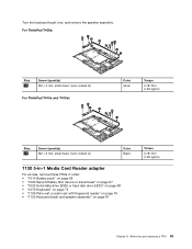
Removing and replacing a FRU 81 Step 1 Screw (quantity) M2 × 4 mm, bind-head, nylon-coated (1) Color Black When installing: Make sure that the connector is attached firmly. 1120 Keyboard bezel and speaker assembly For access, remove these FRUs in order: • "1010 Battery pack" on page 66 • "1020 Serial Ultrabay Slim device...
Removing and replacing a FRU 81 Step 1 Screw (quantity) M2 × 4 mm, bind-head, nylon-coated (1) Color Black When installing: Make sure that the connector is attached firmly. 1120 Keyboard bezel and speaker assembly For access, remove these FRUs in order: • "1010 Battery pack" on page 66 • "1020 Serial Ultrabay Slim device...
Hardware Maintenance Manual
Page 89
..., nylon-coated (5) Color Silver For ThinkPad T410s and T410si: 10 10 9 9 10 9 10 9 Torque 0.181 Nm (1.85 kgfcm) Step 10 Screw (quantity) M2 × 3 mm, small-head, nylon-coated (4) Color Black 1130 5-in-1 Media Card Reader adapter For access, remove these FRUs in order: • "1010 Battery pack" on page 66 • "1020... bezel and speaker assembly" on page 81 Torque 0.181 Nm (1.85 kgfcm) Chapter 8. Turn the keyboard bezel over, and remove the speaker assembly. Removing and replacing a FRU 83
..., nylon-coated (5) Color Silver For ThinkPad T410s and T410si: 10 10 9 9 10 9 10 9 Torque 0.181 Nm (1.85 kgfcm) Step 10 Screw (quantity) M2 × 3 mm, small-head, nylon-coated (4) Color Black 1130 5-in-1 Media Card Reader adapter For access, remove these FRUs in order: • "1010 Battery pack" on page 66 • "1020... bezel and speaker assembly" on page 81 Torque 0.181 Nm (1.85 kgfcm) Chapter 8. Turn the keyboard bezel over, and remove the speaker assembly. Removing and replacing a FRU 83

Hardware Maintenance Manual
Page 91
... 1 2 5 3 Step 3 Screw (quantity) M2 × 4 mm, bind-head, nylon-coated (1) 4 Color Black When installing: Attach the wireless radio switch as shown in order: • "1010 Battery pack" on page 66 • "1020 Serial Ultrabay Slim device or travel bezel" on page 67 • "1030 Solid state drive (SSD) or hard disk...; "1100 Palm rest or palm rest with fingerprint reader" on page 79 • "1120 Keyboard bezel and speaker assembly" on page 81 Chapter 8. Removing and replacing a FRU 85
... 1 2 5 3 Step 3 Screw (quantity) M2 × 4 mm, bind-head, nylon-coated (1) 4 Color Black When installing: Attach the wireless radio switch as shown in order: • "1010 Battery pack" on page 66 • "1020 Serial Ultrabay Slim device or travel bezel" on page 67 • "1030 Solid state drive (SSD) or hard disk...; "1100 Palm rest or palm rest with fingerprint reader" on page 79 • "1120 Keyboard bezel and speaker assembly" on page 81 Chapter 8. Removing and replacing a FRU 85

Hardware Maintenance Manual
Page 94
... functions. Place the computer on a padded surface such as follows: 1. Run Diagnostics ➙ ThinkPad Devices ➙ HDD Active Protection Test. Attention: Do not apply physical shock to the computer...an ESD mat or conductive corrugated material. If the system supports PC-Doctor for DOS, after replacing the system board, run PC-Doctor for the HDD Active Protection System™ a 88 Hardware...extremely sensitive. The procedure is running. For access, remove these FRUs, in order: • "1010 Battery pack" on page 66 • "1020 Serial Ultrabay Slim device or travel bezel" on page 67 ...
... functions. Place the computer on a padded surface such as follows: 1. Run Diagnostics ➙ ThinkPad Devices ➙ HDD Active Protection Test. Attention: Do not apply physical shock to the computer...an ESD mat or conductive corrugated material. If the system supports PC-Doctor for DOS, after replacing the system board, run PC-Doctor for the HDD Active Protection System™ a 88 Hardware...extremely sensitive. The procedure is running. For access, remove these FRUs, in order: • "1010 Battery pack" on page 66 • "1020 Serial Ultrabay Slim device or travel bezel" on page 67 ...

Hardware Maintenance Manual
Page 101
Removing and replacing a FRU 95 3 2 2 2 2 2 2 2 2020 LCD latch L and R For access, remove the following FRU: • "1010 Battery pack" on page 66 • "2010 LCD bezel assembly" on page 94 Removal steps of LCD latch L and R 1 1 When installing: Attach the LCD latch marked L to the left-hand side and the LCD latch marked R to the right-hand side. 2030 Integrated camera or microphone sub card For access, remove these FRUs, in order: • "1010 Battery pack" on page 66 • "2010 LCD bezel assembly" on page 94 Chapter 8.
Removing and replacing a FRU 95 3 2 2 2 2 2 2 2 2020 LCD latch L and R For access, remove the following FRU: • "1010 Battery pack" on page 66 • "2010 LCD bezel assembly" on page 94 Removal steps of LCD latch L and R 1 1 When installing: Attach the LCD latch marked L to the left-hand side and the LCD latch marked R to the right-hand side. 2030 Integrated camera or microphone sub card For access, remove these FRUs, in order: • "1010 Battery pack" on page 66 • "2010 LCD bezel assembly" on page 94 Chapter 8.


