
Hardware Maintenance Manual
Page 6
... SL500c 122 2010 LCD front bezel 125 2020 Inverter card or LED control card . . . . 126 2030 Integrated camera 128 2040 Wireless LAN antenna assembly, wireless WAN antenna assembly, and camera cable (for ThinkPad SL500 and 500c) . . 145 Parts list 146 Overall 147 LCD FRUs 190 Keyboard 214 Miscellaneous parts 215 AC adapters 216 Power cords...
... SL500c 122 2010 LCD front bezel 125 2020 Inverter card or LED control card . . . . 126 2030 Integrated camera 128 2040 Wireless LAN antenna assembly, wireless WAN antenna assembly, and camera cable (for ThinkPad SL500 and 500c) . . 145 Parts list 146 Overall 147 LCD FRUs 190 Keyboard 214 Miscellaneous parts 215 AC adapters 216 Power cords...

Hardware Maintenance Manual
Page 136
2030 Integrated camera For access, remove these FRUs in order: v "1010 Battery pack" on page 63 v "2010 LCD front bezel" on page 125 Note: Some models do not have the integrated camera. Table 49. Removal steps of integrated camera 3 2 1 When installing: Make sure that the connector is attached firmly. 128 ThinkPad SL400, SL400c, SL500, and SL500c Hardware Maintenance Manual
2030 Integrated camera For access, remove these FRUs in order: v "1010 Battery pack" on page 63 v "2010 LCD front bezel" on page 125 Note: Some models do not have the integrated camera. Table 49. Removal steps of integrated camera 3 2 1 When installing: Make sure that the connector is attached firmly. 128 ThinkPad SL400, SL400c, SL500, and SL500c Hardware Maintenance Manual

Hardware Maintenance Manual
Page 137
ThinkPad SL400, SL400c, SL500, and SL500c 129 Tension could cause the cables to be damaged by the cable guides, or a wire to any tension. 2040 Wireless LAN antenna assembly, wireless WAN antenna assembly, and camera cable (for ThinkPad SL400 and SL400c) For access, remove these FRUs in order: v "1010 Battery ...1220 Top case sub assembly (for ThinkPad SL400 and SL400c)" on page 95 v "1240 LCD unit (for ThinkPad SL400 and SL400c)" on page 100 v "2010 LCD front bezel" on page 125 v "2020 Inverter card or LED control card" on page 126 v "2030 Integrated camera" on page 128 Table 50. Removal...
ThinkPad SL400, SL400c, SL500, and SL500c 129 Tension could cause the cables to be damaged by the cable guides, or a wire to any tension. 2040 Wireless LAN antenna assembly, wireless WAN antenna assembly, and camera cable (for ThinkPad SL400 and SL400c) For access, remove these FRUs in order: v "1010 Battery ...1220 Top case sub assembly (for ThinkPad SL400 and SL400c)" on page 95 v "1240 LCD unit (for ThinkPad SL400 and SL400c)" on page 100 v "2010 LCD front bezel" on page 125 v "2020 Inverter card or LED control card" on page 126 v "2030 Integrated camera" on page 128 Table 50. Removal...

Hardware Maintenance Manual
Page 139
...1 1 1 When installing: As you route the cables, make sure that they are not subjected to be broken. ThinkPad SL400, SL400c, SL500, and SL500c 131 wireless WAN antenna assembly, and camera cable (for ThinkPad SL500 and SL500c) For access, remove these FRUs in order: v "1010 Battery pack" on page 63 v "1020...93 v "1230 Top case sub assembly (for ThinkPad SL500)" on page 97 v "1250 LCD unit (for ThinkPad SL500 and SL500c)" on page 105 v "2010 LCD front bezel" on page 125 v "2020 Inverter card or LED control card" on page 126 v "2030 Integrated camera" on page 128 Table 52. 2050 Wireless LAN ...
...1 1 1 When installing: As you route the cables, make sure that they are not subjected to be broken. ThinkPad SL400, SL400c, SL500, and SL500c 131 wireless WAN antenna assembly, and camera cable (for ThinkPad SL500 and SL500c) For access, remove these FRUs in order: v "1010 Battery pack" on page 63 v "1020...93 v "1230 Top case sub assembly (for ThinkPad SL500)" on page 97 v "1250 LCD unit (for ThinkPad SL500 and SL500c)" on page 105 v "2010 LCD front bezel" on page 125 v "2020 Inverter card or LED control card" on page 126 v "2030 Integrated camera" on page 128 Table 52. 2050 Wireless LAN ...

Hardware Maintenance Manual
Page 141
... on page 125 v "2020 Inverter card or LED control card" on page 126 v "2030 Integrated camera" on page 128 v "2040 Wireless LAN antenna assembly, wireless WAN antenna assembly, and camera cable (for ThinkPad SL400 and SL400c)" on page 129 Table 54. Removal steps of LCD panel and LCD cable ...1 1 Step 1 Screw (quantity) Color M2.5 × 5 mm, wafer-head, nylon-coated (2) Black Torque 0.392 Nm (4 kgfcm) ThinkPad SL400, SL400c, SL500, and SL500c 133
... on page 125 v "2020 Inverter card or LED control card" on page 126 v "2030 Integrated camera" on page 128 v "2040 Wireless LAN antenna assembly, wireless WAN antenna assembly, and camera cable (for ThinkPad SL400 and SL400c)" on page 129 Table 54. Removal steps of LCD panel and LCD cable ...1 1 Step 1 Screw (quantity) Color M2.5 × 5 mm, wafer-head, nylon-coated (2) Black Torque 0.392 Nm (4 kgfcm) ThinkPad SL400, SL400c, SL500, and SL500c 133

Hardware Maintenance Manual
Page 144
... unit (for ThinkPad SL500 and SL500c)" on page 128 v "2050 Wireless LAN antenna assembly. wireless WAN antenna assembly, and camera cable (for ThinkPad SL500 and SL500c)" on page 105 v "2010 LCD front bezel" on page 125 v "2020 Inverter card or LED control card" on page 126 v "2030 Integrated camera" on page 131 136 ThinkPad SL400, SL400c, SL500, and SL500c...
... unit (for ThinkPad SL500 and SL500c)" on page 128 v "2050 Wireless LAN antenna assembly. wireless WAN antenna assembly, and camera cable (for ThinkPad SL500 and SL500c)" on page 105 v "2010 LCD front bezel" on page 125 v "2020 Inverter card or LED control card" on page 126 v "2030 Integrated camera" on page 131 136 ThinkPad SL400, SL400c, SL500, and SL500c...

Hardware Maintenance Manual
Page 147
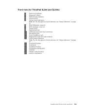
Locations Front view (for ThinkPad SL400 and SL400c) 1 Built-in microphone 2 Integrated camera 3 Built-in stereo speakers 4 Power switch 5 System status indicators Note: For the description of each indicator, see "Status indicators" on page 52. 6 RJ-45 (Ethernet) ... indicators" on page 52. 15 Touch pad buttons 16 Touch pad 17 TrackPoint buttons 18 TrackPoint pointing stick 19 UltraNav 20 Volume control buttons 21 Lenovo CareSM button ThinkPad SL400, SL400c, SL500, and SL500c 139
Locations Front view (for ThinkPad SL400 and SL400c) 1 Built-in microphone 2 Integrated camera 3 Built-in stereo speakers 4 Power switch 5 System status indicators Note: For the description of each indicator, see "Status indicators" on page 52. 6 RJ-45 (Ethernet) ... indicators" on page 52. 15 Touch pad buttons 16 Touch pad 17 TrackPoint buttons 18 TrackPoint pointing stick 19 UltraNav 20 Volume control buttons 21 Lenovo CareSM button ThinkPad SL400, SL400c, SL500, and SL500c 139
Hardware Maintenance Manual
Page 151
Front view (for ThinkPad SL500 and SL500c) 1 Built-in microphone 2 Integrated camera 3 Built-in stereo speakers 4 Power switch 5 System status indicators Note: For the description of each indicator, see "Status indicators" on page 52. 6 RJ-45 (Ethernet) ... indicators" on page 52. 15 Touch pad buttons 16 Touch pad 17 TrackPoint buttons 18 TrackPoint pointing stick 19 UltraNav 20 Volume control buttons 21 Lenovo Care button ThinkPad SL400, SL400c, SL500, and SL500c 143
Front view (for ThinkPad SL500 and SL500c) 1 Built-in microphone 2 Integrated camera 3 Built-in stereo speakers 4 Power switch 5 System status indicators Note: For the description of each indicator, see "Status indicators" on page 52. 6 RJ-45 (Ethernet) ... indicators" on page 52. 15 Touch pad buttons 16 Touch pad 17 TrackPoint buttons 18 TrackPoint pointing stick 19 UltraNav 20 Volume control buttons 21 Lenovo Care button ThinkPad SL400, SL400c, SL500, and SL500c 143
(English) Setup Guide
Page 1
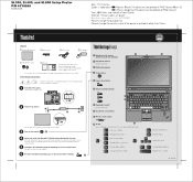
... you want to move the pointer. For more detailed information, press the Lenovo CareSM button: 5 1 UltraConnectTM wireless antennas (main and auxiliary) 2 Integrated camera* *Select models only. 3 Built-in microphone 4 Power button 5 Lenovo Care button 1 1 2 3 3 6 Volume and mute buttons 7 ... 7 Manage external devices Enter hibernation Multimedia controls Change display brightness Magnify screen contents P/N: 43Y6268 43Y6268 05/08/2008 Unpack ThinkPad notebook Battery pack Power cord AC adapter 2 TrackPoint caps Manuals - Setup Instructions (this sheet) - Install battery pack...
... you want to move the pointer. For more detailed information, press the Lenovo CareSM button: 5 1 UltraConnectTM wireless antennas (main and auxiliary) 2 Integrated camera* *Select models only. 3 Built-in microphone 4 Power button 5 Lenovo Care button 1 1 2 3 3 6 Volume and mute buttons 7 ... 7 Manage external devices Enter hibernation Multimedia controls Change display brightness Magnify screen contents P/N: 43Y6268 43Y6268 05/08/2008 Unpack ThinkPad notebook Battery pack Power cord AC adapter 2 TrackPoint caps Manuals - Setup Instructions (this sheet) - Install battery pack...
(English) Setup Guide
Page 2
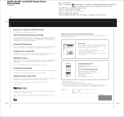
... in the Service and Troubleshooting Guide. Copyright Lenovo 2008. Complete device connectivity Device ports and connectors, such as an integrated camera*, a VibrantView LCD display*, an HDMI (High-Definition Multimedia Interface) port, and an integrated Blu-ray, Multi-burner, or Combo drive... large hard drives (capable of storing vast music, video, and picture collections), and other countries, or both: Lenovo Lenovo Care ThinkPad ThinkVantage TrackPoint UltraConnect UltraNav Other company, product, or service names may contain items that are advanced technologies that provides...
... in the Service and Troubleshooting Guide. Copyright Lenovo 2008. Complete device connectivity Device ports and connectors, such as an integrated camera*, a VibrantView LCD display*, an HDMI (High-Definition Multimedia Interface) port, and an integrated Blu-ray, Multi-burner, or Combo drive... large hard drives (capable of storing vast music, video, and picture collections), and other countries, or both: Lenovo Lenovo Care ThinkPad ThinkVantage TrackPoint UltraConnect UltraNav Other company, product, or service names may contain items that are advanced technologies that provides...
Hardware Maintenance Manual
Page 6
... assembly), I/O board, I/O board FPC, DC-in connector, small board, and base cover (for ThinkPad SL500 122 2010 LCD front bezel 125 2020 Inverter card 126 2030 Integrated camera 127 2040 Wireless LAN antenna assembly, wireless WAN antenna assembly, and camera cable (for ThinkPad SL500) . . . . . 144 Parts list 145 Overall 146 LCD FRUs 157 Keyboard 166 Miscellaneous parts...
... assembly), I/O board, I/O board FPC, DC-in connector, small board, and base cover (for ThinkPad SL500 122 2010 LCD front bezel 125 2020 Inverter card 126 2030 Integrated camera 127 2040 Wireless LAN antenna assembly, wireless WAN antenna assembly, and camera cable (for ThinkPad SL500) . . . . . 144 Parts list 145 Overall 146 LCD FRUs 157 Keyboard 166 Miscellaneous parts...

Hardware Maintenance Manual
Page 135
2030 Integrated camera For access, remove these FRUs in order: v "1010 Battery pack" on page 63 v "2010 LCD front bezel" on page 125 Note: Some models do not have the integrated camera. ThinkPad SL400 and SL500 127 Removal steps of integrated camera 3 2 1 When installing: Make sure that the connector is attached firmly. Table 49.
2030 Integrated camera For access, remove these FRUs in order: v "1010 Battery pack" on page 63 v "2010 LCD front bezel" on page 125 Note: Some models do not have the integrated camera. ThinkPad SL400 and SL500 127 Removal steps of integrated camera 3 2 1 When installing: Make sure that the connector is attached firmly. Table 49.

Hardware Maintenance Manual
Page 136
... on page 93 v "1220 Top case sub assembly (for ThinkPad SL400)" on page 95 v "1240 LCD unit (for ThinkPad SL400)" on page 100 v "2010 LCD front bezel" on page 125 v "2020 Inverter card" on page 126 v "2030 Integrated camera" on page 127 Table 50. Removal steps of antenna assemblies ...and camera cable 1 1 1 1 1 When installing: As you route the cables, make sure that they are not subjected to be broken. 128 ThinkPad SL400 and SL500 Hardware Maintenance Manual Tension could cause the cables...
... on page 93 v "1220 Top case sub assembly (for ThinkPad SL400)" on page 95 v "1240 LCD unit (for ThinkPad SL400)" on page 100 v "2010 LCD front bezel" on page 125 v "2020 Inverter card" on page 126 v "2030 Integrated camera" on page 127 Table 50. Removal steps of antenna assemblies ...and camera cable 1 1 1 1 1 When installing: As you route the cables, make sure that they are not subjected to be broken. 128 ThinkPad SL400 and SL500 Hardware Maintenance Manual Tension could cause the cables...

Hardware Maintenance Manual
Page 138
...Keyboard" on page 93 v "1230 Top case sub assembly (for ThinkPad SL500)" on page 97 v "1250 LCD unit (for ThinkPad SL500)" on page 105 v "2010 LCD front bezel" on page 125 v "2020 Inverter card" on page 126 v "2030 Integrated camera" on page 127 Table 52. 2050 Wireless LAN antenna assembly. Removal... steps of antenna assemblies and camera cable 1 1 1 1 When installing: As...
...Keyboard" on page 93 v "1230 Top case sub assembly (for ThinkPad SL500)" on page 97 v "1250 LCD unit (for ThinkPad SL500)" on page 105 v "2010 LCD front bezel" on page 125 v "2020 Inverter card" on page 126 v "2030 Integrated camera" on page 127 Table 52. 2050 Wireless LAN antenna assembly. Removal... steps of antenna assemblies and camera cable 1 1 1 1 When installing: As...

Hardware Maintenance Manual
Page 140
..."2010 LCD front bezel" on page 125 v "2020 Inverter card" on page 126 v "2030 Integrated camera" on page 127 v "2040 Wireless LAN antenna assembly, wireless WAN antenna assembly, and camera cable (for ThinkPad SL400)" on page 128 Table 54. Removal steps of LCD panel and LCD cable 1 1 Step ...1 Screw (quantity) Color M2.5 × 5 mm, wafer-head, nylon-coated (2) Black Torque 0.392 Nm (4 kgfcm) 132 ThinkPad SL400 and SL500 Hardware Maintenance Manual
..."2010 LCD front bezel" on page 125 v "2020 Inverter card" on page 126 v "2030 Integrated camera" on page 127 v "2040 Wireless LAN antenna assembly, wireless WAN antenna assembly, and camera cable (for ThinkPad SL400)" on page 128 Table 54. Removal steps of LCD panel and LCD cable 1 1 Step ...1 Screw (quantity) Color M2.5 × 5 mm, wafer-head, nylon-coated (2) Black Torque 0.392 Nm (4 kgfcm) 132 ThinkPad SL400 and SL500 Hardware Maintenance Manual

Hardware Maintenance Manual
Page 143
... "2010 LCD front bezel" on page 125 v "2020 Inverter card" on page 126 v "2030 Integrated camera" on page 130 ThinkPad SL400 and SL500 135 2070 LCD panel, hinge L, hinge R, LCD cable, and LCD rear cover assembly (for ThinkPad SL500) For access, remove these FRUs in order: v "1010 Battery pack" on page 63 v "1020 ...Mini Card for wireless LAN" on page 69 v "1090 Wireless WAN slot cover and PCI Express Mini Card for wireless WAN (for ThinkPad SL500)" on page 74 v "1110 Thermal door (for ThinkPad SL500)" on page 77 v "1120 Fan assembly" on page 78 v "1130 CPU thermal module" on page 81 v "1140 CPU"...
... "2010 LCD front bezel" on page 125 v "2020 Inverter card" on page 126 v "2030 Integrated camera" on page 130 ThinkPad SL400 and SL500 135 2070 LCD panel, hinge L, hinge R, LCD cable, and LCD rear cover assembly (for ThinkPad SL500) For access, remove these FRUs in order: v "1010 Battery pack" on page 63 v "1020 ...Mini Card for wireless LAN" on page 69 v "1090 Wireless WAN slot cover and PCI Express Mini Card for wireless WAN (for ThinkPad SL500)" on page 74 v "1110 Thermal door (for ThinkPad SL500)" on page 77 v "1120 Fan assembly" on page 78 v "1130 CPU thermal module" on page 81 v "1140 CPU"...

Hardware Maintenance Manual
Page 146
Locations Front view (for ThinkPad SL400) 1 Built-in microphone 2 Integrated camera 3 Built-in stereo speakers 4 Power switch 5 System status indicators Note: For the description of each indicator, see "Status indicators" on page 52. 6 RJ-45 (Ethernet) ... indicators" on page 52. 15 Touch pad buttons 16 Touch pad 17 TrackPoint buttons 18 TrackPoint pointing stick 19 UltraNav 20 Volume control buttons 21 Lenovo Care button 138 ThinkPad SL400 and SL500 Hardware Maintenance Manual
Locations Front view (for ThinkPad SL400) 1 Built-in microphone 2 Integrated camera 3 Built-in stereo speakers 4 Power switch 5 System status indicators Note: For the description of each indicator, see "Status indicators" on page 52. 6 RJ-45 (Ethernet) ... indicators" on page 52. 15 Touch pad buttons 16 Touch pad 17 TrackPoint buttons 18 TrackPoint pointing stick 19 UltraNav 20 Volume control buttons 21 Lenovo Care button 138 ThinkPad SL400 and SL500 Hardware Maintenance Manual

Hardware Maintenance Manual
Page 150
Front view (for ThinkPad SL500) 1 Built-in microphone 2 Integrated camera 3 Built-in stereo speakers 4 Power switch 5 System status indicators Note: For the description of each indicator, see "Status indicators" on page 52. 6 RJ-45 (Ethernet) ... indicators" on page 52. 15 Touch pad buttons 16 Touch pad 17 TrackPoint buttons 18 TrackPoint pointing stick 19 UltraNav 20 Volume control buttons 21 Lenovo Care button 142 ThinkPad SL400 and SL500 Hardware Maintenance Manual
Front view (for ThinkPad SL500) 1 Built-in microphone 2 Integrated camera 3 Built-in stereo speakers 4 Power switch 5 System status indicators Note: For the description of each indicator, see "Status indicators" on page 52. 6 RJ-45 (Ethernet) ... indicators" on page 52. 15 Touch pad buttons 16 Touch pad 17 TrackPoint buttons 18 TrackPoint pointing stick 19 UltraNav 20 Volume control buttons 21 Lenovo Care button 142 ThinkPad SL400 and SL500 Hardware Maintenance Manual
Hardware Maintenance Manual
Page 6
... assembly), I/O board, I/O board FPC, DC-in connector, small board, and base cover (for ThinkPad SL500 122 2010 LCD front bezel 125 2020 Inverter card 126 2030 Integrated camera 127 2040 Wireless LAN antenna assembly, wireless WAN antenna assembly, and camera cable (for ThinkPad SL500) . . . . . 144 Parts list 145 Overall 146 LCD FRUs 177 Keyboard 192 Miscellaneous parts...
... assembly), I/O board, I/O board FPC, DC-in connector, small board, and base cover (for ThinkPad SL500 122 2010 LCD front bezel 125 2020 Inverter card 126 2030 Integrated camera 127 2040 Wireless LAN antenna assembly, wireless WAN antenna assembly, and camera cable (for ThinkPad SL500) . . . . . 144 Parts list 145 Overall 146 LCD FRUs 177 Keyboard 192 Miscellaneous parts...

Hardware Maintenance Manual
Page 135
Table 48. ThinkPad SL400 and SL500 127 Removal steps of integrated camera 3 2 1 When installing: Make sure that the connector is attached firmly. 2030 Integrated camera For access, remove these FRUs in order: v "1010 Battery pack" on page 63 v "2010 LCD front bezel" on page 125 Note: Some models do not have the integrated camera.
Table 48. ThinkPad SL400 and SL500 127 Removal steps of integrated camera 3 2 1 When installing: Make sure that the connector is attached firmly. 2030 Integrated camera For access, remove these FRUs in order: v "1010 Battery pack" on page 63 v "2010 LCD front bezel" on page 125 Note: Some models do not have the integrated camera.

