User Manual
Page 5
... checkout 43 What to do first 44 Checkout guide 45 Diagnostics using PC-Doctor for DOS . . . . 45 Lenovo ThinkVantage Toolbox (Lenovo System Toolbox 48 PC-Doctor for Windows 48 PC-Doctor for Rescue and Recovery . . . . . 49 FRU...Palm rest or palm rest with fingerprint reader 88 1050 DIMM 91 1060 Keyboard 92 1070 PCI Express Mini Card for wireless LAN . . . 94 1080 Intel Turbo Memory Minicard 98 1090 Backup ...battery 99 1100 Keyboard bezel and speakers 100 1110 Fan assembly 103 1120 CPU 107 1130 LCD assembly 108 1140 ...
... checkout 43 What to do first 44 Checkout guide 45 Diagnostics using PC-Doctor for DOS . . . . 45 Lenovo ThinkVantage Toolbox (Lenovo System Toolbox 48 PC-Doctor for Windows 48 PC-Doctor for Rescue and Recovery . . . . . 49 FRU...Palm rest or palm rest with fingerprint reader 88 1050 DIMM 91 1060 Keyboard 92 1070 PCI Express Mini Card for wireless LAN . . . 94 1080 Intel Turbo Memory Minicard 98 1090 Backup ...battery 99 1100 Keyboard bezel and speakers 100 1110 Fan assembly 103 1120 CPU 107 1130 LCD assembly 108 1140 ...

User Manual
Page 6
Parts list 141 Overall 142 LCD FRUs 179 Keyboard 190 Miscellaneous parts 192 AC adapters 194 Power cords 195 Recovery discs 196 Windows XP Professional (32 bit) DVDs . . . 196 Windows Vista Starter Edition (32 ... (64 bit) DVDs . . 209 Windows Professional (32 bit) DVDs . . . . 210 Windows Professional (64 bit) DVDs . . . . 212 Common service tools 213 Notices 215 Trademarks 216 iv ThinkPad R500 Hardware Maintenance Manual
Parts list 141 Overall 142 LCD FRUs 179 Keyboard 190 Miscellaneous parts 192 AC adapters 194 Power cords 195 Recovery discs 196 Windows XP Professional (32 bit) DVDs . . . 196 Windows Vista Starter Edition (32 ... (64 bit) DVDs . . 209 Windows Professional (32 bit) DVDs . . . . 210 Windows Professional (64 bit) DVDs . . . . 212 Common service tools 213 Notices 215 Trademarks 216 iv ThinkPad R500 Hardware Maintenance Manual
User Manual
Page 52
... diskette eject button v Fuses blown by attachment of a nonsupported device v Forgotten computer password (making the computer unusable) v Sticky keys caused by spilling a liquid onto the keyboard v Use of an incorrect ac adapter on which the failing FRU was detected __ 7. Date on laptop products The following information in the parts exchange... __ 2. Name and phone number of the cosmetic parts v Plastic parts, latches, pins, or connectors that have been subjected to excessive force, or dropped. 44 ThinkPad R500 Hardware Maintenance Manual
... diskette eject button v Fuses blown by attachment of a nonsupported device v Forgotten computer password (making the computer unusable) v Sticky keys caused by spilling a liquid onto the keyboard v Use of an incorrect ac adapter on which the failing FRU was detected __ 7. Date on laptop products The following information in the parts exchange... __ 2. Name and phone number of the cosmetic parts v Plastic parts, latches, pins, or connectors that have been subjected to excessive force, or dropped. 44 ThinkPad R500 Hardware Maintenance Manual

User Manual
Page 55
... Test v Run Quick Test v CPU/Coprocessor v Systemboard v Video Adapter v Serial Ports v Parallel Ports v Fixed Disks v Diskette Drives v Other Devices v ThinkPad Devices v Communication v Wireless LAN v Advanced Memory Tests v Keyboard v Video v Internal Speaker v Mouse v Diskette v System Load v Optical Drive Test v Intel WLAN Radio Test Notes: v In the..., select Quit - Exit Diag. Run the applicable function test. 11. v To test Serial Ports or Parallel Ports, the ThinkPad Notebook must be attached to your computer, detach it before running PC-Doctor, check the time and date on the...
... Test v Run Quick Test v CPU/Coprocessor v Systemboard v Video Adapter v Serial Ports v Parallel Ports v Fixed Disks v Diskette Drives v Other Devices v ThinkPad Devices v Communication v Wireless LAN v Advanced Memory Tests v Keyboard v Video v Internal Speaker v Mouse v Diskette v System Load v Optical Drive Test v Intel WLAN Radio Test Notes: v In the..., select Quit - Exit Diag. Run the applicable function test. 11. v To test Serial Ports or Parallel Ports, the ThinkPad Notebook must be attached to your computer, detach it before running PC-Doctor, check the time and date on the...

User Manual
Page 58
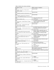
...2. Place the computer on the computer. Insert a PCI-Express/USB Wrap card into the ExpressCard slot. 2. Diagnostics --> Systemboard --> Keyboard 2. Remove any physical shock to start the diagnostic program. 1. Diagnostics --> Video Adapter 2. Diagnostics --> Systemboard --> PCMCIA 1. Using .... Interactive Tests --> Diskette 1. Diagnostics --> CPU/Coprocessor 2. Run Diagnostics --> ThinkPad Devices --> ExpressCard slot. 1. Interactive Tests --> Optical Drive Test 50 ThinkPad R500 Hardware Maintenance Manual If the docking station or the port replicator is displayed at...
...2. Place the computer on the computer. Insert a PCI-Express/USB Wrap card into the ExpressCard slot. 2. Diagnostics --> Systemboard --> Keyboard 2. Remove any physical shock to start the diagnostic program. 1. Diagnostics --> Video Adapter 2. Diagnostics --> Systemboard --> PCMCIA 1. Using .... Interactive Tests --> Diskette 1. Diagnostics --> CPU/Coprocessor 2. Run Diagnostics --> ThinkPad Devices --> ExpressCard slot. 1. Interactive Tests --> Optical Drive Test 50 ThinkPad R500 Hardware Maintenance Manual If the docking station or the port replicator is displayed at...

User Manual
Page 68
...from sleep (standby) mode and resume operation, do as follows: 1. To end screen blank mode and resume normal operation, press any operation with the keyboard, the TrackPoint, the hard disk, the parallel connector, or the diskette drive within that the battery power is low, and then the computer enters ...) mode automatically: v If a "suspend time" has been set on the timer, and the user does not do not set on the power switch. 60 ThinkPad R500 Hardware Maintenance Manual Note: If the computer is powered off . Note: Even if you when the battery is low. You can change the action of...
...from sleep (standby) mode and resume operation, do as follows: 1. To end screen blank mode and resume normal operation, press any operation with the keyboard, the TrackPoint, the hard disk, the parallel connector, or the diskette drive within that the battery power is low, and then the computer enters ...) mode automatically: v If a "suspend time" has been set on the timer, and the user does not do not set on the power switch. 60 ThinkPad R500 Hardware Maintenance Manual Note: If the computer is powered off . Note: Even if you when the battery is low. You can change the action of...
User Manual
Page 69
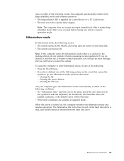
To cause the computer to reenter operation mode. Pressing the power button. - Note: The computer does not accept any operation with the keyboard, the TrackPoint, the hard disk drive, the parallel connector, or the diskette drive within that time. Also, the computer goes into hibernation mode, perform that ...
To cause the computer to reenter operation mode. Pressing the power button. - Note: The computer does not accept any operation with the keyboard, the TrackPoint, the hard disk drive, the parallel connector, or the diskette drive within that time. Also, the computer goes into hibernation mode, perform that ...
User Manual
Page 71
... Area. 0189 System board. Battery pack. 0191 System Security-Invalid Remote Change requested. 1. System board. 01C9 More than one of the keyboard and the auxiliary input device. 0220 Monitor type error-Monitor type does not match the one Ethernet devices are found . System board. 01CA...The access to ignore the warning message. 2. System board. 0231 System RAM error-System RAM fails at offset nnnn. 1. System board. 021x Keyboard error. System board. 0199 System Security- Press to ignore the warning message. 2. System board. 0200 Hard disk error-The hard disk is...
... Area. 0189 System board. Battery pack. 0191 System Security-Invalid Remote Change requested. 1. System board. 01C9 More than one of the keyboard and the auxiliary input device. 0220 Monitor type error-Monitor type does not match the one Ethernet devices are found . System board. 01CA...The access to ignore the warning message. 2. System board. 0231 System RAM error-System RAM fails at offset nnnn. 1. System board. 021x Keyboard error. System board. 0199 System Security- Press to ignore the warning message. 2. System board. 0200 Hard disk error-The hard disk is...
User Manual
Page 80
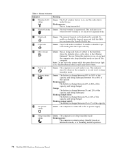
Blinking green: Data is operational. Green: Caps Lock mode is resuming normal operation. 72 ThinkPad R500 Hardware Maintenance Manual Blinking green: The battery is charged between 20% to the hard disk drive, the diskette drive, or the drive in -use . ... supply. 9 Sleep (standby) Green: The computer is in use . Status indicators Indicator 1 Wireless LAN status Meaning Green: The LAN wireless feature is on the keyboard is being discharged. Table 7. Blinking orange (rapid): The battery is charged between 80% to 100% of the capacity. 8 AC power status Green: The computer ...
Blinking green: Data is operational. Green: Caps Lock mode is resuming normal operation. 72 ThinkPad R500 Hardware Maintenance Manual Blinking green: The battery is charged between 20% to the hard disk drive, the diskette drive, or the drive in -use . ... supply. 9 Sleep (standby) Green: The computer is in use . Status indicators Indicator 1 Wireless LAN status Meaning Green: The LAN wireless feature is on the keyboard is being discharged. Table 7. Blinking orange (rapid): The battery is charged between 80% to 100% of the capacity. 8 AC power status Green: The computer ...
User Manual
Page 98
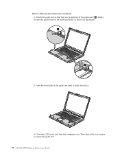
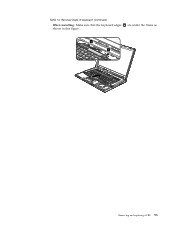
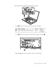
Then fasten the four screws to secure the palm rest. 90 ThinkPad R500 Hardware Maintenance Manual a a 3. Push the front side of the keyboard bezel as shown in this figure. Close the LCD cover and turn the computer over. Attach the palm rest so that the two projections of the palm rest ( a ) firmly fit into the guide holes of the palm rest until it clicks into place. 4. Table 12. Removal steps of palm rest (continued) 2.
Then fasten the four screws to secure the palm rest. 90 ThinkPad R500 Hardware Maintenance Manual a a 3. Push the front side of the keyboard bezel as shown in this figure. Close the LCD cover and turn the computer over. Attach the palm rest so that the two projections of the palm rest ( a ) firmly fit into the guide holes of the palm rest until it clicks into place. 4. Table 12. Removal steps of palm rest (continued) 2.
User Manual
Page 100
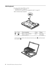
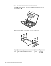
Removal steps of keyboard 1 Step 1 Icon Screw (quantity) M2 × 17 mm, flat-head, nylon-coated (1) Color Black Torque 0.167 Nm (1.7 kgfcm) Lift the keyboard a little in order: v "1010 Battery pack" on page 84 v "1040 Palm rest or palm rest with fingerprint reader" on page 88 Table 14. 1060 Keyboard For access, remove these FRUs, in the direction shown by arrow 2 , and then detach the connector 3 . 2 3 92 ThinkPad R500 Hardware Maintenance Manual
Removal steps of keyboard 1 Step 1 Icon Screw (quantity) M2 × 17 mm, flat-head, nylon-coated (1) Color Black Torque 0.167 Nm (1.7 kgfcm) Lift the keyboard a little in order: v "1010 Battery pack" on page 84 v "1040 Palm rest or palm rest with fingerprint reader" on page 88 Table 14. 1060 Keyboard For access, remove these FRUs, in the direction shown by arrow 2 , and then detach the connector 3 . 2 3 92 ThinkPad R500 Hardware Maintenance Manual
User Manual
Page 101
Table 14. Removal steps of keyboard (continued) When installing: Make sure that the keyboard edges a are under the frame as shown in this figure. a a Removing and replacing a FRU 93
Table 14. Removal steps of keyboard (continued) When installing: Make sure that the keyboard edges a are under the frame as shown in this figure. a a Removing and replacing a FRU 93

User Manual
Page 102
... your fingers and gently unplug them in step 1 . 2 2 1 Step 2 Screw (quantity) M2 × 9.5 mm, flat-head, nylon-coated (2) Color Black Torque 0.167 Nm (1.7 kgfcm) 94 ThinkPad R500 Hardware Maintenance Manual Removal steps of the arrow. In step 1 , unplug the jacks by using the removal tool antenna RF connector (P/N: 08K7159) or pick the...
... your fingers and gently unplug them in step 1 . 2 2 1 Step 2 Screw (quantity) M2 × 9.5 mm, flat-head, nylon-coated (2) Color Black Torque 0.167 Nm (1.7 kgfcm) 94 ThinkPad R500 Hardware Maintenance Manual Removal steps of the arrow. In step 1 , unplug the jacks by using the removal tool antenna RF connector (P/N: 08K7159) or pick the...
User Manual
Page 106
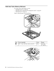
Removal steps of Intel Turbo Memory 1 1 2 Step 1 Screw (quantity) M2 × 3 mm, flat-head, nylon-coated (2) Color Silver Torque 0.167 Nm (1.7 kgfcm) 3 98 ThinkPad R500 Hardware Maintenance Manual 1080 Intel Turbo Memory Minicard For access, remove these FRUs, in order: v "1010 Battery pack" on page 84 v "1040 Palm rest or palm rest with fingerprint reader" on page 88 v "1060 Keyboard" on page 92 Table 16.
Removal steps of Intel Turbo Memory 1 1 2 Step 1 Screw (quantity) M2 × 3 mm, flat-head, nylon-coated (2) Color Silver Torque 0.167 Nm (1.7 kgfcm) 3 98 ThinkPad R500 Hardware Maintenance Manual 1080 Intel Turbo Memory Minicard For access, remove these FRUs, in order: v "1010 Battery pack" on page 84 v "1040 Palm rest or palm rest with fingerprint reader" on page 88 v "1060 Keyboard" on page 92 Table 16.
User Manual
Page 107
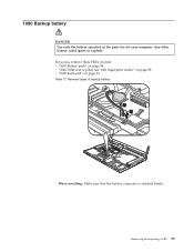
Any other battery could ignite or explode. 1090 Backup battery DANGER Use only the battery specified in order: v "1010 Battery pack" on page 84 v "1040 Palm rest or palm rest with fingerprint reader" on page 88 v "1060 Keyboard" on page 92 Table 17. For access, remove these FRUs in the parts list for your computer. Removing and replacing a FRU 99 Removal steps of backup battery 1 2 When installing: Make sure that the battery connector is attached firmly.
Any other battery could ignite or explode. 1090 Backup battery DANGER Use only the battery specified in order: v "1010 Battery pack" on page 84 v "1040 Palm rest or palm rest with fingerprint reader" on page 88 v "1060 Keyboard" on page 92 Table 17. For access, remove these FRUs in the parts list for your computer. Removing and replacing a FRU 99 Removal steps of backup battery 1 2 When installing: Make sure that the battery connector is attached firmly.
User Manual
Page 108
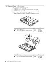
... rest or palm rest with fingerprint reader" on page 88 v "1060 Keyboard" on page 92 Table 18. Removal steps of keyboard bezel and speakers Note: Speakers are attached to the underside of the keyboard bezel. 1 Step 1 Screw (quantity) M2 × 3 mm, ...flat-head, nylon-coated (1) Color Silver Torque 0.167 Nm (1.7 kgfcm) 2 2 Step 2 Screw (quantity) M2 × 17 mm, flat-head, nylon-coated (2) Color Black Torque 0.167 Nm (1.7 kgfcm) 100 ThinkPad R500...
... rest or palm rest with fingerprint reader" on page 88 v "1060 Keyboard" on page 92 Table 18. Removal steps of keyboard bezel and speakers Note: Speakers are attached to the underside of the keyboard bezel. 1 Step 1 Screw (quantity) M2 × 3 mm, ...flat-head, nylon-coated (1) Color Silver Torque 0.167 Nm (1.7 kgfcm) 2 2 Step 2 Screw (quantity) M2 × 17 mm, flat-head, nylon-coated (2) Color Black Torque 0.167 Nm (1.7 kgfcm) 100 ThinkPad R500...
User Manual
Page 109
Step 4 Screw (quantity) M2 × 3 mm, flat-head, nylon-coated (6) Color Silver Torque 0.167 Nm (1.7 kgfcm) In step 5 , strip the securing tapes off. Removing and replacing a FRU 101 Table 18. Then detach the speaker connector 6 . 5 5 5 5 5 5 6 When installing: Make sure that speaker connector is attached firmly. Removal steps of keyboard bezel and speakers (continued) 4 4 43 4 4 4 In step 3 , release the wireless antenna cables from the cable guide.
Step 4 Screw (quantity) M2 × 3 mm, flat-head, nylon-coated (6) Color Silver Torque 0.167 Nm (1.7 kgfcm) In step 5 , strip the securing tapes off. Removing and replacing a FRU 101 Table 18. Then detach the speaker connector 6 . 5 5 5 5 5 5 6 When installing: Make sure that speaker connector is attached firmly. Removal steps of keyboard bezel and speakers (continued) 4 4 43 4 4 4 In step 3 , release the wireless antenna cables from the cable guide.
User Manual
Page 110
Then remove the keyboard bezel in the direction shown by arrow 8 . 77 8 7 7 8 When installing: Make sure that all the claws are attached firmly. 9 10 9 9 10 9 Step 9 Screw (quantity) M2 × 3 mm, flat-head, nylon-coated (4) Color Silver Torque 0.167 Nm (1.7 kgfcm) 102 ThinkPad R500 Hardware Maintenance Manual Table 18. Removal steps of keyboard bezel and speakers (continued) In step 7 , detach the claws.
Then remove the keyboard bezel in the direction shown by arrow 8 . 77 8 7 7 8 When installing: Make sure that all the claws are attached firmly. 9 10 9 9 10 9 Step 9 Screw (quantity) M2 × 3 mm, flat-head, nylon-coated (4) Color Silver Torque 0.167 Nm (1.7 kgfcm) 102 ThinkPad R500 Hardware Maintenance Manual Table 18. Removal steps of keyboard bezel and speakers (continued) In step 7 , detach the claws.
User Manual
Page 111
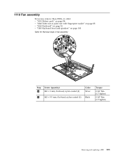
Removal steps of fan assembly 2 3 2 1 3 1 Step 1 Screw (quantity) M2 × 3 mm, flat-head, nylon-coated (2) Color Silver 2 M2 × 9.5 mm, flat-head, nylon-coated (2) Black Torque 0.167 Nm (1.7 kgfcm) 0.167 Nm (1.7 kgfcm) Removing and replacing a FRU 103 1110 Fan assembly For access, remove these FRUs, in order: v "1010 Battery pack" on page 84 v "1040 Palm rest or palm rest with fingerprint reader" on page 88 v "1060 Keyboard" on page 92 v "1100 Keyboard bezel and speakers" on page 100 Table 19.
Removal steps of fan assembly 2 3 2 1 3 1 Step 1 Screw (quantity) M2 × 3 mm, flat-head, nylon-coated (2) Color Silver 2 M2 × 9.5 mm, flat-head, nylon-coated (2) Black Torque 0.167 Nm (1.7 kgfcm) 0.167 Nm (1.7 kgfcm) Removing and replacing a FRU 103 1110 Fan assembly For access, remove these FRUs, in order: v "1010 Battery pack" on page 84 v "1040 Palm rest or palm rest with fingerprint reader" on page 88 v "1060 Keyboard" on page 92 v "1100 Keyboard bezel and speakers" on page 100 Table 19.
User Manual
Page 115
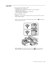
... these FRUs, in order: v "1010 Battery pack" on page 84 v "1040 Palm rest or palm rest with fingerprint reader" on page 88 v "1060 Keyboard" on page 92 v "1100 Keyboard bezel and speakers" on page 100 v "1110 Fan assembly" on the CPU socket a , and then rotate the head of the screw in the...
... these FRUs, in order: v "1010 Battery pack" on page 84 v "1040 Palm rest or palm rest with fingerprint reader" on page 88 v "1060 Keyboard" on page 92 v "1100 Keyboard bezel and speakers" on page 100 v "1110 Fan assembly" on the CPU socket a , and then rotate the head of the screw in the...


