Hardware Maintenance Manual
Page 4
... 149 Trademarks 150 ii Hardware Maintenance Manual Locations 101 Front view 101 Rear view 102 Bottom view 103 Chapter 10. 1170 System board assembly 85 1180 USB connector board and USB cable assembly 88 1190 DC-in cable and base cover 90 2010 LCD front bezel 94 2020 Speaker assembly 95 2030 Integrated camera...
... 149 Trademarks 150 ii Hardware Maintenance Manual Locations 101 Front view 101 Rear view 102 Bottom view 103 Chapter 10. 1170 System board assembly 85 1180 USB connector board and USB cable assembly 88 1190 DC-in cable and base cover 90 2010 LCD front bezel 94 2020 Speaker assembly 95 2030 Integrated camera...
Hardware Maintenance Manual
Page 94
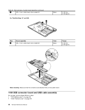
Table 28. Removal steps of system board assembly (continued) 1 M2 × 5 mm, wafer-head, nylon-coated (4) For ThinkPad Edge 14" and E40: 1 1 Black 0.181 Nm (1.85 kgfcm) Step 1 Screw (quantity) M2 × 5 mm, wafer-head, nylon-coated (2) Color Black Torque 0.181 Nm (1.85 kgfcm) 2 3 When installing: Make sure that the connectors are attached firmly to the system board. 1180 USB connector board and USB cable assembly For access, remove these FRUs in order: • "1010 Battery pack" on page 58 • "1030 Thermal cover" on page 59 88 Hardware Maintenance Manual
Table 28. Removal steps of system board assembly (continued) 1 M2 × 5 mm, wafer-head, nylon-coated (4) For ThinkPad Edge 14" and E40: 1 1 Black 0.181 Nm (1.85 kgfcm) Step 1 Screw (quantity) M2 × 5 mm, wafer-head, nylon-coated (2) Color Black Torque 0.181 Nm (1.85 kgfcm) 2 3 When installing: Make sure that the connectors are attached firmly to the system board. 1180 USB connector board and USB cable assembly For access, remove these FRUs in order: • "1010 Battery pack" on page 58 • "1030 Thermal cover" on page 59 88 Hardware Maintenance Manual
Hardware Maintenance Manual
Page 95
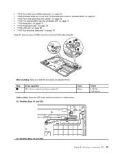
..." and E50: Torque 0.181 Nm (1.85 kgfcm) For ThinkPad Edge 14" and E40: Chapter 8. Removal steps of USB connector board and USB cable assembly 2 4 1 3 When installing: Make sure that the connectors are attached firmly. Removing or replacing a FRU 89 • "1040 Hard disk drive (HDD) assembly" on ...; "1160 Top shielding assembly" on page 83 Table 29. Step 2 Screw (quantity) M2 × 3 mm, wafer-head, nylon-coated (1) Color Black Cable routing: Route the USB cable assembly as shown in these figures.
..." and E50: Torque 0.181 Nm (1.85 kgfcm) For ThinkPad Edge 14" and E40: Chapter 8. Removal steps of USB connector board and USB cable assembly 2 4 1 3 When installing: Make sure that the connectors are attached firmly. Removing or replacing a FRU 89 • "1040 Hard disk drive (HDD) assembly" on ...; "1160 Top shielding assembly" on page 83 Table 29. Step 2 Screw (quantity) M2 × 3 mm, wafer-head, nylon-coated (1) Color Black Cable routing: Route the USB cable assembly as shown in these figures.
Hardware Maintenance Manual
Page 96
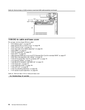
Table 29. Removal steps of USB connector board and USB cable assembly (continued) 1190 DC-in cable and base cover For access, remove these FRUs in cable and base cover For ThinkPad Edge 15" and E50: 90 Hardware Maintenance Manual Removal steps of DC-in order: • "1010 Battery pack" on page 58 • "1020 Optical... • "1140 Keyboard bezel" on page 78 • "1150 LCD unit" on page 80 • "1160 Top shielding assembly" on page 83 • "1170 System board assembly" on page 85 Table 30.
Table 29. Removal steps of USB connector board and USB cable assembly (continued) 1190 DC-in cable and base cover For access, remove these FRUs in cable and base cover For ThinkPad Edge 15" and E50: 90 Hardware Maintenance Manual Removal steps of DC-in order: • "1010 Battery pack" on page 58 • "1020 Optical... • "1140 Keyboard bezel" on page 78 • "1150 LCD unit" on page 80 • "1160 Top shielding assembly" on page 83 • "1170 System board assembly" on page 85 Table 30.


