Hardware Maintenance Manual
Page 3
... . . . 31 Lenovo Solution Center 31 FRU tests 34 Power system checkout 35 Checking the ac adapter 35 Checking operational charging 35 Checking the battery pack 36 Checking the backup battery 36 Chapter 4. Removing or replacing a FRU 57 1010 Battery pack 58 1020 Optical drive...Related service information 39 Restoring the factory contents by using PC-Doctor for DOS. . . . 28 Lenovo ThinkVantage Toolbox (Lenovo System Toolbox 31 PC-Doctor for replacing a system board 24 How to electrostatic discharge 3 Grounding requirements 4 Safety notices (multilingual translations 4 Laser ...
... . . . 31 Lenovo Solution Center 31 FRU tests 34 Power system checkout 35 Checking the ac adapter 35 Checking operational charging 35 Checking the battery pack 36 Checking the backup battery 36 Chapter 4. Removing or replacing a FRU 57 1010 Battery pack 58 1020 Optical drive...Related service information 39 Restoring the factory contents by using PC-Doctor for DOS. . . . 28 Lenovo ThinkVantage Toolbox (Lenovo System Toolbox 31 PC-Doctor for replacing a system board 24 How to electrostatic discharge 3 Grounding requirements 4 Safety notices (multilingual translations 4 Laser ...
Hardware Maintenance Manual
Page 41
... checkout To verify a symptom, do the following : 1. Reinstall the battery pack. Connect the ac adapter. 4. Chapter 3. Turn off the computer. 6. If the voltage is not correct, replace the ac adapter. 4. If the battery status indicator or icon does not turn on page 34. If the ..."Checking operational charging" on page 35 • "Checking the battery pack" on page 36 • "Checking the backup battery" on the computer. 5. Turn off the computer. 2. Measure the output voltage at the plug of the following : • Replace the system board. • If the problem persists, go...
... checkout To verify a symptom, do the following : 1. Reinstall the battery pack. Connect the ac adapter. 4. Chapter 3. Turn off the computer. 6. If the voltage is not correct, replace the ac adapter. 4. If the battery status indicator or icon does not turn on page 34. If the ..."Checking operational charging" on page 35 • "Checking the battery pack" on page 36 • "Checking the backup battery" on the computer. 5. Turn off the computer. 2. Measure the output voltage at the plug of the following : • Replace the system board. • If the problem persists, go...
Hardware Maintenance Manual
Page 42
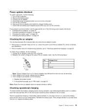
...following figure: Terminal 1 7 Voltage (V dc) + 0 to the Power Manager Battery Gauge icon in the icon tray of the backup battery. If the voltage is correct, replace the system board. This protects the battery pack from being overcharged or from it may not be 4 to 100% of... power remains; To get detailed information about the battery, double-click the Power Manager Battery Gauge icon. Checking the backup battery Do the following figure. 36 Hardware Maintenance Manual If the voltage is not correct, replace the battery pack. Turn the computer upside down , reinstall and...
...following figure: Terminal 1 7 Voltage (V dc) + 0 to the Power Manager Battery Gauge icon in the icon tray of the backup battery. If the voltage is correct, replace the system board. This protects the battery pack from being overcharged or from it may not be 4 to 100% of... power remains; To get detailed information about the battery, double-click the Power Manager Battery Gauge icon. Checking the backup battery Do the following figure. 36 Hardware Maintenance Manual If the voltage is not correct, replace the battery pack. Turn the computer upside down , reinstall and...

Hardware Maintenance Manual
Page 43
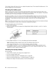
Wire Red Black Voltage (V dc) +2.5 to +3.2 Ground • If the voltage is correct, replace the system board. • If the voltage is not correct, replace the backup battery. • If the backup battery discharges quickly after replacement, replace the system board. Chapter 3. General checkout 37
Wire Red Black Voltage (V dc) +2.5 to +3.2 Ground • If the voltage is correct, replace the system board. • If the voltage is not correct, replace the backup battery. • If the backup battery discharges quickly after replacement, replace the system board. Chapter 3. General checkout 37
Hardware Maintenance Manual
Page 47
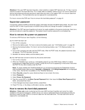
... from the hard disk drive. Select Password. 5. The hard disk drive can be made available to the service technician, neither Lenovo nor Lenovo authorized service technicians provide any services to reset either the user or the master HDP, or to the BIOS Setup Utility and... and cannot be replaced for a scheduled fee. Turn on the ThinkPad Notebook. 3. After the POST ends, the password prompt does not appear. Remove the backup battery. then enter the POP. The hard disk drive can be replaced for access to remove the battery pack, see "1110 Backup battery" on the computer...
... from the hard disk drive. Select Password. 5. The hard disk drive can be made available to the service technician, neither Lenovo nor Lenovo authorized service technicians provide any services to reset either the user or the master HDP, or to the BIOS Setup Utility and... and cannot be replaced for a scheduled fee. Turn on the ThinkPad Notebook. 3. After the POST ends, the password prompt does not appear. Remove the backup battery. then enter the POP. The hard disk drive can be replaced for access to remove the battery pack, see "1110 Backup battery" on the computer...
Hardware Maintenance Manual
Page 49
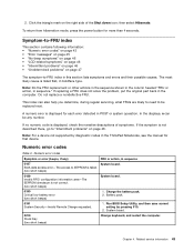
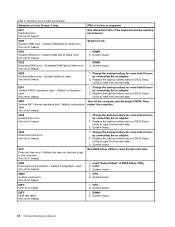
...access error-The access to -FRU index in POST or system operation. Battery pack. 0191 System Security-Invalid Remote Change requested. 1. Run BIOS Setup Utility, and then save current setting by diagnostic codes in the ThinkPad Notebooks, see the manual for each error detected in this section lists...press the power button for more than 4 seconds. Note: Do the FRU replacement or other actions in the sequence shown in the column headed "FRU or action, in the computer. This index can be replaced next. Charge the battery pack. 2. System board. 0210 Stuck Key (two short beeps) Change ...
...access error-The access to -FRU index in POST or system operation. Battery pack. 0191 System Security-Invalid Remote Change requested. 1. Run BIOS Setup Utility, and then save current setting by diagnostic codes in the ThinkPad Notebooks, see the manual for each error detected in this section lists...press the power button for more than 4 seconds. Note: Do the FRU replacement or other actions in the sequence shown in the column headed "FRU or action, in the computer. This index can be replaced next. Charge the battery pack. 2. System board. 0210 Stuck Key (two short beeps) Change ...
Hardware Maintenance Manual
Page 50
... short beeps) 1. System board. 02D0 System cache error. (two short beeps) 1. Default configuration used . (two short beeps) 1. Replace the backup battery and run BIOS Setup Utility to reset the time and date. 3. System board. 0270 Real-time clock error. (two short beeps) ...0260 System timer error. (two short beeps) 1. DIMM. 3. CPU. 2. DIMM. 2. Default configuration used. (two short beeps) 1. Replace the backup battery and run BIOS Setup Utility to reset the time and date. 0280 Previous boot incomplete- Extended RAM fails at offset nnnn. (two short ...
... short beeps) 1. System board. 02D0 System cache error. (two short beeps) 1. Default configuration used . (two short beeps) 1. Replace the backup battery and run BIOS Setup Utility to reset the time and date. 3. System board. 0270 Real-time clock error. (two short beeps) ...0260 System timer error. (two short beeps) 1. DIMM. 3. CPU. 2. DIMM. 2. Default configuration used. (two short beeps) 1. Replace the backup battery and run BIOS Setup Utility to reset the time and date. 0280 Previous boot incomplete- Extended RAM fails at offset nnnn. (two short ...
Hardware Maintenance Manual
Page 53
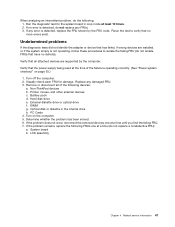
...FRUs that the power supply being used at a time until you find the failing FRU. 7. When analyzing an intermittent problem, do not replace any FRUs. 3. Remove or disconnect all attached devices are installed, or if the system simply is not operating, follow these procedures to ... all of the failure is detected, do the following devices: a. PC Cards 4. If no more errors exist. Non-ThinkPad devices b. Determine whether the problem has been solved. 6. Battery pack d. Optical disk or diskette in loop mode at least 10 times. 2. DIMM g. Related service information 47 Turn...
...FRUs that the power supply being used at a time until you find the failing FRU. 7. When analyzing an intermittent problem, do not replace any FRUs. 3. Remove or disconnect all attached devices are installed, or if the system simply is not operating, follow these procedures to ... all of the failure is detected, do the following devices: a. PC Cards 4. If no more errors exist. Non-ThinkPad devices b. Determine whether the problem has been solved. 6. Battery pack d. Optical disk or diskette in loop mode at least 10 times. 2. DIMM g. Related service information 47 Turn...
Hardware Maintenance Manual
Page 63
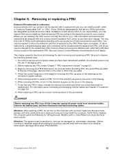
...30) days of your product or at http://www.lenovo.com/CRUs. Be sure to replace a FRU, turn off the computer, unplug all screws, springs, and other small parts are in place and none are available from electrical outlets, remove the battery pack, and then disconnect any computer unless you have...; You may be removed before the failing FRU. Any such FRUs are installing the CRU, Lenovo will be required to return the defective part that pertain to customers: Some problems with the replacement CRU; Verify this by the arrow in which they are designated as given by shaking the...
...30) days of your product or at http://www.lenovo.com/CRUs. Be sure to replace a FRU, turn off the computer, unplug all screws, springs, and other small parts are in place and none are available from electrical outlets, remove the battery pack, and then disconnect any computer unless you have...; You may be removed before the failing FRU. Any such FRUs are installing the CRU, Lenovo will be required to return the defective part that pertain to customers: Some problems with the replacement CRU; Verify this by the arrow in which they are designated as given by shaking the...

Hardware Maintenance Manual
Page 64
... should not be replaced unless this FRU: • "1010 Battery pack" on page 58 58 Hardware Maintenance Manual Holding the battery lock lever in the unlocked position 2 , remove the battery pack in the parts list for replacing a battery pack: Lenovo ThinkVantage Toolbox has an automatic battery diagnostic that determines if the battery pack is defective. 1010 Battery pack Important notice...
... should not be replaced unless this FRU: • "1010 Battery pack" on page 58 58 Hardware Maintenance Manual Holding the battery lock lever in the unlocked position 2 , remove the battery pack in the parts list for replacing a battery pack: Lenovo ThinkVantage Toolbox has an automatic battery diagnostic that determines if the battery pack is defective. 1010 Battery pack Important notice...

Hardware Maintenance Manual
Page 65
Table 9. Removing or replacing a FRU 59 Removal steps of optical drive or travel cover 1 Step 1 Screw (quantity) M2 × 8 mm, wafer-head, nylon-coated (1) 2 3 Color Black Torque 0.181 Nm (1.85 kgfcm) 1030 Thermal cover For access, remove this FRU: • "1010 Battery pack" on page 58 Chapter 8.
Table 9. Removing or replacing a FRU 59 Removal steps of optical drive or travel cover 1 Step 1 Screw (quantity) M2 × 8 mm, wafer-head, nylon-coated (1) 2 3 Color Black Torque 0.181 Nm (1.85 kgfcm) 1030 Thermal cover For access, remove this FRU: • "1010 Battery pack" on page 58 Chapter 8.

Hardware Maintenance Manual
Page 67
To do so, you might bend or break it. 1050 DIMM For access, remove these FRUs in order: • "1010 Battery pack" on page 58 • "1030 Thermal cover" on page 59 Chapter 8. Removing or replacing a FRU 61 Table 11. Removal steps of HDD assembly 1 When installing: Make sure that the HDD connector is attached firmly. 2 a When installing: Do not apply excessive force to the HDD bracket a .
To do so, you might bend or break it. 1050 DIMM For access, remove these FRUs in order: • "1010 Battery pack" on page 58 • "1030 Thermal cover" on page 59 Chapter 8. Removing or replacing a FRU 61 Table 11. Removal steps of HDD assembly 1 When installing: Make sure that the HDD connector is attached firmly. 2 a When installing: Do not apply excessive force to the HDD bracket a .
Hardware Maintenance Manual
Page 69
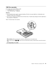
... to 2f in order, but do not remove them. For Thinkpad Edge 15" and E50: Chapter 8. Table 13. Note: Loosen the screws 2a to the fan motor. When you attach the fan, secure the screws in order: • "1010 Battery pack" on page 58 • "1030 Thermal cover" on... page 59 Attention: • Do not handle the fan roughly. 1060 Fan assembly For access, remove these FRUs in order. Improper handling of fan assembly 1 When installing: Make sure that the fan connector is attached firmly to mulfunction. Removing or replacing...
... to 2f in order, but do not remove them. For Thinkpad Edge 15" and E50: Chapter 8. Table 13. Note: Loosen the screws 2a to the fan motor. When you attach the fan, secure the screws in order: • "1010 Battery pack" on page 58 • "1030 Thermal cover" on... page 59 Attention: • Do not handle the fan roughly. 1060 Fan assembly For access, remove these FRUs in order. Improper handling of fan assembly 1 When installing: Make sure that the fan connector is attached firmly to mulfunction. Removing or replacing...

Hardware Maintenance Manual
Page 73
Removing or replacing a FRU 67 1080 Wireless WAN slot cover and PCI Express Mini Card for wireless WAN Note: Loosen the screw 1 , but do not remove it. 1 2 Chapter 8. Removal steps of wireless WAN slot cover and PCI Express Mini Card for wireless WAN For access, remove this FRU: • "1010 Battery pack" on page 58 Table 15.
Removing or replacing a FRU 67 1080 Wireless WAN slot cover and PCI Express Mini Card for wireless WAN Note: Loosen the screw 1 , but do not remove it. 1 2 Chapter 8. Removal steps of wireless WAN slot cover and PCI Express Mini Card for wireless WAN For access, remove this FRU: • "1010 Battery pack" on page 58 Table 15.

Hardware Maintenance Manual
Page 75
Removing or replacing a FRU 69 Removal steps of SIM card (continued) 1 3 2 1090 Palm rest assembly with cables For access, remove these FRUs in this section, which are the same for a palm rest with the fingerprint reader, the sensor is attached to the palm rest FRU. If the fingerprint reader has any defects, you can replace it by the procedures given in order: • "1010 Battery pack" on page 58 • "1020 Optical drive or travel cover" on page 58 Note: In models with or without a fingerprint reader. Table 16. Chapter 8.
Removing or replacing a FRU 69 Removal steps of SIM card (continued) 1 3 2 1090 Palm rest assembly with cables For access, remove these FRUs in this section, which are the same for a palm rest with the fingerprint reader, the sensor is attached to the palm rest FRU. If the fingerprint reader has any defects, you can replace it by the procedures given in order: • "1010 Battery pack" on page 58 • "1020 Optical drive or travel cover" on page 58 Note: In models with or without a fingerprint reader. Table 16. Chapter 8.

Hardware Maintenance Manual
Page 81
... card (BDC-2) For access, remove these FRUs in order: • "1010 Battery pack" on page 58 • "1020 Optical drive or travel cover" on page 58 • "1090 Palm rest assembly with cables" on page 69 Chapter 8. Removing or replacing a FRU 75 Removal steps of BDC-2 1 2 Step 1 Screw (quantity) M2...connector on bottom side of the card is attached firmly to the system board. 1130 Keyboard For access, remove these FRUs in order: • "1010 Battery pack" on page 58 • "1020 Optical drive or travel cover" on page 58 • "1090 Palm rest assembly with cables" on page...
... card (BDC-2) For access, remove these FRUs in order: • "1010 Battery pack" on page 58 • "1020 Optical drive or travel cover" on page 58 • "1090 Palm rest assembly with cables" on page 69 Chapter 8. Removing or replacing a FRU 75 Removal steps of BDC-2 1 2 Step 1 Screw (quantity) M2...connector on bottom side of the card is attached firmly to the system board. 1130 Keyboard For access, remove these FRUs in order: • "1010 Battery pack" on page 58 • "1020 Optical drive or travel cover" on page 58 • "1090 Palm rest assembly with cables" on page...
Hardware Maintenance Manual
Page 89
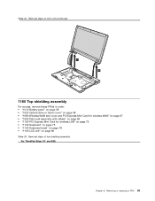
Removal steps of LCD unit (continued) 6 6 1160 Top shielding assembly For access, remove these FRUs in order: • "1010 Battery pack" on page 58 • "1020 Optical drive or travel cover" on page 58 • "1080 Wireless WAN slot cover and PCI Express Mini Card ... 72 • "1130 Keyboard" on page 75 • "1140 Keyboard bezel" on page 78 • "1150 LCD unit" on page 80 Table 26. Removing or replacing a FRU 83 Removal steps of top shielding assembly For ThinkPad Edge 15" and E50: Chapter 8. Table 25.
Removal steps of LCD unit (continued) 6 6 1160 Top shielding assembly For access, remove these FRUs in order: • "1010 Battery pack" on page 58 • "1020 Optical drive or travel cover" on page 58 • "1080 Wireless WAN slot cover and PCI Express Mini Card ... 72 • "1130 Keyboard" on page 75 • "1140 Keyboard bezel" on page 78 • "1150 LCD unit" on page 80 Table 26. Removing or replacing a FRU 83 Removal steps of top shielding assembly For ThinkPad Edge 15" and E50: Chapter 8. Table 25.

Hardware Maintenance Manual
Page 91
Place the computer on page 78 Chapter 8. Run Diagnostics ➙ ThinkPad Devices ➙ HDD Active Protection Test. For access, remove these FRUs, in order: • "1010 Battery pack" on page 58 • "1020 Optical drive or travel cover" on page 58 • "1030 Thermal cover" ... G-forces. The procedure is running. Attention: Do not apply physical shock to as much as an ESD mat or conductive corrugated material. Removing or replacing a FRU 85 Removal steps of as little as follows: 1. Note: Dropping a system board from a height of top shielding assembly (continued) 1...
Place the computer on page 78 Chapter 8. Run Diagnostics ➙ ThinkPad Devices ➙ HDD Active Protection Test. For access, remove these FRUs, in order: • "1010 Battery pack" on page 58 • "1020 Optical drive or travel cover" on page 58 • "1030 Thermal cover" ... G-forces. The procedure is running. Attention: Do not apply physical shock to as much as an ESD mat or conductive corrugated material. Removing or replacing a FRU 85 Removal steps of as little as follows: 1. Note: Dropping a system board from a height of top shielding assembly (continued) 1...
Hardware Maintenance Manual
Page 98
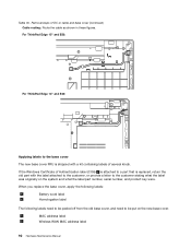
...Battery word label 6 Homologation label The following labels need to be peeled off from the old base cover, and need to a part that is replaced, return the old part with a kit containing labels of DC-in cable and base cover (continued) Cable routing: Route the cable as shown in these figures. For ThinkPad Edge... 15" and E50: For ThinkPad Edge 14" and E40: Applying labels to the ...
...Battery word label 6 Homologation label The following labels need to be peeled off from the old base cover, and need to a part that is replaced, return the old part with a kit containing labels of DC-in cable and base cover (continued) Cable routing: Route the cable as shown in these figures. For ThinkPad Edge... 15" and E50: For ThinkPad Edge 14" and E40: Applying labels to the ...

Hardware Maintenance Manual
Page 101
... all the latches are attached firmly. Then secure the bezel with the screws. 2020 Speaker assembly For access, remove these FRUs in order: • "1010 Battery pack" on page 58 • "1080 Wireless WAN slot cover and PCI Express Mini Card for wireless WAN" on page 67 • "1090 Palm rest... • "1150 LCD unit" on page 80 • "2010 LCD front bezel" on page 94 Table 32. Removal steps of speaker assembly 1 3 1 2 Chapter 8. Removing or replacing a FRU 95
... all the latches are attached firmly. Then secure the bezel with the screws. 2020 Speaker assembly For access, remove these FRUs in order: • "1010 Battery pack" on page 58 • "1080 Wireless WAN slot cover and PCI Express Mini Card for wireless WAN" on page 67 • "1090 Palm rest... • "1150 LCD unit" on page 80 • "2010 LCD front bezel" on page 94 Table 32. Removal steps of speaker assembly 1 3 1 2 Chapter 8. Removing or replacing a FRU 95


