
User Manual
Page 1
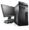
ThinkCentre User Guide Machine Types: 4163, 5042, 5046, 5052, 5054, 5056, 5058, 5060, 5062, 5064, and 5066
ThinkCentre User Guide Machine Types: 4163, 5042, 5046, 5052, 5054, 5056, 5058, 5060, 5062, 5064, and 5066

User Manual
Page 3
ThinkCentre User Guide Machine Types: 4163, 5042, 5046, 5052, 5054, 5056, 5058, 5060, 5062, 5064, and 5066
ThinkCentre User Guide Machine Types: 4163, 5042, 5046, 5052, 5054, 5056, 5058, 5060, 5062, 5064, and 5066
Hardware Maintenance Manual
Page 1
ThinkCentre Hardware Maintenance Manual Machine Types: 4162, 4163, 5041, 5042, 5044, 5046, 5051, 5052, 5053, 5054, 5055, 5056, 5057, 5058, 5059, 5060, 5061, 5062, 5063, 5064, 5065, and 5066
ThinkCentre Hardware Maintenance Manual Machine Types: 4162, 4163, 5041, 5042, 5044, 5046, 5051, 5052, 5053, 5054, 5055, 5056, 5057, 5058, 5059, 5060, 5061, 5062, 5063, 5064, 5065, and 5066
Hardware Maintenance Manual
Page 3
ThinkCentre Hardware Maintenance Manual Machine Types: 4162, 4163, 5041, 5042, 5044, 5046, 5051, 5052, 5053, 5054, 5055, 5056, 5057, 5058, 5059, 5060, 5061, 5062, 5063, 5064, 5065, and 5066
ThinkCentre Hardware Maintenance Manual Machine Types: 4162, 4163, 5041, 5042, 5044, 5046, 5051, 5052, 5053, 5054, 5055, 5056, 5057, 5058, 5059, 5060, 5061, 5062, 5063, 5064, 5065, and 5066
Hardware Maintenance Manual
Page 5
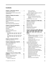
..., 5051, 5053, 5055, 5057, 5059, 5061, 5063, and 5065 34 For machine types: 4163, 5042, 5046, 5052, 5054, 5056, 5058, 5060, 5062, 5064, and 5066 35 Chapter 4. Diagnostic programs . . . 39 Lenovo ThinkVantage Toolbox 39 Lenovo Solution Center 39 PC-Doctor for DOS 40 Creating a diagnostic disc 40 Running the diagnostic program from the...
..., 5051, 5053, 5055, 5057, 5059, 5061, 5063, and 5065 34 For machine types: 4163, 5042, 5046, 5052, 5054, 5056, 5058, 5060, 5062, 5064, and 5066 35 Chapter 4. Diagnostic programs . . . 39 Lenovo ThinkVantage Toolbox 39 Lenovo Solution Center 39 PC-Doctor for DOS 40 Creating a diagnostic disc 40 Running the diagnostic program from the...
Hardware Maintenance Manual
Page 6
Notices 307 Television output notice 308 European conformance CE mark 308 Trademarks 308 Index 309 iv ThinkCentre Hardware Maintenance Manual Replacing FRUs (Machine Types: 4163, 5042, 5046, 5052, 5054, 5056, 5058, 5060, 5062, 5064, and 5066 101 Locations 101 Locating connectors, controls, and indicators on the... and Power Interface (ACPI) BIOS 305 Automatic Power-On features 305 Appendix A. FRU lists 135 Overall: MT 4163, 5042, 5046, 5054, 5056, 5058, 5062, and 5064 135 Mechanical FRUs 149 Keyboard and Mouse 154 Adapters and miscellaneous FRUs 186 Power Cords 190 Recovery ...
Notices 307 Television output notice 308 European conformance CE mark 308 Trademarks 308 Index 309 iv ThinkCentre Hardware Maintenance Manual Replacing FRUs (Machine Types: 4163, 5042, 5046, 5052, 5054, 5056, 5058, 5060, 5062, 5064, and 5066 101 Locations 101 Locating connectors, controls, and indicators on the... and Power Interface (ACPI) BIOS 305 Automatic Power-On features 305 Appendix A. FRU lists 135 Overall: MT 4163, 5042, 5046, 5054, 5056, 5058, 5062, and 5064 135 Mechanical FRUs 149 Keyboard and Mouse 154 Adapters and miscellaneous FRUs 186 Power Cords 190 Recovery ...
Hardware Maintenance Manual
Page 41
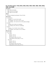
For machine types: 4163, 5042, 5046, 5052, 5054, 5056, 5058, 5060, 5062, 5064, and 5066. Dimensions Width: 99 mm (3.9 inches) Height: 335 mm (13.19 inches) Depth: 382 mm (15.04 inches) Weight ...
For machine types: 4163, 5042, 5046, 5052, 5054, 5056, 5058, 5060, 5062, 5064, and 5066. Dimensions Width: 99 mm (3.9 inches) Height: 335 mm (13.19 inches) Depth: 382 mm (15.04 inches) Weight ...
Hardware Maintenance Manual
Page 107
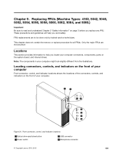
...computer. Front connector, control, and indicator locations 1 Optical drive eject/close button 2 Power switch 5 USB connector 6 Microphone connector © Copyright Lenovo 2010, 2012 101 Only the major FRUs are to read and understand Chapter 2 "Safety information" on the system board, and internal drives. This... chapter does not contain the remove or replace procedure for all FRUs. Replacing FRUs (Machine Types: 4163, 5042, 5046, 5052, 5054, 5056, 5058, 5060, 5062, 5064, and 5066.) Important Be sure to be done only by trained service technicians. FRU replacements are ...
...computer. Front connector, control, and indicator locations 1 Optical drive eject/close button 2 Power switch 5 USB connector 6 Microphone connector © Copyright Lenovo 2010, 2012 101 Only the major FRUs are to read and understand Chapter 2 "Safety information" on the system board, and internal drives. This... chapter does not contain the remove or replace procedure for all FRUs. Replacing FRUs (Machine Types: 4163, 5042, 5046, 5052, 5054, 5056, 5058, 5060, 5062, 5064, and 5066.) Important Be sure to be done only by trained service technicians. FRU replacements are ...
Hardware Maintenance Manual
Page 109
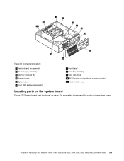
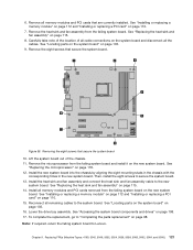
Figure 36. Replacing FRUs (Machine Types: 4163, 5042, 5046, 5052, 5054, 5056, 5058, 5060, 5062, 5064, and 5066.) 103 Component locations 1 Heat sink and fan assembly 2 Power supply assembly 3 Memory modules (2) 4 System board 5 Optical drive 6 Front USB and audio assembly 7 Front bezel 8 Front fan assembly 9 Hard disk drive 10 PCI Express card (available in some models) 11 Heat sink fan duct Locating parts on the system board Figure 37 "System board part locations" on page 104 shows the locations of the parts on the system board. Chapter 9.
Figure 36. Replacing FRUs (Machine Types: 4163, 5042, 5046, 5052, 5054, 5056, 5058, 5060, 5062, 5064, and 5066.) 103 Component locations 1 Heat sink and fan assembly 2 Power supply assembly 3 Memory modules (2) 4 System board 5 Optical drive 6 Front USB and audio assembly 7 Front bezel 8 Front fan assembly 9 Hard disk drive 10 PCI Express card (available in some models) 11 Heat sink fan duct Locating parts on the system board Figure 37 "System board part locations" on page 104 shows the locations of the parts on the system board. Chapter 9.

Hardware Maintenance Manual
Page 110
... correctly connect the cables to the appropriate section in Chapter 9 "Replacing FRUs (Machine Types: 4163, 5042, 5046, 5052, 5054, 5056, 5058, 5060, 5062, 5064, and 5066.)" on page 101 for your computer. 104 ThinkCentre Hardware Maintenance Manual Figure 37. Internal drives are devices that you can add drives to your computer to...
... correctly connect the cables to the appropriate section in Chapter 9 "Replacing FRUs (Machine Types: 4163, 5042, 5046, 5052, 5054, 5056, 5058, 5060, 5062, 5064, and 5066.)" on page 101 for your computer. 104 ThinkCentre Hardware Maintenance Manual Figure 37. Internal drives are devices that you can add drives to your computer to...
Hardware Maintenance Manual
Page 111
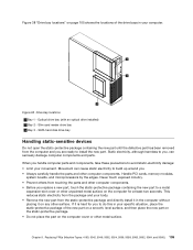
... the static-protective package of the drive bays in the computer without placing it in your movement. Replacing FRUs (Machine Types: 4163, 5042, 5046, 5052, 5054, 5056, 5058, 5060, 5062, 5064, and 5066.) 105 SATA hard disk drive bay Handling static-sensitive devices Do not open the static-protective package containing...
... the static-protective package of the drive bays in the computer without placing it in your movement. Replacing FRUs (Machine Types: 4163, 5042, 5046, 5052, 5054, 5056, 5058, 5060, 5062, 5064, and 5066.) 105 SATA hard disk drive bay Handling static-sensitive devices Do not open the static-protective package containing...

Hardware Maintenance Manual
Page 113
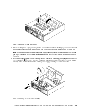
...disconnect all power cords from electrical outlets and disconnect all attached devices and the computer. Replacing FRUs (Machine Types: 4163, 5042, 5046, 5052, 5054, 5056, 5058, 5060, 5062, 5064, and 5066.) 107 Remove all media from the computer. Carefully lay the front bezel aside without disconnecting ...Remove the computer cover. Remove the front bezel by releasing the three plastic tabs on the top of the ThinkCentre Safety and Warranty Guide, go to: http://www.lenovo.com/support This section provides instructions on page 106. 3. Figure 39. Removing the computer cover Removing and ...
...disconnect all power cords from electrical outlets and disconnect all attached devices and the computer. Replacing FRUs (Machine Types: 4163, 5042, 5046, 5052, 5054, 5056, 5058, 5060, 5062, 5064, and 5066.) 107 Remove all media from the computer. Carefully lay the front bezel aside without disconnecting ...Remove the computer cover. Remove the front bezel by releasing the three plastic tabs on the top of the ThinkCentre Safety and Warranty Guide, go to: http://www.lenovo.com/support This section provides instructions on page 106. 3. Figure 39. Removing the computer cover Removing and ...
Hardware Maintenance Manual
Page 115
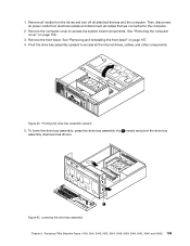
... and pivot the drive bay assembly downward as shown. See "Removing the computer cover" on page 107. 4. 1. Replacing FRUs (Machine Types: 4163, 5042, 5046, 5052, 5054, 5056, 5058, 5060, 5062, 5064, and 5066.) 109 Remove the front bezel. Pivoting the drive bay assembly upward 5.
... and pivot the drive bay assembly downward as shown. See "Removing the computer cover" on page 107. 4. 1. Replacing FRUs (Machine Types: 4163, 5042, 5046, 5052, 5054, 5056, 5058, 5060, 5062, 5064, and 5066.) 109 Remove the front bezel. Pivoting the drive bay assembly upward 5.
Hardware Maintenance Manual
Page 117
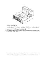
Chapter 9. Remove the new PCI card from its static-protective package. 5. Figure 44. Replacing FRUs (Machine Types: 4163, 5042, 5046, 5052, 5054, 5056, 5058, 5060, 5062, 5064, and 5066.) 111 See "Locating parts on the system board" on the system board. Then, install the screw to identify the types of PCI card slots. 4. Install the new PCI card into the appropriate PCI card slot on page 103 to secure the new PCI card in place. Removing the PCI card • If you are installing a PCI card, remove the appropriate PCI card slot cover.
Chapter 9. Remove the new PCI card from its static-protective package. 5. Figure 44. Replacing FRUs (Machine Types: 4163, 5042, 5046, 5052, 5054, 5056, 5058, 5060, 5062, 5064, and 5066.) 111 See "Locating parts on the system board" on the system board. Then, install the screw to identify the types of PCI card slots. 4. Install the new PCI card into the appropriate PCI card slot on page 103 to secure the new PCI card in place. Removing the PCI card • If you are installing a PCI card, remove the appropriate PCI card slot cover.

Hardware Maintenance Manual
Page 119
... and remove the old memory module that the notch 1 on the new memory module is currently installed. Replacing FRUs (Machine Types: 4163, 5042, 5046, 5052, 5054, 5056, 5058, 5060, 5062, 5064, and 5066.) 113 Position the new memory module over the memory slot. • If you want to install the memory...
... and remove the old memory module that the notch 1 on the new memory module is currently installed. Replacing FRUs (Machine Types: 4163, 5042, 5046, 5052, 5054, 5056, 5058, 5060, 5062, 5064, and 5066.) 113 Position the new memory module over the memory slot. • If you want to install the memory...

Hardware Maintenance Manual
Page 121
.... This is turned on page 106. CAUTION: The heat sink and fan assembly might be very hot. Replacing FRUs (Machine Types: 4163, 5042, 5046, 5052, 5054, 5056, 5058, 5060, 5062, 5064, and 5066.) 115 Figure 49. Figure 50. Lower the drive bay assembly. See "Completing the parts replacement" on page 43... the heat sink and fan assembly Attention: Do not open your computer. Remove the computer cover. Installing the new battery 8. To obtain a copy of the ThinkCentre Safety and Warranty Guide, go to: http://www.lenovo.com/support This section provides instructions on page 108. 10.
.... This is turned on page 106. CAUTION: The heat sink and fan assembly might be very hot. Replacing FRUs (Machine Types: 4163, 5042, 5046, 5052, 5054, 5056, 5058, 5060, 5062, 5064, and 5066.) 115 Figure 49. Figure 50. Lower the drive bay assembly. See "Completing the parts replacement" on page 43... the heat sink and fan assembly Attention: Do not open your computer. Remove the computer cover. Installing the new battery 8. To obtain a copy of the ThinkCentre Safety and Warranty Guide, go to: http://www.lenovo.com/support This section provides instructions on page 108. 10.

Hardware Maintenance Manual
Page 123
... secure the heat sink and fan assembly 7. Install the two screws to free it from the microprocessor. Replacing FRUs (Machine Types: 4163, 5042, 5046, 5052, 5054, 5056, 5058, 5060, 5062, 5064, and 5066.) 117 Make sure that you can easily connect the new heat sink and fan assembly cable to the...
... secure the heat sink and fan assembly 7. Install the two screws to free it from the microprocessor. Replacing FRUs (Machine Types: 4163, 5042, 5046, 5052, 5054, 5056, 5058, 5060, 5062, 5064, and 5066.) 117 Make sure that you can easily connect the new heat sink and fan assembly cable to the...
Hardware Maintenance Manual
Page 125
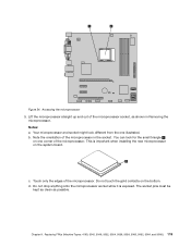
... of the microprocessor in Removing the microprocessor. Do not touch the gold contacts on one illustrated. d. Chapter 9. b. Replacing FRUs (Machine Types: 4163, 5042, 5046, 5052, 5054, 5056, 5058, 5060, 5062, 5064, and 5066.) 119 You can look different from the one corner of the microprocessor socket, as possible. Accessing the microprocessor...
... of the microprocessor in Removing the microprocessor. Do not touch the gold contacts on one illustrated. d. Chapter 9. b. Replacing FRUs (Machine Types: 4163, 5042, 5046, 5052, 5054, 5056, 5058, 5060, 5062, 5064, and 5066.) 119 You can look different from the one corner of the microprocessor socket, as possible. Accessing the microprocessor...
Hardware Maintenance Manual
Page 127
...or replacing a PCI card" on page 118. 12. Remove the eight screws that secure the system board. Replacing FRUs (Machine Types: 4163, 5042, 5046, 5052, 5054, 5056, 5058, 5060, 5062, 5064, and 5066.) 121 6. Figure 56. See "Replacing the microprocessor" on page 110. 7. Note: If required, return the ...board. Lower the drive bay assembly. See "Replacing the heat sink and fan assembly" on page 98. To complete the replacement, go to Lenovo. Carefully take note of the location of the chassis. 11. Install the new system board into the chassis by aligning the eight mounting studs in...
...or replacing a PCI card" on page 118. 12. Remove the eight screws that secure the system board. Replacing FRUs (Machine Types: 4163, 5042, 5046, 5052, 5054, 5056, 5058, 5060, 5062, 5064, and 5066.) 121 6. Figure 56. See "Replacing the microprocessor" on page 110. 7. Note: If required, return the ...board. Lower the drive bay assembly. See "Replacing the heat sink and fan assembly" on page 98. To complete the replacement, go to Lenovo. Carefully take note of the location of the chassis. 11. Install the new system board into the chassis by aligning the eight mounting studs in...
Hardware Maintenance Manual
Page 129
... secure the cables to the front of the computer. Removing the power supply assembly Chapter 9. Figure 58. Replacing FRUs (Machine Types: 4163, 5042, 5046, 5052, 5054, 5056, 5058, 5060, 5062, 5064, and 5066.) 123 Disconnect the power supply assembly cables from all drives and from some cable clips or ties that...
... secure the cables to the front of the computer. Removing the power supply assembly Chapter 9. Figure 58. Replacing FRUs (Machine Types: 4163, 5042, 5046, 5052, 5054, 5056, 5058, 5060, 5062, 5064, and 5066.) 123 Disconnect the power supply assembly cables from all drives and from some cable clips or ties that...