Hardware Maintenance Manual
Page 92
... before reading and understanding the "Important safety information" in the ThinkCentre Safety and Warranty Guide that came with your computer. See "Opening the computer cover" on page 89. Slide the new hard disk drive into the drive bay until it snaps into the bracket 8. Remove the front bezel ...the bezel forward to the optical drive. 11. To obtain a copy of the new hard disk drive. 9. To replace the optical drive: 1. Connect the signal and power cables to the rear of the ThinkCentre Safety and Warranty Guide, go to: http://www.lenovo.com/support This section provides instructions...
... before reading and understanding the "Important safety information" in the ThinkCentre Safety and Warranty Guide that came with your computer. See "Opening the computer cover" on page 89. Slide the new hard disk drive into the drive bay until it snaps into the bracket 8. Remove the front bezel ...the bezel forward to the optical drive. 11. To obtain a copy of the new hard disk drive. 9. To replace the optical drive: 1. Connect the signal and power cables to the rear of the ThinkCentre Safety and Warranty Guide, go to: http://www.lenovo.com/support This section provides instructions...

Hardware Maintenance Manual
Page 100
... button to : http://www.lenovo.com/support Note: Depending on...cover. Important When you receive a new hard disk drive, you to restore the contents of the ThinkCentre Safety and Warranty Guide, go to release the hard disk drive cage from the hard disk drive. 4. Go to replace the secondary hard disk drive...drive to "Recovering software" in the ThinkCentre Safety and Warranty Guide that do not have an internal hard disk drive and use a remote hard disk drive accessed through the SMC - For more information on page 73. 2. For computer models that came with a secondary hard disk drive bay...
... button to : http://www.lenovo.com/support Note: Depending on...cover. Important When you receive a new hard disk drive, you to restore the contents of the ThinkCentre Safety and Warranty Guide, go to release the hard disk drive cage from the hard disk drive. 4. Go to replace the secondary hard disk drive...drive to "Recovering software" in the ThinkCentre Safety and Warranty Guide that do not have an internal hard disk drive and use a remote hard disk drive accessed through the SMC - For more information on page 73. 2. For computer models that came with a secondary hard disk drive bay...
Hardware Maintenance Manual
Page 103
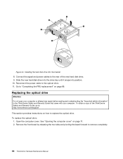
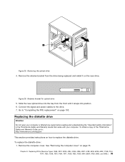
... the retainer bracket from the front until it on how to the drive. 7. Connect the signal and power cables to replace the diskette drive. To replace the diskette drive: 1. See "Removing the computer cover" on page 103. Chapter 8. Figure 26. Replacing FRUs (Machine Types: 3063, 3231, ..., and 9965.) 95 To obtain a copy of the ThinkCentre Safety and Warranty Guide, go to: http://www.lenovo.com/support This section provides instructions on the new drive. Slide the new optical drive into the bay from the drive being replaced and install it snaps into position. 6. Retainer...
... the retainer bracket from the front until it on how to the drive. 7. Connect the signal and power cables to replace the diskette drive. To replace the diskette drive: 1. See "Removing the computer cover" on page 103. Chapter 8. Figure 26. Replacing FRUs (Machine Types: 3063, 3231, ..., and 9965.) 95 To obtain a copy of the ThinkCentre Safety and Warranty Guide, go to: http://www.lenovo.com/support This section provides instructions on the new drive. Slide the new optical drive into the bay from the drive being replaced and install it snaps into position. 6. Retainer...

Hardware Maintenance Manual
Page 116
...drives: 1. See "Replacing the hard disk drive" on how to : http://www.lenovo.com/support This section provides instructions on page 122. To obtain a copy of any repair before closing the computer cover to prevent damage to access the internal components. Figure 40. See "Opening the computer cover...disconnect from the drives or the system board. Pivoting the drive bay assembly 108 ThinkCentre Hardware Maintenance Manual On some models, you might need to pivot the drive bay assembly upward and remove the hard disk drive to the hard disk drive. Open the computer cover. Note: Make...
...drives: 1. See "Replacing the hard disk drive" on how to : http://www.lenovo.com/support This section provides instructions on page 122. To obtain a copy of any repair before closing the computer cover to prevent damage to access the internal components. Figure 40. See "Opening the computer cover...disconnect from the drives or the system board. Pivoting the drive bay assembly 108 ThinkCentre Hardware Maintenance Manual On some models, you might need to pivot the drive bay assembly upward and remove the hard disk drive to the hard disk drive. Open the computer cover. Note: Make...
Hardware Maintenance Manual
Page 120
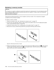
... 112 ThinkCentre Hardware Maintenance Manual Removing the memory module 5. Locate the memory slots. See "Opening the computer cover" on page 108. 3. Replacing a memory module Attention Do not open your computer. See "Accessing the system board components and drives" on page 107. 2. Pivot the drive bay assembly ...that came with the slot key 2 on page 110. 4. Your computer can support a maximum of the ThinkCentre Safety and Warranty Guide, go to: http://www.lenovo.com/support This section provides instructions on how to the system board. See "Locating parts on the system...
... 112 ThinkCentre Hardware Maintenance Manual Removing the memory module 5. Locate the memory slots. See "Opening the computer cover" on page 108. 3. Replacing a memory module Attention Do not open your computer. See "Accessing the system board components and drives" on page 107. 2. Pivot the drive bay assembly ...that came with the slot key 2 on page 110. 4. Your computer can support a maximum of the ThinkCentre Safety and Warranty Guide, go to: http://www.lenovo.com/support This section provides instructions on how to the system board. See "Locating parts on the system...
Hardware Maintenance Manual
Page 123
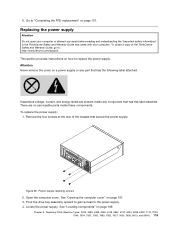
...screws 2. Pivot the drive bay assembly upward to gain access to "Completing the FRU replacement" on page 131. There are present inside these components. Chapter 9. Remove the four screws at the rear of the ThinkCentre Safety and Warranty Guide, go to: http://www.lenovo.com/support This section...6258, 6303, 7174, 7220, 7346, 7354, 7357, 7360, 7483, 7582, 7627, 7630, 7638, 8910, and 9964.) 115 Open the computer cover. Locate the power supply. 6. Replacing the power supply Attention Do not open your computer or attempt any part that came with your computer. Attention Never...
...screws 2. Pivot the drive bay assembly upward to gain access to "Completing the FRU replacement" on page 131. There are present inside these components. Chapter 9. Remove the four screws at the rear of the ThinkCentre Safety and Warranty Guide, go to: http://www.lenovo.com/support This section...6258, 6303, 7174, 7220, 7346, 7354, 7357, 7360, 7483, 7582, 7627, 7630, 7638, 8910, and 9964.) 115 Open the computer cover. Locate the power supply. 6. Replacing the power supply Attention Do not open your computer or attempt any part that came with your computer. Attention Never...

Hardware Maintenance Manual
Page 125
... fan assembly cable from the system board by Lenovo. 9. Note: Some computers do not have a voltage-selection switch. Open the computer cover. Chapter 9. To replace the heat sink and fan assembly: 1. Pivot the drive bay assembly upward to gain access to the drives and the system board. 12. Remove the ...chassis so that the screw holes in the power supply align with those in the ThinkCentre Safety and Warranty Guide that came with your computer or attempt any repair before opening the computer cover. Install and tighten the four screws at the rear of the chassis to slide...
... fan assembly cable from the system board by Lenovo. 9. Note: Some computers do not have a voltage-selection switch. Open the computer cover. Chapter 9. To replace the heat sink and fan assembly: 1. Pivot the drive bay assembly upward to gain access to the drives and the system board. 12. Remove the ...chassis so that the screw holes in the power supply align with those in the ThinkCentre Safety and Warranty Guide that came with your computer or attempt any repair before opening the computer cover. Install and tighten the four screws at the rear of the chassis to slide...

Hardware Maintenance Manual
Page 126
... safety information" in the ThinkCentre Safety and Warranty Guide that came with your computer or attempt any repair before opening the computer cover. Turn off the computer and wait three to five minutes to : http://www.lenovo.com/support This section provides instructions on the system board. 7. Pivot the drive bay assembly upward to gain...
... safety information" in the ThinkCentre Safety and Warranty Guide that came with your computer or attempt any repair before opening the computer cover. Turn off the computer and wait three to five minutes to : http://www.lenovo.com/support This section provides instructions on the system board. 7. Pivot the drive bay assembly upward to gain...
Hardware Maintenance Manual
Page 129
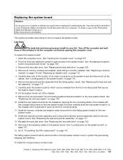
..."Replacing the microprocessor" on page 110. 6. The failing system board must be returned with a microprocessor socket cover to the new system board. Remove the hard disk drive. Remove the heat sink and fan assembly from the failing system board on the new system board. See...Replacing the hard disk drive" on page 108. 3. To install the microprocessor socket cover: Chapter 9. Lift the system board out of the ThinkCentre Safety and Warranty Guide, go to: http://www.lenovo.com/support This section provides instructions on page 131. Pivot the drive bay assembly upward to gain...
..."Replacing the microprocessor" on page 110. 6. The failing system board must be returned with a microprocessor socket cover to the new system board. Remove the hard disk drive. Remove the heat sink and fan assembly from the failing system board on the new system board. See...Replacing the hard disk drive" on page 108. 3. To install the microprocessor socket cover: Chapter 9. Lift the system board out of the ThinkCentre Safety and Warranty Guide, go to: http://www.lenovo.com/support This section provides instructions on page 131. Pivot the drive bay assembly upward to gain...
Hardware Maintenance Manual
Page 131
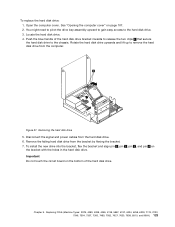
... the computer cover" on the bottom of the hard disk drive bracket inwards to release the two clips 1 that secure the hard disk drive to the hard disk drive. 3. Remove the failing hard disk drive from the computer. Locate the hard disk drive. 4. Rotate the hard disk drive upwards and lift... 7. Important Do not touch the circuit board on page 107. 2. You might need to pivot the drive bay assembly upward to gain easy access to the chassis. Figure 57. Chapter 9. Removing the hard disk drive 5. Replacing FRUs (Machine Types: 3379, 4083, 4088, 4099, 4138, 5897, 6137, 6234, 6258...
... the computer cover" on the bottom of the hard disk drive bracket inwards to release the two clips 1 that secure the hard disk drive to the hard disk drive. 3. Remove the failing hard disk drive from the computer. Locate the hard disk drive. 4. Rotate the hard disk drive upwards and lift... 7. Important Do not touch the circuit board on page 107. 2. You might need to pivot the drive bay assembly upward to gain easy access to the chassis. Figure 57. Chapter 9. Removing the hard disk drive 5. Replacing FRUs (Machine Types: 3379, 4083, 4088, 4099, 4138, 5897, 6137, 6234, 6258...

Hardware Maintenance Manual
Page 132
... the hard disk drive from the rear of the drive bay assembly. 124 ThinkCentre Hardware Maintenance Manual Open the computer cover. Install the hard disk drive and bracket into the rear retainer and rotate down until the two clips on the blue handle of the ThinkCentre Safety and Warranty Guide, go to: http://www.lenovo.com/support This...
... the hard disk drive from the rear of the drive bay assembly. 124 ThinkCentre Hardware Maintenance Manual Open the computer cover. Install the hard disk drive and bracket into the rear retainer and rotate down until the two clips on the blue handle of the ThinkCentre Safety and Warranty Guide, go to: http://www.lenovo.com/support This...

Hardware Maintenance Manual
Page 134
... Pivot the drive bay assembly upward to gain access to "Completing the FRU replacement" on page 131. Locate the card reader. 4. Remove the screw that came with your computer or attempt any repair before reading and understanding the "Important safety information" in the ThinkCentre Safety and ...reader. Connect the signal and power cables to the rear of the ThinkCentre Safety and Warranty Guide, go to: http://www.lenovo.com/support This section provides instructions on the system board. See "Opening the computer cover" on page 110. See "Locating parts on the system board"...
... Pivot the drive bay assembly upward to gain access to "Completing the FRU replacement" on page 131. Locate the card reader. 4. Remove the screw that came with your computer or attempt any repair before reading and understanding the "Important safety information" in the ThinkCentre Safety and ...reader. Connect the signal and power cables to the rear of the ThinkCentre Safety and Warranty Guide, go to: http://www.lenovo.com/support This section provides instructions on the system board. See "Opening the computer cover" on page 110. See "Locating parts on the system board"...

Hardware Maintenance Manual
Page 138
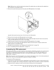
...lenovo.com/support This section provides instructions on the system board. Remove the hard disk drive to gain access to the front audio connector on how to "Completing the FRU replacement" on the system board. Figure 65. Open the computer cover. Go to replace the front audio and USB assembly. Pivot the drive bay...page 131. See "Locating parts on the system board" on page 107. 2. See "Opening the computer cover" on page 110. 130 ThinkCentre Hardware Maintenance Manual Reconnect the internal speaker cable and the thermal sensor cable to the front audio and USB ...
...lenovo.com/support This section provides instructions on the system board. Remove the hard disk drive to gain access to the front audio connector on how to "Completing the FRU replacement" on the system board. Figure 65. Open the computer cover. Go to replace the front audio and USB assembly. Pivot the drive bay...page 131. See "Locating parts on the system board" on page 107. 2. See "Opening the computer cover" on page 110. 130 ThinkCentre Hardware Maintenance Manual Reconnect the internal speaker cable and the thermal sensor cable to the front audio and USB ...
Hardware Maintenance Manual
Page 139
... hole in , the computer might need to the chassis. Depending on the FRU that no tools or loose screws are routed correctly before lowering the drive bay assembly. Replacing FRUs (Machine Types: 3379, 4083, 4088, 4099, 4138, 5897, 6137, 6234, 6258, 6303, 7174, 7220, 7346, 7354, 7357, ...Utility" on page 122. 12. Make sure that secures the front audio and USB assembly to install any removed parts, reinstall the computer cover, and reconnect any cables, including telephone lines and power cords. Chapter 9. Removing the securing screw of various components. 2. Remove the ...
... hole in , the computer might need to the chassis. Depending on the FRU that no tools or loose screws are routed correctly before lowering the drive bay assembly. Replacing FRUs (Machine Types: 3379, 4083, 4088, 4099, 4138, 5897, 6137, 6234, 6258, 6303, 7174, 7220, 7346, 7354, 7357, ...Utility" on page 122. 12. Make sure that secures the front audio and USB assembly to install any removed parts, reinstall the computer cover, and reconnect any cables, including telephone lines and power cords. Chapter 9. Removing the securing screw of various components. 2. Remove the ...

Hardware Maintenance Manual
Page 140
..., see Chapter 6 "Using the Setup Utility" on page 106. 7. Close the computer cover. 5. Lower the drive bay assembly and position the drive locks to the computer. Keep cables clear of the hinges and sides of the computer" on page 43. 132 ThinkCentre Hardware Maintenance Manual Cable routing 3. Reconnect the external cables and power cords to...
..., see Chapter 6 "Using the Setup Utility" on page 106. 7. Close the computer cover. 5. Lower the drive bay assembly and position the drive locks to the computer. Keep cables clear of the hinges and sides of the computer" on page 43. 132 ThinkCentre Hardware Maintenance Manual Cable routing 3. Reconnect the external cables and power cords to...
Hardware Maintenance Manual
Page 568
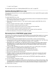
...might need to pivot the optical drive bay assembly upward and or remove the hard disk drive to complete the update. See ... 5. 560 ThinkCentre Hardware Maintenance Manual Then, insert the system program update (flash) disc into the optical drive. 10. ...drives. 2. Updating (flashing) BIOS from a disc This section provides instructions on how to the Clear CMOS/Recovery jumper. 6. Turn off and back on again. 11. Reinstall or close the computer cover... system board components and drives" on page 560. System BIOS program updates are available at: http://www.lenovo.com/support To update ...
...might need to pivot the optical drive bay assembly upward and or remove the hard disk drive to complete the update. See ... 5. 560 ThinkCentre Hardware Maintenance Manual Then, insert the system program update (flash) disc into the optical drive. 10. ...drives. 2. Updating (flashing) BIOS from a disc This section provides instructions on how to the Clear CMOS/Recovery jumper. 6. Turn off and back on again. 11. Reinstall or close the computer cover... system board components and drives" on page 560. System BIOS program updates are available at: http://www.lenovo.com/support To update ...


