Hardware Maintenance Manual
Page 5
...USB assembly . . 76 Replacing the heat sink 77 Replacing the microprocessor 78 Replacing the system board 80 Replacing the system fan 83 Replacing the hard disk drive 85 Replacing the optical drive 86 Replacing the internal speaker 88 Completing the FRU replacement ...Productivity Center 30 Access Help 30 Additional information resources 31 Specifications 31 Chapter 4. Diagnostic programs . . . 37 Lenovo ThinkVantage Toolbox 37 Lenovo Solution Center 37 Lenovo System Toolbox 38 PC-Doctor for Rescue and Recovery 38 PC-Doctor for power problems 33 Problem determination tips 34...
...USB assembly . . 76 Replacing the heat sink 77 Replacing the microprocessor 78 Replacing the system board 80 Replacing the system fan 83 Replacing the hard disk drive 85 Replacing the optical drive 86 Replacing the internal speaker 88 Completing the FRU replacement ...Productivity Center 30 Access Help 30 Additional information resources 31 Specifications 31 Chapter 4. Diagnostic programs . . . 37 Lenovo ThinkVantage Toolbox 37 Lenovo Solution Center 37 Lenovo System Toolbox 38 PC-Doctor for Rescue and Recovery 38 PC-Doctor for power problems 33 Problem determination tips 34...
Hardware Maintenance Manual
Page 10
...Examples of maintenance information. Power supply units - Use caution; Remember: Another person must be there to get medical aid. 4 ThinkCentre Hardware Maintenance Manual By observing the above rule, you work alone under hazardous conditions or near their normal operating places in the...you may prevent a current from their equipment, rubber floor mats that another person to switch off controls, is conductive; Blowers and fans - Switch off (EPO) switch, disconnecting switch, or electrical outlet. If an electrical accident occurs, you need to power-off...
...Examples of maintenance information. Power supply units - Use caution; Remember: Another person must be there to get medical aid. 4 ThinkCentre Hardware Maintenance Manual By observing the above rule, you work alone under hazardous conditions or near their normal operating places in the...you may prevent a current from their equipment, rubber floor mats that another person to switch off controls, is conductive; Blowers and fans - Switch off (EPO) switch, disconnecting switch, or electrical outlet. If an electrical accident occurs, you need to power-off...
Hardware Maintenance Manual
Page 67
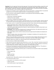
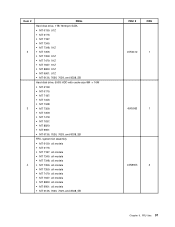
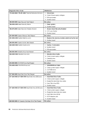
... Test Passed 185-XXX-XXX Asset Security failure 185-278-XXX Asset Security Chassis Intrusion 201-000-XXX System Memory Test Passed FRU/Action 1. Check fans 2. System board No action 1. See "Updating (flashing) BIOS from a disc" on page 43 2.
... Test Passed 185-XXX-XXX Asset Security failure 185-278-XXX Asset Security Chassis Intrusion 201-000-XXX System Memory Test Passed FRU/Action 1. Check fans 2. System board No action 1. See "Updating (flashing) BIOS from a disc" on page 43 2.

Hardware Maintenance Manual
Page 71
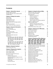
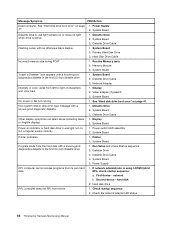
... Power Adapter 2. Video adapter (if present) 3. Diskette Drive 2. System Board 3. Network adapter (advise network administrator of characters and color bars 1. System Board No power or fan not running 1. System Board Diskette drive in -use light remains on or does not light when drive is using correct MAC address 5. Diskette Drive Cable...
... Power Adapter 2. Video adapter (if present) 3. Diskette Drive 2. System Board 3. Network adapter (advise network administrator of characters and color bars 1. System Board No power or fan not running 1. System Board Diskette drive in -use light remains on or does not light when drive is using correct MAC address 5. Diskette Drive Cable...
Hardware Maintenance Manual
Page 75
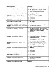
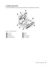
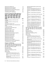
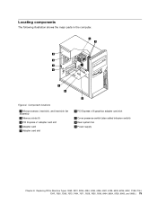
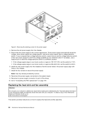
Component locations 1 Optical drive 2 Front bezel 3 Hard disk drive 4 System fan assembly 5 Heat sink 6 Battery 7 Memory slots (2) 8 Internal speaker Chapter 8. Figure 3. Replacing FRUs 69 Locating components The following illustration shows the locations of the various components in the computer.
Component locations 1 Optical drive 2 Front bezel 3 Hard disk drive 4 System fan assembly 5 Heat sink 6 Battery 7 Memory slots (2) 8 Internal speaker Chapter 8. Figure 3. Replacing FRUs 69 Locating components The following illustration shows the locations of the various components in the computer.
Hardware Maintenance Manual
Page 76
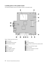
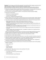
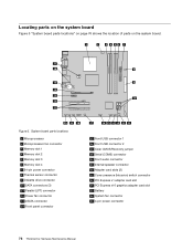
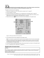
Figure 4. Locating parts on the system board The following illustration shows the locations of parts on the system board. System board parts locations 1 Microprocessor 2 Clear CMOS/Recovery jumper 3 Thermal sensor connector 4 Battery 5 Memory slots (2) 6 Internal speaker connector 7 Serial (COM) connector 8 SATA connectors (2) 9 PCI slot 10 Front USB connector 2 11 Intrusion switch connector/Cover presence switch connector 12 Front I/O and LED/Switch header 13 eSATA connector 14 Internal power distribution connector 15 System fan connector 70 ThinkCentre Hardware Maintenance Manual
Figure 4. Locating parts on the system board The following illustration shows the locations of parts on the system board. System board parts locations 1 Microprocessor 2 Clear CMOS/Recovery jumper 3 Thermal sensor connector 4 Battery 5 Memory slots (2) 6 Internal speaker connector 7 Serial (COM) connector 8 SATA connectors (2) 9 PCI slot 10 Front USB connector 2 11 Intrusion switch connector/Cover presence switch connector 12 Front I/O and LED/Switch header 13 eSATA connector 14 Internal power distribution connector 15 System fan connector 70 ThinkCentre Hardware Maintenance Manual
Hardware Maintenance Manual
Page 89
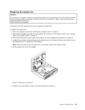
... heat sink to gain access to the chassis. Note: When you receive the new system fan, you will also receive new rubber mounts. 5. Lift the system fan out of the ThinkCentre Safety and Warranty Guide, go to: http://www.lenovo.com/support This section provides instructions on page 77. 4. See "Opening the computer cover...
... heat sink to gain access to the chassis. Note: When you receive the new system fan, you will also receive new rubber mounts. 5. Lift the system fan out of the ThinkCentre Safety and Warranty Guide, go to: http://www.lenovo.com/support This section provides instructions on page 77. 4. See "Opening the computer cover...
Hardware Maintenance Manual
Page 90
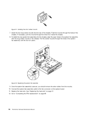
... the chassis. 8. Replacing the system fan assembly 9. If necessary, pull the mounts through the holes of the chassis. See "Replacing the heat sink" on page 89. 84 ThinkCentre Hardware Maintenance Manual Figure 21. Figure 22. Once the system fan assembly is in the chassis. Installing ...the short rubber mounts 7. Connect the system fan assembly cable to "Completing the FRU replacement" on page 77. 12...
... the chassis. 8. Replacing the system fan assembly 9. If necessary, pull the mounts through the holes of the chassis. See "Replacing the heat sink" on page 89. 84 ThinkCentre Hardware Maintenance Manual Figure 21. Figure 22. Once the system fan assembly is in the chassis. Installing ...the short rubber mounts 7. Connect the system fan assembly cable to "Completing the FRU replacement" on page 77. 12...
Hardware Maintenance Manual
Page 103
... 7356: • MT 7359: • MT 7479: • MT 7637: • MT 8820: • MT 9961: • MT 6136, 7626, 7629, and 8338_SB FRU, system fan assembly • MT 6139: all models • MT 6175: • MT 7187: all models • MT 7345: all models • MT 7348: all models •...
... 7356: • MT 7359: • MT 7479: • MT 7637: • MT 8820: • MT 9961: • MT 6136, 7626, 7629, and 8338_SB FRU, system fan assembly • MT 6139: all models • MT 6175: • MT 7187: all models • MT 7345: all models • MT 7348: all models •...
Hardware Maintenance Manual
Page 5
... the front bezel . . . . 77 Replacing a memory module 78 Replacing the power supply 79 Replacing the heat sink and fan assembly . . . . 80 Replacing the microprocessor 81 Replacing the system board 84 Replacing the battery 86 Replacing an adapter card ... disk drive . . . . 92 Replacing the optical drive 94 iii General information . . . . 29 Online Books folder 29 Lenovo ThinkVantage Tools 29 SimpleTap 30 Lenovo Solution Center 30 ThinkVantage Productivity Center 30 Access Help 30 Additional information resources 31 Specifications 32 For machine types: 3063, 3231, 3285, ...
... the front bezel . . . . 77 Replacing a memory module 78 Replacing the power supply 79 Replacing the heat sink and fan assembly . . . . 80 Replacing the microprocessor 81 Replacing the system board 84 Replacing the battery 86 Replacing an adapter card ... disk drive . . . . 92 Replacing the optical drive 94 iii General information . . . . 29 Online Books folder 29 Lenovo ThinkVantage Tools 29 SimpleTap 30 Lenovo Solution Center 30 ThinkVantage Productivity Center 30 Access Help 30 Additional information resources 31 Specifications 32 For machine types: 3063, 3231, 3285, ...
Hardware Maintenance Manual
Page 6
... CD 514 Windows 7 Professional 32 Recovery CD . . 519 Windows 7 Professional 32 SP1 Recovery CD 529 Windows 7 Professional 64 Recovery CD . . 539 iv ThinkCentre Hardware Maintenance Manual Replacing FRUs (Machine Types: 3379, 4083, 4088, 4099, 4138, 5897, 6137, 6234, 6258, 6303, 7174, 7220, 7346, 7354, 7357...Replacing the battery 110 Replacing a memory module 112 Replacing an adapter card 113 Replacing the power supply 115 Replacing the heat sink and fan assembly . . . . 117 Replacing the microprocessor 118 Replacing the system board 121 Replacing the hard disk drive 122 Replacing the ...
... CD 514 Windows 7 Professional 32 Recovery CD . . 519 Windows 7 Professional 32 SP1 Recovery CD 529 Windows 7 Professional 64 Recovery CD . . 539 iv ThinkCentre Hardware Maintenance Manual Replacing FRUs (Machine Types: 3379, 4083, 4088, 4099, 4138, 5897, 6137, 6234, 6258, 6303, 7174, 7220, 7346, 7354, 7357...Replacing the battery 110 Replacing a memory module 112 Replacing an adapter card 113 Replacing the power supply 115 Replacing the heat sink and fan assembly . . . . 117 Replacing the microprocessor 118 Replacing the system board 121 Replacing the hard disk drive 122 Replacing the ...
Hardware Maintenance Manual
Page 12
... precautions when you can cause personal injury and machine damage. • Do not service the following precautions: - these hazards are removed from a circuit. Blowers and fans - do not become a victim yourself. - Performing a mechanical inspection - Ensure that has hazardous voltages. • Disconnect all power before: - Stand on the machine, unplug the power... metal floor strips and machine frames. Send another person, familiar with powered-on a machine that supplies power to the machine and to get medical aid. 4 ThinkCentre Hardware Maintenance Manual
... precautions when you can cause personal injury and machine damage. • Do not service the following precautions: - these hazards are removed from a circuit. Blowers and fans - do not become a victim yourself. - Performing a mechanical inspection - Ensure that has hazardous voltages. • Disconnect all power before: - Stand on the machine, unplug the power... metal floor strips and machine frames. Send another person, familiar with powered-on a machine that supplies power to the machine and to get medical aid. 4 ThinkCentre Hardware Maintenance Manual
Hardware Maintenance Manual
Page 72
Microprocessor 4. Diskette Drive Cable 2. Reseat the hard disk drive cable 4. System board 1. Hard Disk drive (SCSI) 5. Check fans 2. Flash system 2. System board No action 1. System board 3. Diskette drive 4. CD-ROM drive 4. System board No action 1. Hard ...1. CD-ROM Drive Cable 2. Hard Disk Drive Cable 2. Cache, if removable 2. Check power supply voltages 3. System board No action 64 ThinkCentre Hardware Maintenance Manual Check power supply voltages 3. Check power supply voltages 3. Diagnostic Error Code 175-250-XXX 175-251-XXX Thermal Sensor(s) limit...
Microprocessor 4. Diskette Drive Cable 2. Reseat the hard disk drive cable 4. System board 1. Hard Disk drive (SCSI) 5. Check fans 2. Flash system 2. System board No action 1. System board 3. Diskette drive 4. CD-ROM drive 4. System board No action 1. Hard ...1. CD-ROM Drive Cable 2. Hard Disk Drive Cable 2. Cache, if removable 2. Check power supply voltages 3. System board No action 64 ThinkCentre Hardware Maintenance Manual Check power supply voltages 3. Check power supply voltages 3. Diagnostic Error Code 175-250-XXX 175-251-XXX Thermal Sensor(s) limit...
Hardware Maintenance Manual
Page 76
... computer cannot access programs from server 1. Hard disk drive RPL computer does not RPL from its own hard 1. Check the network adapter LED status 68 ThinkCentre Hardware Maintenance Manual Diskette Drive 2. System Board 2. Hard Disk Drive Cable Incorrect memory size during POST 1. Diskette Drive Cable 3. Network Adapter Intensity or color varies... of characters and color bars 1. System Board Diskette drive in -use light remains on , but computer works correctly 1. System Board 3. System Board No power or fan not running 1.
... computer cannot access programs from server 1. Hard disk drive RPL computer does not RPL from its own hard 1. Check the network adapter LED status 68 ThinkCentre Hardware Maintenance Manual Diskette Drive 2. System Board 2. Hard Disk Drive Cable Incorrect memory size during POST 1. Diskette Drive Cable 3. Network Adapter Intensity or color varies... of characters and color bars 1. System Board Diskette drive in -use light remains on , but computer works correctly 1. System Board 3. System Board No power or fan not running 1.
Hardware Maintenance Manual
Page 83
..., 7347, 7355, 7358, 7373, 7484, 7571, 7628, 7635, 7639, 8494, 8854, 9728, 9960, and 9965.) 75 Figure 4. Component locations 1 Microprocessor, heat sink, and heat sink fan assembly 2 Memory slots (4) 3 PCI Express x1 adapter card slot 4 Adapter card 5 Adapter card slot 6 PCI Express x16 graphics adapter card slot 7 Cover presence switch (also...
..., 7347, 7355, 7358, 7373, 7484, 7571, 7628, 7635, 7639, 8494, 8854, 9728, 9960, and 9965.) 75 Figure 4. Component locations 1 Microprocessor, heat sink, and heat sink fan assembly 2 Memory slots (4) 3 PCI Express x1 adapter card slot 4 Adapter card 5 Adapter card slot 6 PCI Express x16 graphics adapter card slot 7 Cover presence switch (also...
Hardware Maintenance Manual
Page 84
... board Figure 5 "System board parts locations" on page 76 shows the location of parts on the system board. Figure 5. System board parts locations 1 Microprocessor 2 Microprocessor fan connector 3 Memory slot 1 4 Memory slot 2 5 Memory slot 3 6 Memory slot 4 7 24-pin power connector 8 Thermal sensor connector 9 Diskette drive connector 10 SATA connectors (3) 11 ... Cover presence (Intrusion) switch connector 23 PCI Express x1 adapter card slot 24 PCI Express x16 graphics adapter card slot 25 Battery 26 System fan connector 27 4-pin power connector 76 ThinkCentre Hardware Maintenance Manual
... board Figure 5 "System board parts locations" on page 76 shows the location of parts on the system board. Figure 5. System board parts locations 1 Microprocessor 2 Microprocessor fan connector 3 Memory slot 1 4 Memory slot 2 5 Memory slot 3 6 Memory slot 4 7 24-pin power connector 8 Thermal sensor connector 9 Diskette drive connector 10 SATA connectors (3) 11 ... Cover presence (Intrusion) switch connector 23 PCI Express x1 adapter card slot 24 PCI Express x16 graphics adapter card slot 25 Battery 26 System fan connector 27 4-pin power connector 76 ThinkCentre Hardware Maintenance Manual
Hardware Maintenance Manual
Page 88
... connectors to secure the power supply. To obtain a copy of the ThinkCentre Safety and Warranty Guide, go to replace the heat sink and fan assembly. 80 ThinkCentre Hardware Maintenance Manual Note: Use only screws provided by Lenovo. 8. Go to "Completing the FRU replacement" on how to : http...://www.lenovo.com/support This section provides instructions on page 103. If your...
... connectors to secure the power supply. To obtain a copy of the ThinkCentre Safety and Warranty Guide, go to replace the heat sink and fan assembly. 80 ThinkCentre Hardware Maintenance Manual Note: Use only screws provided by Lenovo. 8. Go to "Completing the FRU replacement" on how to : http...://www.lenovo.com/support This section provides instructions on page 103. If your...
Hardware Maintenance Manual
Page 89
... reading and understanding the "Important safety information" in the ThinkCentre Safety and Warranty Guide that the four screws are aligned with your computer or attempt any repair before removing the computer cover. Connect the heat sink and fan assembly cable to the system board. 8. Replacing FRUs (...bracket so that came with the posts on the system board. Go to : http://www.lenovo.com/support Chapter 8. To replace the heat sink and fan assembly: 1. To obtain a copy of the ThinkCentre Safety and Warranty Guide, go to "Completing the FRU replacement" on page 103. Lay ...
... reading and understanding the "Important safety information" in the ThinkCentre Safety and Warranty Guide that the four screws are aligned with your computer or attempt any repair before removing the computer cover. Connect the heat sink and fan assembly cable to the system board. 8. Replacing FRUs (...bracket so that came with the posts on the system board. Go to : http://www.lenovo.com/support Chapter 8. To replace the heat sink and fan assembly: 1. To obtain a copy of the ThinkCentre Safety and Warranty Guide, go to "Completing the FRU replacement" on page 103. Lay ...
Hardware Maintenance Manual
Page 90
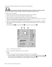
...computer cover. Remove any parts or cables that the thermal grease does not come in the socket. Disconnect the heat sink and fan assembly cable from the one corner of the microprocessor or note the orientation of the notches 2 on one illustrated. See "Replacing... the heat sink and fan assembly" on the system board. 82 ThinkCentre Hardware Maintenance Manual Accessing the microprocessor 8. Lift the microprocessor straight up and out of the microprocessor in contact with anything...
...computer cover. Remove any parts or cables that the thermal grease does not come in the socket. Disconnect the heat sink and fan assembly cable from the one corner of the microprocessor or note the orientation of the notches 2 on one illustrated. See "Replacing... the heat sink and fan assembly" on the system board. 82 ThinkCentre Hardware Maintenance Manual Accessing the microprocessor 8. Lift the microprocessor straight up and out of the microprocessor in contact with anything...
Hardware Maintenance Manual
Page 91
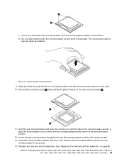
Lower the new microprocessor straight down into position with the corresponding beveled corner of the microprocessor. Reinstall the heat sink and fan assembly. Do not drop anything onto the microprocessor socket while it is fully open. 10. Removing the microprocessor 9. Remove the protective cover 2 ... the gold contacts on the system board. 13. Touch only the sides of the microprocessor socket. 12. See "Replacing the heat sink and fan assembly" on the bottom. Do not touch the gold contacts on page 80. Hold the new microprocessor and align the notches on it into ...
Lower the new microprocessor straight down into position with the corresponding beveled corner of the microprocessor. Reinstall the heat sink and fan assembly. Do not drop anything onto the microprocessor socket while it is fully open. 10. Removing the microprocessor 9. Remove the protective cover 2 ... the gold contacts on the system board. 13. Touch only the sides of the microprocessor socket. 12. See "Replacing the heat sink and fan assembly" on the bottom. Do not touch the gold contacts on page 80. Hold the new microprocessor and align the notches on it into ...


