User Manual
Page 5
...ix CD and DVD drive safety ix Additional safety information x Lithium battery notice x Modem safety information xi Laser compliance statement xi Power supply statement xii Introduction xiii Chapter 1. Setting up your computer . . 3 Connecting your computer 3 Turning on the system board .... . . 23 Installing memory 24 Installing PCI adapters 25 Installing internal drives 27 Drive specifications 28 Installing a drive in bay 1 29 © Lenovo 2005, 2006. Updating system programs 53 Using system programs 53 Updating (flashing) BIOS from the Setup Utility program . . . . . 51 ...
...ix CD and DVD drive safety ix Additional safety information x Lithium battery notice x Modem safety information xi Laser compliance statement xi Power supply statement xii Introduction xiii Chapter 1. Setting up your computer . . 3 Connecting your computer 3 Turning on the system board .... . . 23 Installing memory 24 Installing PCI adapters 25 Installing internal drives 27 Drive specifications 28 Installing a drive in bay 1 29 © Lenovo 2005, 2006. Updating system programs 53 Using system programs 53 Updating (flashing) BIOS from the Setup Utility program . . . . . 51 ...
User Manual
Page 8
... required for or by the customer. Lenovo expressly identifies CRUs as Customer Replaceable Units, or CRUs. v The product does not operate normally when you follow all instructions when performing such replacements. For more information on the battery. v Power cords, plugs, power adapters, extension cords, surge protectors, or power supplies that liquid has been spilled or...
... required for or by the customer. Lenovo expressly identifies CRUs as Customer Replaceable Units, or CRUs. v The product does not operate normally when you follow all instructions when performing such replacements. For more information on the battery. v Power cords, plugs, power adapters, extension cords, surge protectors, or power supplies that liquid has been spilled or...
User Manual
Page 10
...electrician for more information if you have questions about power loads and branch circuit ratings. Batteries supplied by Lenovo for use are rated to insert it is replaced by Lenovo contain a non-rechargeable coin cell battery to provide power to water or other liquids. Do not expose the...overheat, which could increase the risk of time. Extension cords and related devices Ensure that extension cords, surge protectors, uninterruptible power supplies, and power strips that you use with your product have been tested for compatibility and should only be damaged or corroded, do not ...
...electrician for more information if you have questions about power loads and branch circuit ratings. Batteries supplied by Lenovo for use are rated to insert it is replaced by Lenovo contain a non-rechargeable coin cell battery to provide power to water or other liquids. Do not expose the...overheat, which could increase the risk of time. Extension cords and related devices Ensure that extension cords, surge protectors, uninterruptible power supplies, and power strips that you use with your product have been tested for compatibility and should only be damaged or corroded, do not ...

User Manual
Page 11
... sunlight and away from vents and perforations in or near flammable materials or in . Before inspecting your computer, turn off the power and unplug the computer's power cord from vents and any part of high-traffic areas. v Regularly inspect the outside of the battery and can generate a ..., you must operate your computer in the bezel. v Always store CD and DVD discs out of the computer including heat sink inlet fins, power supply vents, and fans. then remove any ventilation openings. v Do not store or operate your computer more frequently. Do not let rechargeable Lithium-Ion...
... sunlight and away from vents and perforations in or near flammable materials or in . Before inspecting your computer, turn off the power and unplug the computer's power cord from vents and any part of high-traffic areas. v Regularly inspect the outside of the battery and can generate a ..., you must operate your computer in the bezel. v Always store CD and DVD discs out of the computer including heat sink inlet fins, power supply vents, and fans. then remove any ventilation openings. v Do not store or operate your computer more frequently. Do not let rechargeable Lithium-Ion...
User Manual
Page 14
xii User Guide Hazardous voltage, current, and energy levels are no serviceable parts inside any part that has this label attached. If you suspect a problem with one of these components. There are present inside these parts, contact a service technician. Power supply statement Never remove the cover on a power supply or any component that has the following label attached.
xii User Guide Hazardous voltage, current, and energy levels are no serviceable parts inside any part that has this label attached. If you suspect a problem with one of these components. There are present inside these parts, contact a service technician. Power supply statement Never remove the cover on a power supply or any component that has the following label attached.
User Manual
Page 29
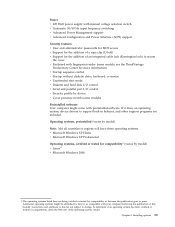
...systems. v Microsoft Windows XP Home v Microsoft Windows XP Professional Operating systems, certified or tested for compatibility1 (varies by Lenovo as compatible with your computer following the publication of this publication goes to change. If it does, an operating system...compatibility, check the Web site of the operating system vendor. Power v 225 Watt power supply with manual voltage selection switch v Automatic 50/60 Hz input frequency switching v Advanced Power Management support v Advanced Configuration and Power Interface (ACPI) support Security features v User and administrator ...
...systems. v Microsoft Windows XP Home v Microsoft Windows XP Professional Operating systems, certified or tested for compatibility1 (varies by Lenovo as compatible with your computer following the publication of this publication goes to change. If it does, an operating system...compatibility, check the Web site of the operating system vendor. Power v 225 Watt power supply with manual voltage selection switch v Automatic 50/60 Hz input frequency switching v Advanced Power Management support v Advanced Configuration and Power Interface (ACPI) support Security features v User and administrator ...

User Manual
Page 35
Installing options 19 Chapter 3. Locating connectors on the rear of your computer The following illustration shows locations of connectors on the rear of your computer. 1 Power cord connector 2 Rope clip holes 3 Serial connector (some models) 4 Integrated cable lock 5 PCI adapter connector 6 PCI adapter connector 7 Ethernet connector...line out connector 14 Audio line in connector 15 PCI Express (x16) graphics adapter connector (some models) 16 Power supply diagnostic LEDs Note: Some connectors on the rear of your computer are color-coded to help determine where to connect the cables.
Installing options 19 Chapter 3. Locating connectors on the rear of your computer The following illustration shows locations of connectors on the rear of your computer. 1 Power cord connector 2 Rope clip holes 3 Serial connector (some models) 4 Integrated cable lock 5 PCI adapter connector 6 PCI adapter connector 7 Ethernet connector...line out connector 14 Audio line in connector 15 PCI Express (x16) graphics adapter connector (some models) 16 Power supply diagnostic LEDs Note: Some connectors on the rear of your computer are color-coded to help determine where to connect the cables.

User Manual
Page 38
Locating components The following illustration will help you locate the various components in your computer. 1 Power supply assembly 2 Internal speaker 3 Diskette drive 4 Optical drive 5 Hard disk drive 6 Microprocessor and heat sink 7 Memory module 8 PCI riser assembly 9 PCI Express (x16) graphics adapter connector 22 User Guide
Locating components The following illustration will help you locate the various components in your computer. 1 Power supply assembly 2 Internal speaker 3 Diskette drive 4 Optical drive 5 Hard disk drive 6 Microprocessor and heat sink 7 Memory module 8 PCI riser assembly 9 PCI Express (x16) graphics adapter connector 22 User Guide

User Manual
Page 39
... you can install later. Identifying parts on the system board. 1 Internal speaker connector 2 Serial connector 2 (COM2) 3 PCI Express (x16) graphics adapter connector 4 Power supply connector 5 Diskette drive connector 6 12v power connector 7 Temperature sensor connector 8 Microprocessor heat sink 9 Fan connector 1 10 Front panel connector 11 Microprocessor 12 Fan connector 2 13 Memory connector 1 14 Memory...
... you can install later. Identifying parts on the system board. 1 Internal speaker connector 2 Serial connector 2 (COM2) 3 PCI Express (x16) graphics adapter connector 4 Power supply connector 5 Diskette drive connector 6 12v power connector 7 Temperature sensor connector 8 Microprocessor heat sink 9 Fan connector 1 10 Front panel connector 11 Microprocessor 12 Fan connector 2 13 Memory connector 1 14 Memory...
Hardware Maintenance Manual
Page 5
... diagnostics programs . . 43 Running tests 43 © Copyright Lenovo 2008, 2010 Test results 44 Fixed disk advanced test (FDAT 44 Quick and Full erase - General Checkout. . . . . 37 Problem determination tips 38 Chapter 5. Symptom-to-FRU Index . 51 Hard disk drive boot error 51 Power Supply Errors 51 Diagnostic error codes 52 Beep symptoms...
... diagnostics programs . . 43 Running tests 43 © Copyright Lenovo 2008, 2010 Test results 44 Fixed disk advanced test (FDAT 44 Quick and Full erase - General Checkout. . . . . 37 Problem determination tips 38 Chapter 5. Symptom-to-FRU Index . 51 Hard disk drive boot error 51 Power Supply Errors 51 Diagnostic error codes 52 Beep symptoms...

Hardware Maintenance Manual
Page 12
..., rubber floor mats that supplies power to the machine and to power-off (EPO) switch, disconnecting switch, or electrical outlet. Power supply units - Use only one hand when working with live electrical circuits with powered-on the machine, unplug the power cord. By observing the above... rule, you cannot unplug it has been powered-off the power, if necessary. - Observe the ...
..., rubber floor mats that supplies power to the machine and to power-off (EPO) switch, disconnecting switch, or electrical outlet. Power supply units - Use only one hand when working with live electrical circuits with powered-on the machine, unplug the power cord. By observing the above... rule, you cannot unplug it has been powered-off the power, if necessary. - Observe the ...

Hardware Maintenance Manual
Page 13
... hazards due to eliminate static on these conditions and the safety hazards they exceed the requirements noted here. 2. Check that the power-supply cover fasteners (screws or rivets) have been certified (ISO 9000) as it was designed and built, had required safety items ... devices you can continue without first correcting the problem. Safety inspection guide The intent of this inspection guide. Power-off , and the power cord disconnected. Checklist: 1. Disconnect the power cord. 3. Check inside the unit for damage (loose, broken, or sharp edges) 2. Check exterior covers...
... hazards due to eliminate static on these conditions and the safety hazards they exceed the requirements noted here. 2. Check that the power-supply cover fasteners (screws or rivets) have been certified (ISO 9000) as it was designed and built, had required safety items ... devices you can continue without first correcting the problem. Safety inspection guide The intent of this inspection guide. Power-off , and the power cord disconnected. Checklist: 1. Disconnect the power cord. 3. Check inside the unit for damage (loose, broken, or sharp edges) 2. Check exterior covers...

Hardware Maintenance Manual
Page 16
To remove all electrical current from the device, ensure that all power cords are disconnected from the power source. 2 1 10 Hardware Maintenance Manual CAUTION: The power control button on the device and the power switch on the power supply do not turn off the electrical current supplied to the device. ≥18 kg (37 lbs) ≥32 kg (70.5 lbs) ≥55 kg (121.2 lbs) CAUTION: Use safe practices when lifting. The device also might have more than one power cord.
To remove all electrical current from the device, ensure that all power cords are disconnected from the power source. 2 1 10 Hardware Maintenance Manual CAUTION: The power control button on the device and the power switch on the power supply do not turn off the electrical current supplied to the device. ≥18 kg (37 lbs) ≥32 kg (70.5 lbs) ≥55 kg (121.2 lbs) CAUTION: Use safe practices when lifting. The device also might have more than one power cord.
Hardware Maintenance Manual
Page 43
...program. Use the following table. © Copyright Lenovo 2008, 2010 37 If you did not receive the correct response, proceed to help you hear beep codes during write operations such as copying, saving, or formatting. a. Chapter 4. Set Power-On Self-Test to "POST error codes" ... if you are located on page 47. 2. If you do the following conditions and follow the instructions: • If you determine if the power supply and system board are detected by an application program, the operating system, or both. Set all external devices. 5. d. b. c. See "Starting...
...program. Use the following table. © Copyright Lenovo 2008, 2010 37 If you did not receive the correct response, proceed to help you hear beep codes during write operations such as copying, saving, or formatting. a. Chapter 4. Set Power-On Self-Test to "POST error codes" ... if you are located on page 47. 2. If you do the following conditions and follow the instructions: • If you determine if the power supply and system board are detected by an application program, the operating system, or both. Set all external devices. 5. d. b. c. See "Starting...
Hardware Maintenance Manual
Page 44
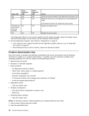
.... Problem determination tips Due to it failing? - BIOS level • Operating system software - Replace the system board ON Replace the power supply If the Diagnostic LEDs are considered identical only if they: 1. Is the failure repeatable? - Is this information available when requesting assistance ... level 38 Hardware Maintenance Manual What, when, where, single, or multiple systems? - Make sure the power cord is attached to a working , what changes were made prior to the variety of the LEDs when the power is OK, replace the power supply. Has this configuration ever worked? -
.... Problem determination tips Due to it failing? - BIOS level • Operating system software - Replace the system board ON Replace the power supply If the Diagnostic LEDs are considered identical only if they: 1. Is the failure repeatable? - Is this information available when requesting assistance ... level 38 Hardware Maintenance Manual What, when, where, single, or multiple systems? - Make sure the power cord is attached to a working , what changes were made prior to the variety of the LEDs when the power is OK, replace the power supply. Has this configuration ever worked? -

Hardware Maintenance Manual
Page 57
...proper installation. • Power Cord • On/Off Switch connector • On/Off Switch Power Supply connector • System Board Power Supply connectors • Microprocessor(s) connection Check the power cord for continuity. 1. Install an operating system on Switch © Copyright Lenovo 2008, 2010 51 The ... test, but did receive a POST error message, diagnose the POST error message first. • If you have the following procedures. Power Supply Errors If you replace a hard disk drive. Always begin with Chapter 4 "General Checkout" on the computer. The drive is listed...
...proper installation. • Power Cord • On/Off Switch connector • On/Off Switch Power Supply connector • System Board Power Supply connectors • Microprocessor(s) connection Check the power cord for continuity. 1. Install an operating system on Switch © Copyright Lenovo 2008, 2010 51 The ... test, but did receive a POST error message, diagnose the POST error message first. • If you have the following procedures. Power Supply Errors If you replace a hard disk drive. Always begin with Chapter 4 "General Checkout" on the computer. The drive is listed...
Hardware Maintenance Manual
Page 58
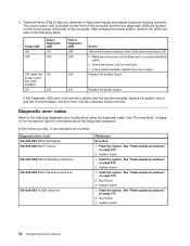
... board 1. Flash the system. Boot block 3. System board 1. System board 52 Hardware Maintenance Manual See "Running tests" on the power supply at a time, until the computer works correctly. See "Flash update procedures" on page 375 2. Replace the system board ON Replace the... power supply If the Diagnostic LEDs are working electrical outlet. • Check the power cord for information about the Diagnostic programs. In the following diagnostic error codes when using the diagnostic ...
... board 1. Flash the system. Boot block 3. System board 1. System board 52 Hardware Maintenance Manual See "Running tests" on the power supply at a time, until the computer works correctly. See "Flash update procedures" on page 375 2. Replace the system board ON Replace the... power supply If the Diagnostic LEDs are working electrical outlet. • Check the power cord for information about the Diagnostic programs. In the following diagnostic error codes when using the diagnostic ...

Hardware Maintenance Manual
Page 68
... the log file 1. Flash the system and re-test. Replace component under test 1. Riser card, if installed 3. IDE signal cable 2. Check power supply voltages 3. IDE device 5. Re-start the test to "Undetermined problems" on page 375 3. Re-run test 3. See "Flash update procedures" on...if necessary 1. Reseat IDE signal cable 4. Reseat IDE signal cable 4. See "Flash update procedures" on page 375 3. IDE device 5. Check power supply 3. If a component is connected and/or enabled. See "Flash update procedures" on page 375 3. Make sure the component that is called out...
... the log file 1. Flash the system and re-test. Replace component under test 1. Riser card, if installed 3. IDE signal cable 2. Check power supply voltages 3. IDE device 5. Re-start the test to "Undetermined problems" on page 375 3. Re-run test 3. See "Flash update procedures" on...if necessary 1. Reseat IDE signal cable 4. Reseat IDE signal cable 4. See "Flash update procedures" on page 375 3. IDE device 5. Check power supply 3. If a component is connected and/or enabled. See "Flash update procedures" on page 375 3. Make sure the component that is called out...

Hardware Maintenance Manual
Page 69
Re-run test 3. Go to review the log file 2. Replace component under test 1. SCSI signal cable 2. Check power supply 3. SCSI signal cable 2. See "Flash update procedures" on page 47 2. SCSI device 4. Replace the component under function test No action 1. See ...5. Press F3 to "Undetermined problems" on page 76 1. Go to -FRU Index 63 Flash the system. System board 1. SCSI signal cable 2. Check power supply 3. Symptom-to "Undetermined problems" on page 375 3. System board Information only Re-start the test to reset the log file Chapter 7. If a component ...
Re-run test 3. Go to review the log file 2. Replace component under test 1. SCSI signal cable 2. Check power supply 3. SCSI signal cable 2. See "Flash update procedures" on page 47 2. SCSI device 4. Replace the component under function test No action 1. See ...5. Press F3 to "Undetermined problems" on page 76 1. Go to -FRU Index 63 Flash the system. System board 1. SCSI signal cable 2. Check power supply 3. Symptom-to "Undetermined problems" on page 375 3. System board Information only Re-start the test to reset the log file Chapter 7. If a component ...

Hardware Maintenance Manual
Page 74
.... Voltage Regulator Module (VRM) 2. Replace the component that is called out in warning statement 4. See "Flash update procedures" on page 76 68 Hardware Maintenance Manual Power supply 2. Diagnostic Error Code 170-197-XXX Voltage Sensor(s) test warning 170-198-XXX Voltage Sensor(s) test aborted 170-199-XXX Voltage Sensor(s) test failed, cause...
.... Voltage Regulator Module (VRM) 2. Replace the component that is called out in warning statement 4. See "Flash update procedures" on page 76 68 Hardware Maintenance Manual Power supply 2. Diagnostic Error Code 170-197-XXX Voltage Sensor(s) test warning 170-198-XXX Voltage Sensor(s) test aborted 170-199-XXX Voltage Sensor(s) test failed, cause...


