
User Manual
Page 5
... a temporary startup device . . . . . 56 Changing the startup device sequence . . . . 56 Advanced settings 56 Chapter 7. Symptom-to-FRU Index . . . 57 Hard disk drive boot error 57 Power Supply Errors 57 Diagnostic error codes 59 Beep symptoms 80 No-beep symptoms 82 POST error codes 83 Miscellaneous error messages 86 Undetermined problems 88 Chapter... Recovery workspace 47 Starting PC-Doctor from the Setup Utility program . . . . . 53 Using passwords 53 Password considerations 54 User Password 54 Administrator Password 54 © Lenovo 2005, 2009. Contents Chapter 1.
... a temporary startup device . . . . . 56 Changing the startup device sequence . . . . 56 Advanced settings 56 Chapter 7. Symptom-to-FRU Index . . . 57 Hard disk drive boot error 57 Power Supply Errors 57 Diagnostic error codes 59 Beep symptoms 80 No-beep symptoms 82 POST error codes 83 Miscellaneous error messages 86 Undetermined problems 88 Chapter... Recovery workspace 47 Starting PC-Doctor from the Setup Utility program . . . . . 53 Using passwords 53 Password considerations 54 User Password 54 Administrator Password 54 © Lenovo 2005, 2009. Contents Chapter 1.

User Manual
Page 12
...wall box in your pocket or behind your electrical hand tools for that it , ask the customer to power-off the wall box that supplies power to the machine and to work on a machine that contain small conductive fibers to switch off position. ...the installation and configuration procedures. First, check that tester. - v Disconnect all power before you work alone under hazardous conditions or near power supplies - v Never assume that has hazardous voltages. v Find the room emergency power-off . 6 Hardware Maintenance Manual v Regularly inspect and maintain your back. ...
...wall box in your pocket or behind your electrical hand tools for that it , ask the customer to power-off the wall box that supplies power to the machine and to work on a machine that contain small conductive fibers to switch off position. ...the installation and configuration procedures. First, check that tester. - v Disconnect all power before you work alone under hazardous conditions or near power supplies - v Never assume that has hazardous voltages. v Find the room emergency power-off . 6 Hardware Maintenance Manual v Regularly inspect and maintain your back. ...

User Manual
Page 13
...Use a meter to attachment of steps presented in your work area. c. Examples of a plastic dental mirror. Use caution; Power-off power. - Disconnect the power cord. 3. Begin the checks with the reflective surface of these conditions and the safety hazards they are present, you must ...possible hazards in a checklist. This guide addresses only those items. However, good judgment should be and whether you in good condition. Power supply units - Safety inspection guide The intent of the units.) v If an electrical accident occurs: - v Always look carefully for 0.1...
...Use a meter to attachment of steps presented in your work area. c. Examples of a plastic dental mirror. Use caution; Power-off power. - Disconnect the power cord. 3. Begin the checks with the reflective surface of these conditions and the safety hazards they are present, you must ...possible hazards in a checklist. This guide addresses only those items. However, good judgment should be and whether you in good condition. Power supply units - Safety inspection guide The intent of the units.) v If an electrical accident occurs: - v Always look carefully for 0.1...
User Manual
Page 14
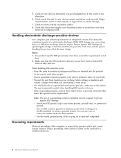
... with . Handling electrostatic discharge-sensitive devices Any computer part containing transistors or integrated circuits (ICs) should be verified by equalizing the charge so that the power-supply cover fasteners (screws or rivets) have been certified (ISO 9000) as to the safety of any obvious unsafe conditions, such as those listed below, to...
... with . Handling electrostatic discharge-sensitive devices Any computer part containing transistors or integrated circuits (ICs) should be verified by equalizing the charge so that the power-supply cover fasteners (screws or rivets) have been certified (ISO 9000) as to the safety of any obvious unsafe conditions, such as those listed below, to...

User Manual
Page 17
CAUTION: The power control button on the device and the power switch on the power supply do not turn off the electrical current supplied to the device. The device also might have more than one power cord. To remove all electrical current from the device, ensure that all power cords are disconnected from the power source. 2 1 Chapter 2. Safety information 11
CAUTION: The power control button on the device and the power switch on the power supply do not turn off the electrical current supplied to the device. The device also might have more than one power cord. To remove all electrical current from the device, ensure that all power cords are disconnected from the power source. 2 1 Chapter 2. Safety information 11
User Manual
Page 49
...of BIOS is displayed, continue at the following procedure to determine and obtain the latest level BIOS, see "BIOS levels" on the power supply at the rear of the computer. v If the computer hangs and no errors are servicing might cause false errors and unnecessary replacement ... installed on page 44. 6. For an explanation of the system board. Power-off the computer and all cables and power cords. 3. A power button LED is found by POST. If you select an incorrect drive. Press the power button. © Lenovo 2005, 2009. v To enable beep, memory count, and checkpoint code...
...of BIOS is displayed, continue at the following procedure to determine and obtain the latest level BIOS, see "BIOS levels" on the power supply at the rear of the computer. v If the computer hangs and no errors are servicing might cause false errors and unnecessary replacement ... installed on page 44. 6. For an explanation of the system board. Power-off the computer and all cables and power cords. 3. A power button LED is found by POST. If you select an incorrect drive. Press the power button. © Lenovo 2005, 2009. v To enable beep, memory count, and checkpoint code...
User Manual
Page 50
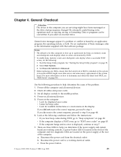
... on page 59. Problem determination tips Due to the variety of the LEDs when the power is OK, replace the power supply. If it failing? - ON OFF Replace the system board ON ON Replace the power supply If the Diagnostic LEDs are considered identical only if they: 44 Hardware Maintenance Manual v Machine... pressed) ON d. v If the test stops and you receive an error, replace the part that can be encountered, use - OFF Make sure the power cord is attached to a working , what changes were made prior to assist you in use the following table. What, when, where, single, or...
... on page 59. Problem determination tips Due to the variety of the LEDs when the power is OK, replace the power supply. If it failing? - ON OFF Replace the system board ON ON Replace the power supply If the Diagnostic LEDs are considered identical only if they: 44 Hardware Maintenance Manual v Machine... pressed) ON d. v If the test stops and you receive an error, replace the part that can be encountered, use - OFF Make sure the power cord is attached to a working , what changes were made prior to assist you in use the following table. What, when, where, single, or...

User Manual
Page 63
...switch for proper installation. Check/Verify Check the following : 1. v Power Cord v On/Off Switch connector v On/Off Switch Power Supply connector v System Board Power Supply connectors v Microprocessor(s) connection Check the power cord for a description of your error symptoms in the first part of...Power Cord Power-on the failing hard disk drive. 2. The drive is listed first. Attempt to -FRU index lists error symptoms and possible causes. No operating system installed on page 43. FRU/Action Check the configuration and ensure the start -up the data on Switch © Lenovo...
...switch for proper installation. Check/Verify Check the following : 1. v Power Cord v On/Off Switch connector v On/Off Switch Power Supply connector v System Board Power Supply connectors v Microprocessor(s) connection Check the power cord for a description of your error symptoms in the first part of...Power Cord Power-on the failing hard disk drive. 2. The drive is listed first. Attempt to -FRU index lists error symptoms and possible causes. No operating system installed on page 43. FRU/Action Check the configuration and ensure the start -up the data on Switch © Lenovo...

User Manual
Page 64
... computer and the two diagnostic LEDs are located on the computer. 3. v Check the power cord for continuity. Power LED ON OFF OFF (after the power button has been pressed) ON 1. Power-on the power supply at a time, until the computer works correctly. 58 Hardware Maintenance Manual OFF Replace the...LEDs and refer to a working correctly. v If the problem persists, replace the power supply. OFF v Make sure the power cord is OK. There are three LEDs to help you determine if the power supply and system board are in the normal condition and the problem persists, replace the ...
... computer and the two diagnostic LEDs are located on the computer. 3. v Check the power cord for continuity. Power LED ON OFF OFF (after the power button has been pressed) ON 1. Power-on the power supply at a time, until the computer works correctly. 58 Hardware Maintenance Manual OFF Replace the...LEDs and refer to a working correctly. v If the problem persists, replace the power supply. OFF v Make sure the power cord is OK. There are three LEDs to help you determine if the power supply and system board are in the normal condition and the problem persists, replace the ...

User Manual
Page 76
... log file 1. Go to review the log file 2. See "Flash update procedures" on page 516 3. Replace component under test PCI card 2. IDE signal cable 2. Check power supply voltages 3. Reseat IDE signal cable 4. IDE device 5. Flash the system. See "Flash update procedures" on page 516 3. Reseat IDE signal cable 4. Check...
... log file 1. Go to review the log file 2. See "Flash update procedures" on page 516 3. Replace component under test PCI card 2. IDE signal cable 2. Check power supply voltages 3. Reseat IDE signal cable 4. IDE device 5. Flash the system. See "Flash update procedures" on page 516 3. Reseat IDE signal cable 4. Check...

User Manual
Page 77
SCSI signal cable 2. System board 1. SCSI device 4. Check power supply 3. SCSI device 4. Re-start the test, if necessary 1. Re-run test 3. Symptom-to reset the log file 1. See Chapter 6, "Using the Setup Utility," on page ... component that is called out is connected and/or enabled. Go to review the log file 2. Press F3 to "Undetermined problems" on page 88 1. Check power supply 3. SCSI adapter card, if installed 5. SCSI device 4. System board Information only Re-start the test to -FRU Index 71 SCSI adapter card, if installed 5. Replace...
SCSI signal cable 2. System board 1. SCSI device 4. Check power supply 3. SCSI device 4. Re-start the test, if necessary 1. Re-run test 3. Symptom-to reset the log file 1. See Chapter 6, "Using the Setup Utility," on page ... component that is called out is connected and/or enabled. Go to review the log file 2. Press F3 to "Undetermined problems" on page 88 1. Check power supply 3. SCSI adapter card, if installed 5. SCSI device 4. System board Information only Re-start the test to -FRU Index 71 SCSI adapter card, if installed 5. Replace...

User Manual
Page 82
...-XXX Voltage Sensor(s) Test aborted by user Information only Re-start the test to "Undetermined problems" on page 53 2. Flash the system and re-test. Power supply 2. Re-run test 3. Voltage Regulator Module (VRM) 2. Make sure the component that is connected and/or enabled. Replace component under test 170-198-XXX Voltage...
...-XXX Voltage Sensor(s) Test aborted by user Information only Re-start the test to "Undetermined problems" on page 53 2. Flash the system and re-test. Power supply 2. Re-run test 3. Voltage Regulator Module (VRM) 2. Make sure the component that is connected and/or enabled. Replace component under test 170-198-XXX Voltage...
User Manual
Page 83
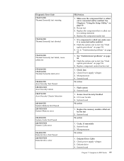
... "Undetermined problems" on page 516 3. Replace the component that is called out is called out in warning statement 4. Replace the component under function test 1. Check Power supply voltages 3. Make sure the component that is connected and/or enabled. Microprocessor 4. System board No action 1. Diagnostic Error Code 175-197-XXX Thermal Sensor(s) test... Passed 206-XXX-XXX Diskette Drive error FRU/Action 1. Re-run test 3. If a component is called out by the test 2. System board No action 1. Check power supply voltages 3. Diskette drive 4.
... "Undetermined problems" on page 516 3. Replace the component that is called out is called out in warning statement 4. Replace the component under function test 1. Check Power supply voltages 3. Make sure the component that is connected and/or enabled. Microprocessor 4. System board No action 1. Diagnostic Error Code 175-197-XXX Thermal Sensor(s) test... Passed 206-XXX-XXX Diskette Drive error FRU/Action 1. Re-run test 3. If a component is called out by the test 2. System board No action 1. Check power supply voltages 3. Diskette drive 4.
User Manual
Page 84
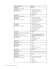
Check power supply voltages 3. Hard Disk drive (SCSI) 5. SCSI adapter card 6. System board No action 1. Check and test mouse 3. Mouse 2. System board 1. Reseat the hard disk drive cable 4. ... test failure FRU/Action No action 1. System board No action Remove the Joystick and re-test the system No action 1. CD-ROM Drive Cable 2. Check power supply voltages 3. Hard Disk Drive Cable 2. Reseat the hard disk drive cable 4. Monitor 4. CD-ROM drive 4. Hard Disk drive (IDE) 5. Check...
Check power supply voltages 3. Hard Disk drive (SCSI) 5. SCSI adapter card 6. System board No action 1. Check and test mouse 3. Mouse 2. System board 1. Reseat the hard disk drive cable 4. ... test failure FRU/Action No action 1. System board No action Remove the Joystick and re-test the system No action 1. CD-ROM Drive Cable 2. Check power supply voltages 3. Hard Disk Drive Cable 2. Reseat the hard disk drive cable 4. Monitor 4. CD-ROM drive 4. Hard Disk drive (IDE) 5. Check...
User Manual
Page 88
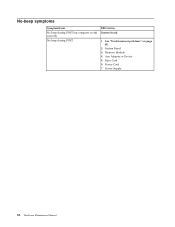
No-beep symptoms Symptom/Error No beep during POST. FRU/Action System board 1. Memory Module 4. Power Supply 82 Hardware Maintenance Manual Riser Card 6. No beep during POST but computer works correctly. See "Undetermined problems" on page 88. 2. Any Adapter or Device 5. System Board 3. Power Cord 7.
No-beep symptoms Symptom/Error No beep during POST. FRU/Action System board 1. Memory Module 4. Power Supply 82 Hardware Maintenance Manual Riser Card 6. No beep during POST but computer works correctly. See "Undetermined problems" on page 88. 2. Any Adapter or Device 5. System Board 3. Power Cord 7.
User Manual
Page 92
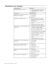
... a Wake on LAN (if applicable) Dead computer. Computer will not RPL from server Computer will not power-off. Incorrect memory size during POST FRU/Action 1. Check power supply and signal cable connections to enable Wake on LAN feature is active. Riser card 1. System Board 86...with an otherwise blank display. Ensure that network adapter is using correct MAC address 5. Riser card 1. Primary Hard Disk Drive 3. See "Power Supply Errors" on page 57. Ensure that the operating system settings are set to network adapter 2. Ensure network administrator is enabled for RPL ...
... a Wake on LAN (if applicable) Dead computer. Computer will not RPL from server Computer will not power-off. Incorrect memory size during POST FRU/Action 1. Check power supply and signal cable connections to enable Wake on LAN feature is active. Riser card 1. System Board 86...with an otherwise blank display. Ensure that network adapter is using correct MAC address 5. Riser card 1. Primary Hard Disk Drive 3. See "Power Supply Errors" on page 57. Ensure that the operating system settings are set to network adapter 2. Ensure network administrator is enabled for RPL ...
User Manual
Page 93
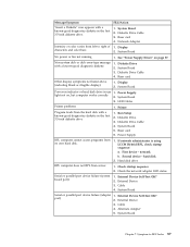
...- System Board Serial or parallel port device failure (adapter port) 1. Symptom-to right of 1. See "Power Supply Errors" on , but computer works correctly 2. System Board 3. Power Supply RPL computer cannot access programs from server 1. If network administrator is using LCCM Hybrid RPL, check startup sequence:... Drive Cable 4. LED Cables Printer problems 1. Hard disk drive RPL computer does not RPL from its own hard disk. 1. Power Supply light not on page 57. External Device Self-Test OK? 2. Network Adapter Intensity or color varies from the hard disk with...
...- System Board Serial or parallel port device failure (adapter port) 1. Symptom-to right of 1. See "Power Supply Errors" on , but computer works correctly 2. System Board 3. Power Supply RPL computer cannot access programs from server 1. If network administrator is using LCCM Hybrid RPL, check startup sequence:... Drive Cable 4. LED Cables Printer problems 1. Hard disk drive RPL computer does not RPL from its own hard disk. 1. Power Supply light not on page 57. External Device Self-Test OK? 2. Network Adapter Intensity or color varies from the hard disk with...
User Manual
Page 94
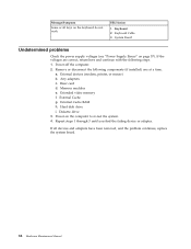
... adapter. If all keys on the keyboard do not work FRU/Action 1. Keyboard 2. Any adapters c. Riser card d. Extended video memory f. Power-on page 57). System Board Undetermined problems Check the power supply voltages (see "Power Supply Errors" on the computer to re-test the system. 4. a. External Cache g. Keyboard Cable 3. Remove or disconnect the following steps...
... adapter. If all keys on the keyboard do not work FRU/Action 1. Keyboard 2. Any adapters c. Riser card d. Extended video memory f. Power-on page 57). System Board Undetermined problems Check the power supply voltages (see "Power Supply Errors" on the computer to re-test the system. 4. a. External Cache g. Keyboard Cable 3. Remove or disconnect the following steps...

User Manual
Page 96
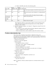
Machine Type 8099 1 2 3 14 13 12 8 9 10 4 5 6 7 11 Item # 8099 FRUs 1 Cover, Kensington Lock (all models EXCEPT J1J J2J J3J J4J K1J K2J K3J K4J) 2 Power Supply (225 Watt) (models CTO B1A B1T B2K B3K B4G 21J 22K 23K 24K 31J 32J 33J 34K D1K E1K F1K A1K B8K BBK BCK D3K ... 2AT 43A 43T 44J D7K D8K D9K DAK G1J G2J G3K G4K G5K G6K G7A G7T 91K 92K 93K 94K 95J 96J 97J 98J 53J) 2 Power Supply (225 Watt) China Version (models CTO B1Q B5S B5P B5Y B6S B6P B6Y B7S B7P B7Y 25S 25P 25Y 35S 35P 35Y D2S D2P D2Y...
Machine Type 8099 1 2 3 14 13 12 8 9 10 4 5 6 7 11 Item # 8099 FRUs 1 Cover, Kensington Lock (all models EXCEPT J1J J2J J3J J4J K1J K2J K3J K4J) 2 Power Supply (225 Watt) (models CTO B1A B1T B2K B3K B4G 21J 22K 23K 24K 31J 32J 33J 34K D1K E1K F1K A1K B8K BBK BCK D3K ... 2AT 43A 43T 44J D7K D8K D9K DAK G1J G2J G3K G4K G5K G6K G7A G7T 91K 92K 93K 94K 95J 96J 97J 98J 53J) 2 Power Supply (225 Watt) China Version (models CTO B1Q B5S B5P B5Y B6S B6P B6Y B7S B7P B7Y 25S 25P 25Y 35S 35P 35Y D2S D2P D2Y...
User Manual
Page 115
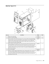
FRU lists 109 Machine Type 8110 3 4 1 2 9 5 13 8 12 10 11 7 6 Item # 8110 FRUs 1 Bezel Asm (all models) 2 Chassis Asm (all models) 3 Power supply, 310 W, standard (models CTO A1J A2J A3J B1A B1T B2K B3K B4K B5K B6G 21K 22K 23K 31J 32J 33J 34K 35K 41K D1K E1K ... K1K K2K A6K A7K BCK BDK BEK BFK 24K 25K D7K D8K D9K DAK DBK G1K G2K G3K G4K G5K 91K 92K 93K 94K 95K) 3 Power supply, 310 W (models CTO-A CTO-L B1Q A2S A2P A2Y B1S B1P B1Y B3S B3P B3Y B4S B4P B4Y B5S B5P B5Y 22S 22P 22Y 32S 32P...
FRU lists 109 Machine Type 8110 3 4 1 2 9 5 13 8 12 10 11 7 6 Item # 8110 FRUs 1 Bezel Asm (all models) 2 Chassis Asm (all models) 3 Power supply, 310 W, standard (models CTO A1J A2J A3J B1A B1T B2K B3K B4K B5K B6G 21K 22K 23K 31J 32J 33J 34K 35K 41K D1K E1K ... K1K K2K A6K A7K BCK BDK BEK BFK 24K 25K D7K D8K D9K DAK DBK G1K G2K G3K G4K G5K 91K 92K 93K 94K 95K) 3 Power supply, 310 W (models CTO-A CTO-L B1Q A2S A2P A2Y B1S B1P B1Y B3S B3P B3Y B4S B4P B4Y B5S B5P B5Y 22S 22P 22Y 32S 32P...


