User Manual
Page 5
... . . 89 Installing or replacing a memory module . . . . 90 Installing or replacing a PCI card 92 Replacing the battery 95 Replacing the power supply assembly . . . . . 96 Replacing the heat sink and fan assembly . . . . 98 Replacing the microprocessor 100 Replacing the system board...replacement 120 Chapter 9. General checkout . . . . . 43 Problem determination tips 43 Chapter 5. General information . . . . 39 Lenovo ThinkVantage Tools 39 Lenovo Care 39 Access Help 39 Additional information resources 40 Specifications 41 For machine types: 7515, 7523, 7569, and 7611.. . 41 For ...
... . . 89 Installing or replacing a memory module . . . . 90 Installing or replacing a PCI card 92 Replacing the battery 95 Replacing the power supply assembly . . . . . 96 Replacing the heat sink and fan assembly . . . . 98 Replacing the microprocessor 100 Replacing the system board...replacement 120 Chapter 9. General checkout . . . . . 43 Problem determination tips 43 Chapter 5. General information . . . . 39 Lenovo ThinkVantage Tools 39 Lenovo Care 39 Access Help 39 Additional information resources 40 Specifications 41 For machine types: 7515, 7523, 7569, and 7611.. . 41 For ...
User Manual
Page 10
...strips and machine frames. Working near you may prevent a current from power, telephone, and communication cables can then operate the switch or unplug the power cord quickly. v Never assume that supplies power to the machine and to work alone under hazardous conditions or near...electrical currents. Many customers have handles covered with a soft material that contain small conductive fibers to switch off controls, is near power supplies - v Do not work on electrical equipment; Ensure that has hazardous voltages. Remember: There must be there to decrease electrostatic ...
...strips and machine frames. Working near you may prevent a current from power, telephone, and communication cables can then operate the switch or unplug the power cord quickly. v Never assume that supplies power to the machine and to work alone under hazardous conditions or near...electrical currents. Many customers have handles covered with a soft material that contain small conductive fibers to switch off controls, is near power supplies - v Do not work on electrical equipment; Ensure that has hazardous voltages. Remember: There must be there to decrease electrostatic ...
User Manual
Page 11
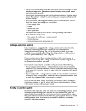
...electrical circuits with the power on the computer. Power supply units - Motor generators and similar units. (This practice ensures correct grounding of these products. Use caution; Voltage-selection switch Some computers are equipped with a voltage-selection switch located near the power-cord connection point on...outlet until you in your computer has a voltage-selection switch, ensure that you are moist floors, nongrounded power extension cables, power surges, and missing safety grounds. Safety inspection guide The intent of a plastic dental mirror. v If your electrical outlet. ...
...electrical circuits with the power on the computer. Power supply units - Motor generators and similar units. (This practice ensures correct grounding of these products. Use caution; Voltage-selection switch Some computers are equipped with a voltage-selection switch located near the power-cord connection point on...outlet until you in your computer has a voltage-selection switch, ensure that you are moist floors, nongrounded power extension cables, power surges, and missing safety grounds. Safety inspection guide The intent of a plastic dental mirror. v If your electrical outlet. ...
User Manual
Page 12
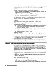
... be considered sensitive to electrostatic discharge (ESD). Consider these conditions and the safety hazards they present: v Electrical hazards, especially primary power (primary voltage on your skin to eliminate static on the frame can occur when there is a difference in a checklist. A ...mat, and the person handling the part are all at the same charge. Power-off , and the power cord disconnected. Checklist: 1. Protect against your body. 6 Hardware Maintenance Manual Check that the power-supply cover fasteners (screws or rivets) have been certified (ISO 9000) as specified ...
... be considered sensitive to electrostatic discharge (ESD). Consider these conditions and the safety hazards they present: v Electrical hazards, especially primary power (primary voltage on your skin to eliminate static on the frame can occur when there is a difference in a checklist. A ...mat, and the person handling the part are all at the same charge. Power-off , and the power cord disconnected. Checklist: 1. Protect against your body. 6 Hardware Maintenance Manual Check that the power-supply cover fasteners (screws or rivets) have been certified (ISO 9000) as specified ...

User Manual
Page 16
CAUTION: The power control button on the device and the power switch on the power supply do not turn off the electrical current supplied to the device. The device also might have more than one power cord. To remove all electrical current from the device, ensure that all power cords are disconnected from the power source. 2 1 10 Hardware Maintenance Manual
CAUTION: The power control button on the device and the power switch on the power supply do not turn off the electrical current supplied to the device. The device also might have more than one power cord. To remove all electrical current from the device, ensure that all power cords are disconnected from the power source. 2 1 10 Hardware Maintenance Manual

User Manual
Page 61
...POST error message, diagnose the POST error message first. 3. Error The start-up the data on Switch © Copyright Lenovo 2009 55 Install an operating system on page 81. Chapter 7. Symptom-to-FRU index The Symptom-to have available when ... If you are unable to correct the problem using this index. v Power Cord v On/Off Switch connector v On/Off Switch Power Supply connector v System Board Power Supply connectors v Microprocessor(s) connection Check the power cord for continuity. No operating system installed on switch for continuity. The ...
...POST error message, diagnose the POST error message first. 3. Error The start-up the data on Switch © Copyright Lenovo 2009 55 Install an operating system on page 81. Chapter 7. Symptom-to-FRU index The Symptom-to have available when ... If you are unable to correct the problem using this index. v Power Cord v On/Off Switch connector v On/Off Switch Power Supply connector v System Board Power Supply connectors v Microprocessor(s) connection Check the power cord for continuity. No operating system installed on switch for continuity. The ...

User Manual
Page 73
... 81 2. Go to "Undetermined problems" on page 51 2. Riser card, if installed 3. IDE device 5. System board No action 1. Press F3 to -FRU index 67 Check power supply voltages 3. System board Information only Re-start the test to "Undetermined problems" on page 51 2. Make sure the component that is called out is connected...
... 81 2. Go to "Undetermined problems" on page 51 2. Riser card, if installed 3. IDE device 5. System board No action 1. Press F3 to -FRU index 67 Check power supply voltages 3. System board Information only Re-start the test to "Undetermined problems" on page 51 2. Make sure the component that is called out is connected...

User Manual
Page 74
... a disc" on page 278 3. Go to reset the log file 1. Go to review the log file 2. Check power supply 3. IDE device 5. Make sure the component that is called out in warning statement 4. Re-run test 3. Check power supply 3. Reseat IDE signal cable 4. See Chapter 6, "Using the Setup Utility program," on page 81 2. Flash the...
... a disc" on page 278 3. Go to reset the log file 1. Go to review the log file 2. Check power supply 3. IDE device 5. Make sure the component that is called out in warning statement 4. Re-run test 3. Check power supply 3. Reseat IDE signal cable 4. See Chapter 6, "Using the Setup Utility program," on page 81 2. Flash the...

User Manual
Page 75
...-XXX RAID interface Failure 035-195-XXX RAID interface Test aborted by user FRU/Action 1. See "Updating (flashing) BIOS from a disc" on page 278 3. Check power supply 3. Flash the system and re-test. See "Updating (flashing) BIOS from a disc" on page 51 2.
...-XXX RAID interface Failure 035-195-XXX RAID interface Test aborted by user FRU/Action 1. See "Updating (flashing) BIOS from a disc" on page 278 3. Check power supply 3. Flash the system and re-test. See "Updating (flashing) BIOS from a disc" on page 51 2.

User Manual
Page 80
Flash the system and re-test. Power supply 2. Re-start the test, if necessary 175-196-XXX Thermal Sensor(s) test halt, error threshold exceeded 1. Make sure the component that is connected and/or ...
Flash the system and re-test. Power supply 2. Re-start the test, if necessary 175-196-XXX Thermal Sensor(s) test halt, error threshold exceeded 1. Make sure the component that is connected and/or ...

User Manual
Page 81
... out, make sure it is connected and/or enabled 2. Check fans 2. C2 Cover Switch 3. Cache, if removable 2. See "Undetermined problems" on page 81 1. Check Power supply voltages 3. Check power supply voltages 3. Assure Asset Security Enabled 2. Diskette Drive Cable 2. Symptom-to "Undetermined problems" on page 81 2. Microprocessor 4. System board No action 1. Diagnostic error code 175...
... out, make sure it is connected and/or enabled 2. Check fans 2. C2 Cover Switch 3. Cache, if removable 2. See "Undetermined problems" on page 81 1. Check Power supply voltages 3. Check power supply voltages 3. Assure Asset Security Enabled 2. Diskette Drive Cable 2. Symptom-to "Undetermined problems" on page 81 2. Microprocessor 4. System board No action 1. Diagnostic error code 175...

User Manual
Page 82
... 3. SCSI adapter card 6. Mouse 2. Run Setup to enable DDC 2. Cable 3. System board No action 76 Hardware Maintenance Manual Check power supply voltages 3. Hard Disk Drive Cable 2. Check power supply voltages 3. Hard Disk Drive Cable 2. System board No action 1. Monitor 4. CD-ROM Drive Cable 2. System board No action 1. System board 1. CD-ROM drive 4. System board...
... 3. SCSI adapter card 6. Mouse 2. Run Setup to enable DDC 2. Cable 3. System board No action 76 Hardware Maintenance Manual Check power supply voltages 3. Hard Disk Drive Cable 2. Check power supply voltages 3. Hard Disk Drive Cable 2. System board No action 1. Monitor 4. CD-ROM Drive Cable 2. System board No action 1. System board 1. CD-ROM drive 4. System board...
User Manual
Page 86
... 2. Video adapter (if present) 3. Intensity or color varies from server Computer will not perform a Wake on page 51) 4. Power Switch 2. Power Supply 2. Flashing cursor with a known-good diagnostics diskette in startup sequence as first device or first device after diskette 2. Ensure Wake on... administrator of new MAC address) 1. Ensure no interrupt or I/O address conflicts 6. Computer will not power-off. System Board 3. System Board 2. Run the Memory tests 2. See "Power supply problems" on LAN 3. Ensure that network adapter is using correct MAC address 5. Ensure that the ...
... 2. Video adapter (if present) 3. Intensity or color varies from server Computer will not perform a Wake on page 51) 4. Power Switch 2. Power Supply 2. Flashing cursor with a known-good diagnostics diskette in startup sequence as first device or first device after diskette 2. Ensure Wake on... administrator of new MAC address) 1. Ensure no interrupt or I/O address conflicts 6. Computer will not power-off. System Board 3. System Board 2. Run the Memory tests 2. See "Power supply problems" on LAN 3. Ensure that network adapter is using correct MAC address 5. Ensure that the ...
User Manual
Page 87
Diskette Drive 2. System Board Printer problems 1. Power Supply RPL computer cannot access programs from server 1. Second device - Cable 4. a. System Board 5. Hard disk drive RPL computer does not RPL from its own hard disk. 1. ... and the optical drive is using LCCM Hybrid RPL, check startup sequence: a. hard disk 2. External Device Self-Test OK? 2. Any adapters Chapter 7. Alternate Adapter 5. Keyboard 2. Power switch/LED assembly light not on the keyboard do not work 1. External Device Self-Test OK? 2. System Board Some or all keys on , but computer...
Diskette Drive 2. System Board Printer problems 1. Power Supply RPL computer cannot access programs from server 1. Second device - Cable 4. a. System Board 5. Hard disk drive RPL computer does not RPL from its own hard disk. 1. ... and the optical drive is using LCCM Hybrid RPL, check startup sequence: a. hard disk 2. External Device Self-Test OK? 2. Any adapters Chapter 7. Alternate Adapter 5. Keyboard 2. Power switch/LED assembly light not on the keyboard do not work 1. External Device Self-Test OK? 2. System Board Some or all keys on , but computer...

User Manual
Page 94
Figure 4. Figure 4 shows the locations of the various components in your computer. Locating components To remove the computer cover, see "Removing the computer cover" on page 86. Component locations 1 Heat sink and fan assembly 2 Memory modules 3 Battery 4 PCI Express x16 graphics card slot 5 PCI card 6 PCI card slot 7 PCI Express x1 card slot 8 Cover presence switch (Intrusion switch) (some models) 9 Rear fan assembly 10 Power supply assembly 88 Hardware Maintenance Manual
Figure 4. Figure 4 shows the locations of the various components in your computer. Locating components To remove the computer cover, see "Removing the computer cover" on page 86. Component locations 1 Heat sink and fan assembly 2 Memory modules 3 Battery 4 PCI Express x16 graphics card slot 5 PCI card 6 PCI card slot 7 PCI Express x1 card slot 8 Cover presence switch (Intrusion switch) (some models) 9 Rear fan assembly 10 Power supply assembly 88 Hardware Maintenance Manual
User Manual
Page 102
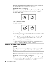
...and all drives. Replacing the power supply assembly Attention Do not open your computer. See "Removing the computer cover" on how to set the date, time, and any repair before reading and understanding the "Important safety information" in the ThinkCentre Safety and Warranty Guide for...and disposing of the ThinkCentre Safety and Warranty Guide, go to: http://www.lenovo.com/support This section provides instructions on page 86. 2. Use the Setup Utility program to replace the power supply assembly. Refer to the "Lithium battery notice" in the ThinkCentre Safety and Warranty ...
...and all drives. Replacing the power supply assembly Attention Do not open your computer. See "Removing the computer cover" on how to set the date, time, and any repair before reading and understanding the "Important safety information" in the ThinkCentre Safety and Warranty Guide for...and disposing of the ThinkCentre Safety and Warranty Guide, go to: http://www.lenovo.com/support This section provides instructions on page 86. 2. Use the Setup Utility program to replace the power supply assembly. Refer to the "Lithium battery notice" in the ThinkCentre Safety and Warranty ...
User Manual
Page 103
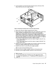
... correct replacement. Note: Use only screws provided by Lenovo. 8. Replacing FRUs - v If the voltage supply range in the chassis. 7. Install the four screws to the system board. 9. Chapter 8. Remove the old power supply assembly from the chassis. 5. Install the new power supply assembly into the chassis so that the power supply assembly is 100-127 V AC, set the...
... correct replacement. Note: Use only screws provided by Lenovo. 8. Replacing FRUs - v If the voltage supply range in the chassis. 7. Install the four screws to the system board. 9. Chapter 8. Remove the old power supply assembly from the chassis. 5. Install the new power supply assembly into the chassis so that the power supply assembly is 100-127 V AC, set the...

User Manual
Page 134
Figure 43. Figure 43 shows the location of the various components in your computer. Component locations 1 Hard disk drive 2 Heat sink and fan assembly 3 Internal speaker 4 Optical drive 5 Memory slots 6 Power supply assembly 128 Hardware Maintenance Manual Locating components To open the computer cover, see "Opening the computer cover" on page 126.
Figure 43. Figure 43 shows the location of the various components in your computer. Component locations 1 Hard disk drive 2 Heat sink and fan assembly 3 Internal speaker 4 Optical drive 5 Memory slots 6 Power supply assembly 128 Hardware Maintenance Manual Locating components To open the computer cover, see "Opening the computer cover" on page 126.

User Manual
Page 146
..." on page 126. 3. To replace the power supply assembly: 1. Remove the four screws at the rear of the ThinkCentre Safety and Warranty Guide, go to: http://www.lenovo.com/support This section provides instructions on how to the power supply assembly. 4. Removing the retaining screws for the power supply assembly 2. Replacing the power supply assembly Attention Do not open your...
..." on page 126. 3. To replace the power supply assembly: 1. Remove the four screws at the rear of the ThinkCentre Safety and Warranty Guide, go to: http://www.lenovo.com/support This section provides instructions on how to the power supply assembly. 4. Removing the retaining screws for the power supply assembly 2. Replacing the power supply assembly Attention Do not open your...

User Manual
Page 147
See "Replacing the hard disk drive" on the system board 6. Remove the power supply assembly cables from the power connectors 1 and 2 . Replacing FRUs - 607 141 Disconnect the power supply assembly cables from all drives and from the cable clips and ties. 7. Note: You might need to remove the hard disk drive to gain easy access to the power connector 1 . Removing the power supply assembly Chapter 9. Figure 59. Figure 58. Power connectors on page 136. Slide the power supply assembly away from the chassis and remove it from the computer. 5.
See "Replacing the hard disk drive" on the system board 6. Remove the power supply assembly cables from the power connectors 1 and 2 . Replacing FRUs - 607 141 Disconnect the power supply assembly cables from all drives and from the cable clips and ties. 7. Note: You might need to remove the hard disk drive to gain easy access to the power connector 1 . Removing the power supply assembly Chapter 9. Figure 59. Figure 58. Power connectors on page 136. Slide the power supply assembly away from the chassis and remove it from the computer. 5.


