Hardware Maintenance Manual
Page 5
... program . . . . . 55 Using passwords 55 Password considerations 56 User Password 56 Administrator Password 56 IDE Drive User Password 56 IDE Drive Master Password 56 © Lenovo 2005, 2008. hard drive 53 Viewing the test log 54 Chapter 6. Setting, changing, and deleting a password . . . 57 Using Security Profile by Device 57 Selecting...the hard disk drive . . . 109 Removing and replacing the optical drive . . . . 110 Removing and replacing the diskette drive . . . 111 Removing and replacing the fan assembly . . . . 112 Closing the cover and connecting cables . . . . 113 Chapter 9.
... program . . . . . 55 Using passwords 55 Password considerations 56 User Password 56 Administrator Password 56 IDE Drive User Password 56 IDE Drive Master Password 56 © Lenovo 2005, 2008. hard drive 53 Viewing the test log 54 Chapter 6. Setting, changing, and deleting a password . . . 57 Using Security Profile by Device 57 Selecting...the hard disk drive . . . 109 Removing and replacing the optical drive . . . . 110 Removing and replacing the diskette drive . . . 111 Removing and replacing the fan assembly . . . . 112 Closing the cover and connecting cables . . . . 113 Chapter 9.
Hardware Maintenance Manual
Page 6
Removing and replacing the diskette drive . . . 133 Removing and replacing the fan assembly . . . . 134 Replacing the cover and connecting the cables . . 135 Chapter 10. FRU lists 161 Machine Type 8095 161 Machine Type 8098 167 Machine ...and replacing the hard disk drive . . . 152 Removing and replacing the optical drive . . . . 153 Removing and replacing the diskette drive . . . 154 Removing and replacing the fan assembly . . . . 154 Removing and replacing the internal speaker . . . 157 Removing and replacing the power button and LED assembly 157 Closing the cover and connecting cables...
Removing and replacing the diskette drive . . . 133 Removing and replacing the fan assembly . . . . 134 Replacing the cover and connecting the cables . . 135 Chapter 10. FRU lists 161 Machine Type 8095 161 Machine Type 8098 167 Machine ...and replacing the hard disk drive . . . 152 Removing and replacing the optical drive . . . . 153 Removing and replacing the diskette drive . . . 154 Removing and replacing the fan assembly . . . . 154 Removing and replacing the internal speaker . . . 157 Removing and replacing the power button and LED assembly 157 Closing the cover and connecting cables...

Hardware Maintenance Manual
Page 13
... safety items installed to assist you can continue without first correcting the problem. Power-off power. - Disconnect the power cord. 3. Remove the cover. Blowers and fans - Each machine, as loose or missing hardware The guide consists of a series of features or options not covered by this inspection guide is conductive; If...
... safety items installed to assist you can continue without first correcting the problem. Power-off power. - Disconnect the power cord. 3. Remove the cover. Blowers and fans - Each machine, as loose or missing hardware The guide consists of a series of features or options not covered by this inspection guide is conductive; If...

Hardware Maintenance Manual
Page 50
.... Actual sound-pressure levels in a given location might be different from the stated values depending on the number of fans and the speed of the fans. Maximum configuration: 548.8 Btu/hr (160 watts) 44 Hardware Maintenance Manual Average sound-pressure levels for computers with ...thermal units (Btu) per hour: Minimum configuration: 205.8 Btu/hr (60 watts) Acoustical noise-emission values Note: In this computer, fan speed is controlled by the American National Standards Institute (ANSI) S12.10 and ISO 7779 and are reported in controlled acoustical environments according ...
.... Actual sound-pressure levels in a given location might be different from the stated values depending on the number of fans and the speed of the fans. Maximum configuration: 548.8 Btu/hr (160 watts) 44 Hardware Maintenance Manual Average sound-pressure levels for computers with ...thermal units (Btu) per hour: Minimum configuration: 205.8 Btu/hr (60 watts) Acoustical noise-emission values Note: In this computer, fan speed is controlled by the American National Standards Institute (ANSI) S12.10 and ISO 7779 and are reported in controlled acoustical environments according ...
Hardware Maintenance Manual
Page 85
... 2. See "Flash update procedures" on page 90 2. Flash the system and re-test. Flash system 2. Replace the memory module called out in warning statement 4. Check fans 2. System board No action 1. Make sure the component that is connected and/or enabled 2. See "Undetermined problems" on page 338 3. Replace component under test 1. System...
... 2. See "Flash update procedures" on page 90 2. Flash the system and re-test. Flash system 2. Replace the memory module called out in warning statement 4. Check fans 2. System board No action 1. Make sure the component that is connected and/or enabled 2. See "Undetermined problems" on page 338 3. Replace component under test 1. System...
Hardware Maintenance Manual
Page 95
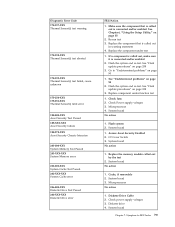
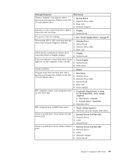
... blank or illegible display) 1. Power Supply light not on page 59. Diskette Drive 3. Alternate Adapter 5. Diskette Drive Cable 3. Riser card 4. System Board No power or fan not running 1. Diskette Drive 2. Run Setup 2. Riser card 6. Power Supply RPL computer cannot access programs from server 1. First device - External Device 3. Cable 4. Cable 4. Message/Symptom...
... blank or illegible display) 1. Power Supply light not on page 59. Diskette Drive 3. Alternate Adapter 5. Diskette Drive Cable 3. Riser card 4. System Board No power or fan not running 1. Diskette Drive 2. Run Setup 2. Riser card 6. Power Supply RPL computer cannot access programs from server 1. First device - External Device 3. Cable 4. Cable 4. Message/Symptom...
Hardware Maintenance Manual
Page 100
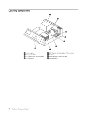
Locating components * XXXXXXXXX* * XXXXXXXXX* 1 Power supply 2 Memory modules 3 PCI Express (x1) PCI connector 4 PCI connector 5 PCI Express (x16) graphics PCI connector 6 Battery 7 Microprocessor and heat sink 8 Fan assembly 94 Hardware Maintenance Manual
Locating components * XXXXXXXXX* * XXXXXXXXX* 1 Power supply 2 Memory modules 3 PCI Express (x1) PCI connector 4 PCI connector 5 PCI Express (x16) graphics PCI connector 6 Battery 7 Microprocessor and heat sink 8 Fan assembly 94 Hardware Maintenance Manual
Hardware Maintenance Manual
Page 101
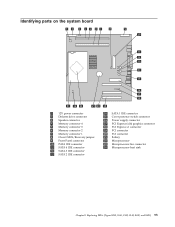
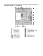
... supply connector 17 PCI Express (x16) graphics connector 18 PCI Express x1 connector 19 PCI connector 20 PCI connector 21 Battery 22 Microprocessor 23 Microprocessor fan connector 24 Microprocessor heat sink Chapter 8. Replacing FRUs (Types 8095, 8141, 8142, 8145, 8420, and 8421) 95
... supply connector 17 PCI Express (x16) graphics connector 18 PCI Express x1 connector 19 PCI connector 20 PCI connector 21 Battery 22 Microprocessor 23 Microprocessor fan connector 24 Microprocessor heat sink Chapter 8. Replacing FRUs (Types 8095, 8141, 8142, 8145, 8420, and 8421) 95
Hardware Maintenance Manual
Page 118
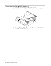
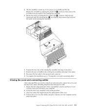
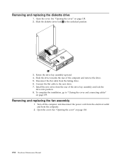
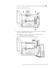
See "Removing the cover" on page 95. 112 Hardware Maintenance Manual See "Identifying parts on the system board" on page 92. 2. Remove the cover. Disconnect the fan cable from the system board fan connector. Removing and replacing the fan assembly 1. Rotate the drive bay assembly upward to gain access to the fan baffle and fan assembly. * XXXXXXXXX* * XXXXXXXXX* 3.
See "Removing the cover" on page 95. 112 Hardware Maintenance Manual See "Identifying parts on the system board" on page 92. 2. Remove the cover. Disconnect the fan cable from the system board fan connector. Removing and replacing the fan assembly 1. Rotate the drive bay assembly upward to gain access to the fan baffle and fan assembly. * XXXXXXXXX* * XXXXXXXXX* 3.
Hardware Maintenance Manual
Page 119
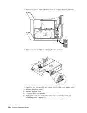
... by pressing the two plastic tabs 3 as shown, then remove the air baffle from the inside of the rotating bay assembly. 5. Slide the fan downward until it down over the computer until the retaining tabs 2 are left inside of the rotating bay assembly. 6. Closing the cover and connecting... position. 3. Ensure that all components have been reassembled correctly and that might impede the replacement of two pieces, an air baffle and the fan. Position the cover over the chassis and pivot it snaps into place. Position the new air baffle in the rotating bay assembly and snap ...
... by pressing the two plastic tabs 3 as shown, then remove the air baffle from the inside of the rotating bay assembly. 5. Slide the fan downward until it down over the computer until the retaining tabs 2 are left inside of the rotating bay assembly. 6. Closing the cover and connecting... position. 3. Ensure that all components have been reassembled correctly and that might impede the replacement of two pieces, an air baffle and the fan. Position the cover over the chassis and pivot it snaps into place. Position the new air baffle in the rotating bay assembly and snap ...
Hardware Maintenance Manual
Page 124
... supply connector 17 PCI Express (x16) graphics connector 18 PCI Express x1 connector 19 PCI connector 20 PCI connector 21 Battery 22 Microprocessor 23 Microprocessor fan connector 24 Microprocessor heat sink 118 Hardware Maintenance Manual
... supply connector 17 PCI Express (x16) graphics connector 18 PCI Express x1 connector 19 PCI connector 20 PCI connector 21 Battery 22 Microprocessor 23 Microprocessor fan connector 24 Microprocessor heat sink 118 Hardware Maintenance Manual

Hardware Maintenance Manual
Page 140
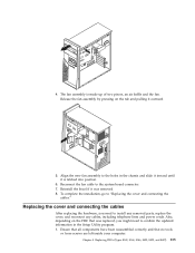
...the cover. See "Removing the cover" on page 118. 3. Disconnect the fan cable from the front of the drive and removing it on the blue retainer... the side of the computer. 4. See "Identifying parts on the system board" on page 116. 2. Removing and replacing the fan assembly 1. Release the diskette disk drive by pressing on the new drive. 5. To complete the installation, go to the drive.... into position. 6. It is not necessary to remove the front bezel to replace the fan assembly. 3. Remove the retainer bracket form the failing drive and install it from the system board...
...the cover. See "Removing the cover" on page 118. 3. Disconnect the fan cable from the front of the drive and removing it on the blue retainer... the side of the computer. 4. See "Identifying parts on the system board" on page 116. 2. Removing and replacing the fan assembly 1. Release the diskette disk drive by pressing on the new drive. 5. To complete the installation, go to the drive.... into position. 6. It is not necessary to remove the front bezel to replace the fan assembly. 3. Remove the retainer bracket form the failing drive and install it from the system board...
Hardware Maintenance Manual
Page 141
...cords. Replacing FRUs (Types 8143, 8144, 8146, 8422, 8423, and 8427) 135 Align the new fan assembly to the holes in the Setup Utility program. 1. Chapter 9. Release the fan assembly by pressing on the FRU that no tools or loose screws are left inside your computer. To ...complete the installation, go to the system board connector. 7. 4. The fan assembly is latched into position. 6. Replacing the cover and connecting the cables After replacing the hardware, you might need to confirm the updated information...
...cords. Replacing FRUs (Types 8143, 8144, 8146, 8422, 8423, and 8427) 135 Align the new fan assembly to the holes in the Setup Utility program. 1. Chapter 9. Release the fan assembly by pressing on the FRU that no tools or loose screws are left inside your computer. To ...complete the installation, go to the system board connector. 7. 4. The fan assembly is latched into position. 6. Replacing the cover and connecting the cables After replacing the hardware, you might need to confirm the updated information...
Hardware Maintenance Manual
Page 146
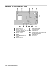
Identifying parts on the system board 1 Fan connectors (2) 8 Diskette drive connector 2 Memory connectors (2) 9 Front panel connector 3 SATA 1 IDE and SATA 2 IDE hard 10 Power connector disk drive connectors (2) 4 PCI riser connector 11 PATA Primary IDE connector (hard disk drive and CD-ROM drive) 5 Battery 12 Power connector 6 Clear CMOS/BIOS recovery 13 Microprocessor jumper 7 Speaker connector 140 Hardware Maintenance Manual
Identifying parts on the system board 1 Fan connectors (2) 8 Diskette drive connector 2 Memory connectors (2) 9 Front panel connector 3 SATA 1 IDE and SATA 2 IDE hard 10 Power connector disk drive connectors (2) 4 PCI riser connector 11 PATA Primary IDE connector (hard disk drive and CD-ROM drive) 5 Battery 12 Power connector 6 Clear CMOS/BIOS recovery 13 Microprocessor jumper 7 Speaker connector 140 Hardware Maintenance Manual
Hardware Maintenance Manual
Page 160
... towards the rear of the drive bay assembly and lock the drive into position. 8. Install the new drive from the computer. 2. Removing and replacing the fan assembly 1. See "Opening the cover" on page 138. 2. Disconnect the flat cable from the failing drive. 6. Connect the flat cable to the unlocked position. 3. Removing...
... towards the rear of the drive bay assembly and lock the drive into position. 8. Install the new drive from the computer. 2. Removing and replacing the fan assembly 1. See "Opening the cover" on page 138. 2. Disconnect the flat cable from the failing drive. 6. Connect the flat cable to the unlocked position. 3. Removing...
Hardware Maintenance Manual
Page 161
Note: Make sure you note the location of the fan cable(s) when you disconnect it from the system board. See "Identifying parts on the system board" on page 140. Chapter 10. Rotate the drive bay assembly upward to gain access to the fan assembly 3 . Disconnect fan assembly cable(s) from the system board. 5. 3. Replacing FRUs (Types 8098, 8171, 8172, 8173, 8424, and 8425) 155 Note: Some models have two fans. 4. Remove the front bezel by releasing the tab as shown.
Note: Make sure you note the location of the fan cable(s) when you disconnect it from the system board. See "Identifying parts on the system board" on page 140. Chapter 10. Rotate the drive bay assembly upward to gain access to the fan assembly 3 . Disconnect fan assembly cable(s) from the system board. 5. 3. Replacing FRUs (Types 8098, 8171, 8172, 8173, 8424, and 8425) 155 Note: Some models have two fans. 4. Remove the front bezel by releasing the tab as shown.
Hardware Maintenance Manual
Page 162
Install the new fan assembly and connect the fan cable to the system board. 9. Lower the drive bay assembly. 12. Replace the cover, and connect the cables. Reinstall the plastic insert. 10. Remove the plastic insert behind the bezel by releasing the tabs as shown: 7. Reinstall the front bezel. 11. See "Closing the cover and connecting cables" on page 159. 156 Hardware Maintenance Manual Remove the fan assembly by releasing the tabs as shown. 8. 6.
Install the new fan assembly and connect the fan cable to the system board. 9. Lower the drive bay assembly. 12. Replace the cover, and connect the cables. Reinstall the plastic insert. 10. Remove the plastic insert behind the bezel by releasing the tabs as shown: 7. Reinstall the front bezel. 11. See "Closing the cover and connecting cables" on page 159. 156 Hardware Maintenance Manual Remove the fan assembly by releasing the tabs as shown. 8. 6.

Hardware Maintenance Manual
Page 170
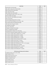
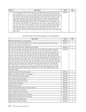
... Compliant) (all models) C2 Cable Asm (models CTO-U CTO-G) Cable, Second Serial Port (all models) Retention module assembly - (all models) Device Retaining Clips (all models) Fan and Duct Asm (all models) System board shield (all models) Cable, SATA (all models) Bezel Kit (all models) Cable and Front USB/Audio Card (all...
... Compliant) (all models) C2 Cable Asm (models CTO-U CTO-G) Cable, Second Serial Port (all models) Retention module assembly - (all models) Device Retaining Clips (all models) Fan and Duct Asm (all models) System board shield (all models) Cable, SATA (all models) Bezel Kit (all models) Cable and Front USB/Audio Card (all...
Hardware Maintenance Manual
Page 176
... Bracket 5.25 to 3.5-inch Mouse, optical wheel (models CTO-U CTO-G 11M) Korean label (models 31K 41K 38K 45K 53K) Cable, Zip Drive 2 drop (all models) Fan assembly (all models) Planar tray, (all models) Kensington Lock Spacer (all models) Planar I/O Shield Kit (all models) Heat Sink Retention Module Asm (all models) PCI...
... Bracket 5.25 to 3.5-inch Mouse, optical wheel (models CTO-U CTO-G 11M) Korean label (models 31K 41K 38K 45K 53K) Cable, Zip Drive 2 drop (all models) Fan assembly (all models) Planar tray, (all models) Kensington Lock Spacer (all models) Planar I/O Shield Kit (all models) Heat Sink Retention Module Asm (all models) PCI...
Hardware Maintenance Manual
Page 186
... DCU DDU DDF DDS DDP DEU DEA DEQ DET) Cable, Second Serial Port (all models) Retention module assembly - (all models) Device Retaining Clips (all models) Fan and Duct Asm (all models) System board shield (all models) Cable, SATA (all models) Bezel Kit (all models) Cable and Front USB/Audio Card (all...
... DCU DDU DDF DDS DDP DEU DEA DEQ DET) Cable, Second Serial Port (all models) Retention module assembly - (all models) Device Retaining Clips (all models) Fan and Duct Asm (all models) System board shield (all models) Cable, SATA (all models) Bezel Kit (all models) Cable and Front USB/Audio Card (all...


