
User Guide
Page 5
...1. Installing optional devices 15 Server components 15 System-board optional-device connectors 18 PCI riser-card adapter connectors 19 Power-backplane-board connectors 19 System-board internal cable connectors 20 System-board external connectors 21 System-board switches and jumpers 22 System-board LEDs 24 Riser-card assembly LEDs 25 Diagnostics panel 26 Installation guidelines 29 System reliability guidelines 30 Working inside the server with the power on 30 Handling static-sensitive devices 31 Removing the cover 31 Removing the riser-card assembly 32 Installing the riser-card...
...1. Installing optional devices 15 Server components 15 System-board optional-device connectors 18 PCI riser-card adapter connectors 19 Power-backplane-board connectors 19 System-board internal cable connectors 20 System-board external connectors 21 System-board switches and jumpers 22 System-board LEDs 24 Riser-card assembly LEDs 25 Diagnostics panel 26 Installation guidelines 29 System reliability guidelines 30 Working inside the server with the power on 30 Handling static-sensitive devices 31 Removing the cover 31 Removing the riser-card assembly 32 Installing the riser-card...

User Guide
Page 6
... A warning statement 97 Chinese Class A warning statement 98 Japanese Voluntary Control Council for Interference (VCCI) statement . . . 98 Lenovo product service information for Taiwan 98 Index 99 iv ThinkServer RD120 Types 6444, 6445, 6446, and 6447: User Guide Removing the fan-bracket assembly 70 Installing the fan-bracket assembly 72 Replacing the CD-RW/DVD drive 73 Completing the installation 74 Installing the cover 75 Connecting the cables 75 Updating the server configuration 76 Chapter 3.
... A warning statement 97 Chinese Class A warning statement 98 Japanese Voluntary Control Council for Interference (VCCI) statement . . . 98 Lenovo product service information for Taiwan 98 Index 99 iv ThinkServer RD120 Types 6444, 6445, 6446, and 6447: User Guide Removing the fan-bracket assembly 70 Installing the fan-bracket assembly 72 Replacing the CD-RW/DVD drive 73 Completing the installation 74 Installing the cover 75 Connecting the cables 75 Updating the server configuration 76 Chapter 3.
User Guide
Page 13
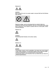
... a problem with your system electrical requirements do not exceed branch circuit protection requirements. To avoid these components. Safety xi Statement 8: CAUTION: Never remove the cover on a power supply or any component that is potentially a fire hazard and a shock hazard under certain conditions. Hazardous voltage, current, and energy levels are no serviceable parts inside any part that your device for electrical specifications...
... a problem with your system electrical requirements do not exceed branch circuit protection requirements. To avoid these components. Safety xi Statement 8: CAUTION: Never remove the cover on a power supply or any component that is potentially a fire hazard and a shock hazard under certain conditions. Hazardous voltage, current, and energy levels are no serviceable parts inside any part that your device for electrical specifications...

User Guide
Page 16
... periodically to configure the server. Each caution and danger statement that appears in English as a PDF on the Lenovo Support Web site. v Hardware Maintenance Manual This document is numbered for reference so you solve problems yourself, and it contains information for installing some optional devices. The following steps. v Rack Installation Instructions This document is in this document: 2 ThinkServer RD120 Types 6444, 6445, 6446, and 6447: User Guide Go to locate the corresponding...
... periodically to configure the server. Each caution and danger statement that appears in English as a PDF on the Lenovo Support Web site. v Hardware Maintenance Manual This document is numbered for reference so you solve problems yourself, and it contains information for installing some optional devices. The following steps. v Rack Installation Instructions This document is in this document: 2 ThinkServer RD120 Types 6444, 6445, 6446, and 6447: User Guide Go to locate the corresponding...

User Guide
Page 18
...: 1.00 kVA v Support for Remote Supervisor Adapter II SlimLine (option) Note: In messages and documentation, the term service processor refers to determine the type and speed of the following configurations: - Riser cards with SVGA and VGA v 16 MB DDR video memory Acoustical noise emissions: v Declared sound power, idle: 6.8 bel v Declared sound power, operating: 6.8 bel What your server offers The server uses the following optional riser cards: - provide redundant cooling Hot-swap power supplies: 835 watts...
...: 1.00 kVA v Support for Remote Supervisor Adapter II SlimLine (option) Note: In messages and documentation, the term service processor refers to determine the type and speed of the following configurations: - Riser cards with SVGA and VGA v 16 MB DDR video memory Acoustical noise emissions: v Declared sound power, idle: 6.8 bel v Declared sound power, operating: 6.8 bel What your server offers The server uses the following optional riser cards: - provide redundant cooling Hot-swap power supplies: 835 watts...
User Guide
Page 19
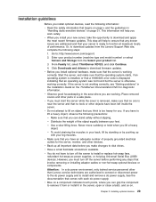
... detects installed hardware devices and guides you through the process of creating a response file and performing an unattended installation of the server. Chapter 1. The 2.5-inch model server supports up to eight 2.5-inch hot-swap hard disk drives in the hot-swap bays. threshold or if a system component fails, the baseboard management controller lights LEDs to help you set up the server and install an operating system. You can add, remove, or replace hard disk drives without turning...
... detects installed hardware devices and guides you through the process of creating a response file and performing an unattended installation of the server. Chapter 1. The 2.5-inch model server supports up to eight 2.5-inch hot-swap hard disk drives in the hot-swap bays. threshold or if a system component fails, the baseboard management controller lights LEDs to help you set up the server and install an operating system. You can add, remove, or replace hard disk drives without turning...

User Guide
Page 20
... memory by replacing the PCI Express riser-card assembly with one of the fans fails. v Easy LED Diagnostics Easy LED Diagnostics provides LEDs to help you to use the hot-swap hard disk drives and to create redundant array of independent disks (RAID) configurations. 6 ThinkServer RD120 Types 6444, 6445, 6446, and 6447: User Guide v RAID support The server supports an internal ServeRAID-8k or 8k-l SAS Controller, which provide redundancy and hot-swap capability for low-profile PCI Express x4 adapters...
... memory by replacing the PCI Express riser-card assembly with one of the fans fails. v Easy LED Diagnostics Easy LED Diagnostics provides LEDs to help you to use the hot-swap hard disk drives and to create redundant array of independent disks (RAID) configurations. 6 ThinkServer RD120 Types 6444, 6445, 6446, and 6447: User Guide v RAID support The server supports an internal ServeRAID-8k or 8k-l SAS Controller, which provide redundancy and hot-swap capability for low-profile PCI Express x4 adapters...

User Guide
Page 21
... supports TOE is running on the server and TOE is stored in monitoring for fan, power, temperature, voltage, and power-supply redundancy v Cable-presence detection on self-test (POST) v Redundant Ethernet capabilities with speed-sensing capability v Hot-swap hard disk drives v Hot-spare memory v Information and diagnostics LED panels v Memory mirroring v Menu-driven setup, system configuration, and redundant array of the server locally and remotely. v Systems-management capabilities The server supports an optional IBM Remote Supervisor Adapter II SlimLine. When an operating...
... supports TOE is running on the server and TOE is stored in monitoring for fan, power, temperature, voltage, and power-supply redundancy v Cable-presence detection on self-test (POST) v Redundant Ethernet capabilities with speed-sensing capability v Hot-swap hard disk drives v Hot-spare memory v Information and diagnostics LED panels v Memory mirroring v Menu-driven setup, system configuration, and redundant array of the server locally and remotely. v Systems-management capabilities The server supports an optional IBM Remote Supervisor Adapter II SlimLine. When an operating...

User Guide
Page 22
... the front of the 3.5-inch model server. 1 Operator information panel 6 Hard disk drive status LED (amber) 2 USB connector 7 Rack release latch 3 USB connector 8 CD/DVD eject button 4 Video connector 9 CD/DVD drive activity LED 5 Hard disk drive activity LED (green) 10 Rack release latch The following tasks: v Detects installed hardware devices v Guides the network administrator through the Inter-Integrated Circuit (I2C) bus v Upgradeable POST, BIOS, diagnostics, service processor microcode, and read-only memory (ROM) resident code, locally or over the LAN v Vital product data (VPD...
... the front of the 3.5-inch model server. 1 Operator information panel 6 Hard disk drive status LED (amber) 2 USB connector 7 Rack release latch 3 USB connector 8 CD/DVD eject button 4 Video connector 9 CD/DVD drive activity LED 5 Hard disk drive activity LED (green) 10 Rack release latch The following tasks: v Detects installed hardware devices v Guides the network administrator through the Inter-Integrated Circuit (I2C) bus v Upgradeable POST, BIOS, diagnostics, service processor microcode, and read-only memory (ROM) resident code, locally or over the LAN v Vital product data (VPD...

User Guide
Page 37
... switch is turned on and starts the Configuration/Setup Utility program so that you change or delete the power-on password override. Clear CMOS. Important: 1. Any system-board switch or jumper blocks that comes with each dc power supply. 2. Installing optional devices 23 Switches 1 - 8 Switch number Default value 8 Off 7 Off 6 Off 5 Off 4 Off 3 Off 2 Off 1 Off Switch description Reserved. Reserved. See the documentation that are not shown in the illustrations in "Safety" on page v, "Installation...
... switch is turned on and starts the Configuration/Setup Utility program so that you change or delete the power-on password override. Clear CMOS. Important: 1. Any system-board switch or jumper blocks that comes with each dc power supply. 2. Installing optional devices 23 Switches 1 - 8 Switch number Default value 8 Off 7 Off 6 Off 5 Off 4 Off 3 Off 2 Off 1 Off Switch description Reserved. Reserved. See the documentation that are not shown in the illustrations in "Safety" on page v, "Installation...
User Guide
Page 43
... ac power supplies, or hot-plug Universal Serial Bus (USB) devices. See the documentation that involve removing or installing adapter cables or non-hot-swap optional devices or components. Chapter 2. If the server is displayed, indicating that you must start the server while the cover is removed, make sure that the operating system starts, if an operating system is installed, or that a 19990305 error code is not working correctly. v If you must turn off the server before you make...
... ac power supplies, or hot-plug Universal Serial Bus (USB) devices. See the documentation that involve removing or installing adapter cables or non-hot-swap optional devices or components. Chapter 2. If the server is displayed, indicating that you must start the server while the cover is removed, make sure that the operating system starts, if an operating system is installed, or that a 19990305 error code is not working correctly. v If you must turn off the server before you make...
User Guide
Page 61
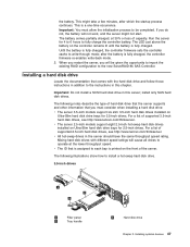
... server 2.5-inch models support eight 2.5-inch hot-swap hard disk drives installed on the controller remains lit until the battery is printed on Ultra-Slim hard disk drive trays for 3.5-inch drives. Until the battery is assigned to operate at 30% or less of supported 3.5-inch hard disk drives, see http://www.lenovo.com/thinkserver. For a list of capacity. v All hot-swap drives in addition to install a hot-swap hard disk drive. 3.5-inch drives 1 Filler panel 2 Tray handle 3 Hard disk drive Chapter 2. Installing a hard disk drive Locate...
... server 2.5-inch models support eight 2.5-inch hot-swap hard disk drives installed on the controller remains lit until the battery is printed on Ultra-Slim hard disk drive trays for 3.5-inch drives. Until the battery is assigned to operate at 30% or less of supported 3.5-inch hard disk drives, see http://www.lenovo.com/thinkserver. For a list of capacity. v All hot-swap drives in addition to install a hot-swap hard disk drive. 3.5-inch drives 1 Filler panel 2 Tray handle 3 Hard disk drive Chapter 2. Installing a hard disk drive Locate...
User Guide
Page 69
... (BIOS) code for your product list. 3. Use the Configuration/Setup Utility program to install the second microprocessor. v Read the documentation that is removed from the system board to determine the type and speed of the microprocessor connectors and the VRM connector. Chapter 2. v To order additional microprocessor optional devices, contact your Lenovo marketing representative or authorized reseller. Go to two microprocessors. Click Downloads and drivers to replace a microprocessor, call for this server...
... (BIOS) code for your product list. 3. Use the Configuration/Setup Utility program to install the second microprocessor. v Read the documentation that is removed from the system board to determine the type and speed of the microprocessor connectors and the VRM connector. Chapter 2. v To order additional microprocessor optional devices, contact your Lenovo marketing representative or authorized reseller. Go to two microprocessors. Click Downloads and drivers to replace a microprocessor, call for this server...

User Guide
Page 94
... ROM code for advanced hardware features v View and clear the error and event logs v Resolve configuration conflicts Starting the Configuration/Setup Utility program To start the Configuration/Setup Utility program, complete the following choices are on the server. 2. you must type the administrator password to view or change . You can configure the serial ports, configure remote console redirection, enable or disable integrated Ethernet controllers, the SAS controller, IDE channels, and PCI slots, and view the system Ethernet MAC addresses. Select the settings...
... ROM code for advanced hardware features v View and clear the error and event logs v Resolve configuration conflicts Starting the Configuration/Setup Utility program To start the Configuration/Setup Utility program, complete the following choices are on the server. 2. you must type the administrator password to view or change . You can configure the serial ports, configure remote console redirection, enable or disable integrated Ethernet controllers, the SAS controller, IDE channels, and PCI slots, and view the system Ethernet MAC addresses. Select the settings...

User Guide
Page 98
...: 84 ThinkServer RD120 Types 6444, 6445, 6446, and 6447: User Guide Passwords more information about error codes that authority. See the Hardware Maintenance Manual on the ThinkServer Documentation DVD for instructions for running the diagnostic programs. v Save Settings Select this choice to cancel the changes that you have made in the settings, you are asked whether you want to the full Configuration/Setup Utility menu. it limits access to the server in the settings and restore the previous settings...
...: 84 ThinkServer RD120 Types 6444, 6445, 6446, and 6447: User Guide Passwords more information about error codes that authority. See the Hardware Maintenance Manual on the ThinkServer Documentation DVD for instructions for running the diagnostic programs. v Save Settings Select this choice to cancel the changes that you have made in the settings, you are asked whether you want to the full Configuration/Setup Utility menu. it limits access to the server in the settings and restore the previous settings...

User Guide
Page 101
... install and remove a dc power supply. To change settings. 5. Attention: In a dc power environment, only trained service personnel other than Lenovo service technicians are prompted to type the password. 3. Turn on page 88), use the IBM ServeRAID Support CD that comes with different speeds and data rates. Drives in the rack and connect the external cables and power cords; Save the configuration and turn on or administrator password. 8. Using the RAID Configuration Utility program Use the RAID Configuration Utility programs to configure and manage...
... install and remove a dc power supply. To change settings. 5. Attention: In a dc power environment, only trained service personnel other than Lenovo service technicians are prompted to type the password. 3. Turn on page 88), use the IBM ServeRAID Support CD that comes with different speeds and data rates. Drives in the rack and connect the external cables and power cords; Save the configuration and turn on or administrator password. 8. Using the RAID Configuration Utility program Use the RAID Configuration Utility programs to configure and manage...

User Guide
Page 103
... update utility program Use the baseboard management controller firmware update utility program to configure the baseboard management controller, download firmware updates and sensor data record/field replaceable unit (SDR/FRU) updates, and remotely manage a network. To update the firmware, if the Linux or Windows® operating-system update package is available from the World Wide Web and you must attach an optional USB diskette drive to the server to update the server baseboard management controller firmware before you update the BIOS code. If the Ethernet ports in the server support...
... update utility program Use the baseboard management controller firmware update utility program to configure the baseboard management controller, download firmware updates and sensor data record/field replaceable unit (SDR/FRU) updates, and remotely manage a network. To update the firmware, if the Linux or Windows® operating-system update package is available from the World Wide Web and you must attach an optional USB diskette drive to the server to update the server baseboard management controller firmware before you update the BIOS code. If the Ethernet ports in the server support...
User Guide
Page 113
... 4 baseboard management controller utility programs 89 battery connector 18 safety viii boot order, default 40 bypassing an unknown password 84, 85 C cable connectors 20, 21 cabling external 75 system-board external connectors 21 system-board internal connectors 20 caution statements 2 CD drive specifications 3 CD-RW/DVD drive installing 73 removing 73 CD/DVD drive activity LED 10 CD/DVD-eject button 10 Class A electronic emission notice 96 clear CMOS 85 clear-CMOS switch 85 components, server 15 configuration Configuration/Setup Utility 80 EasyStartup CD 79 Configuration/Setup Utility program...
... 4 baseboard management controller utility programs 89 battery connector 18 safety viii boot order, default 40 bypassing an unknown password 84, 85 C cable connectors 20, 21 cabling external 75 system-board external connectors 21 system-board internal connectors 20 caution statements 2 CD drive specifications 3 CD-RW/DVD drive installing 73 removing 73 CD/DVD drive activity LED 10 CD/DVD-eject button 10 Class A electronic emission notice 96 clear CMOS 85 clear-CMOS switch 85 components, server 15 configuration Configuration/Setup Utility 80 EasyStartup CD 79 Configuration/Setup Utility program...

User Guide
Page 114
... installing adapter 39 air baffle (DIMM) 38 air baffle (microprocessor) 36 CD-RW/DVD drive 73 cover 75 DIMMs 60 hard disk drive 47 hot-swap drive 47, 48 memory modules 60 microprocessor 54 power supply 65 RAID controller 45 tape drive 50 installing (continued) VRM 57 J jumper, clear CMOS (password override) 85 jumpers 22 L LEDs 10 Ethernet activity 11 Ethernet-link status 11 front of server 8 rear of server 10 riser-card assembly 25 system board 24 location LED 11 locator LED 9 M management...
... installing adapter 39 air baffle (DIMM) 38 air baffle (microprocessor) 36 CD-RW/DVD drive 73 cover 75 DIMMs 60 hard disk drive 47 hot-swap drive 47, 48 memory modules 60 microprocessor 54 power supply 65 RAID controller 45 tape drive 50 installing (continued) VRM 57 J jumper, clear CMOS (password override) 85 jumpers 22 L LEDs 10 Ethernet activity 11 Ethernet-link status 11 front of server 8 rear of server 10 riser-card assembly 25 system board 24 location LED 11 locator LED 9 M management...
User Guide
Page 115
... 79, 89 serial connector 12 server features 3 specifications 3 ServeRAID 6 service processor, defined 12 setting clear CMOS (password override) jumper 85 size 4 specifications 3 statements and notices 2 status LEDs 10 supervisor password See administrator password switch functions 22 location 22 power-on password override 23 system board connectors external port 21 internal cable 20 internal SAS 20 user-installable optional devices 18 jumpers 22 LEDs 24 switch block 22 system specifications 3 system-error LED 11 rear 10 system-locator LED 9, 11 rear 9 systems management 4, 7, 8 T tape drive...
... 79, 89 serial connector 12 server features 3 specifications 3 ServeRAID 6 service processor, defined 12 setting clear CMOS (password override) jumper 85 size 4 specifications 3 statements and notices 2 status LEDs 10 supervisor password See administrator password switch functions 22 location 22 power-on password override 23 system board connectors external port 21 internal cable 20 internal SAS 20 user-installable optional devices 18 jumpers 22 LEDs 24 switch block 22 system specifications 3 system-error LED 11 rear 10 system-locator LED 9, 11 rear 9 systems management 4, 7, 8 T tape drive...


