K200 Safety and Warranty Guide
Page 8
...-protective packaging and install the part without setting it shall be safety approved. Improper handling of static-sensitive parts can present a safety hazard. Handle adapters, memory modules, and other metal surface. For other object. Liquids also can cause static electricity to build up around a power adapter or other countries, the suitable...
...-protective packaging and install the part without setting it shall be safety approved. Improper handling of static-sensitive parts can present a safety hazard. Handle adapters, memory modules, and other metal surface. For other object. Liquids also can cause static electricity to build up around a power adapter or other countries, the suitable...
K200 Safety and Warranty Guide
Page 23
...product or part, the item your Service Provider exchanges a product or part, you to : 1. Before your Service Provider replaces becomes Lenovo's property and the replacement becomes yours. Your Service Provider will attempt to Correct Problems When you contact a Service Provider, you must ...your problem over the telephone or remotely, through remote assistance. The replacement may direct you install yourself (such as keyboard, mouse, speaker, memory, hard disk drive, or port replicator), called a "Customer Replaceable Unit" or "CRU." remove all locations and may apply outside a ...
...product or part, the item your Service Provider exchanges a product or part, you to : 1. Before your Service Provider replaces becomes Lenovo's property and the replacement becomes yours. Your Service Provider will attempt to Correct Problems When you contact a Service Provider, you must ...your problem over the telephone or remotely, through remote assistance. The replacement may direct you install yourself (such as keyboard, mouse, speaker, memory, hard disk drive, or port replicator), called a "Customer Replaceable Unit" or "CRU." remove all locations and may apply outside a ...

K200 Hardware Maintenance Manual
Page 2
... 28 Removing the computer cover 28 Removing and replacing the front bezel 30 Replacing the power supply 31 Replacing the heat sink assembly 32 Replacing a memory module 33 Replacing an adapter 34 Replacing the hard disk drive 37 Replacing an optical drive 38 Replacing the system fan assembly 40 Replacing the...
... 28 Removing the computer cover 28 Removing and replacing the front bezel 30 Replacing the power supply 31 Replacing the heat sink assembly 32 Replacing a memory module 33 Replacing an adapter 34 Replacing the hard disk drive 37 Replacing an optical drive 38 Replacing the system fan assembly 40 Replacing the...

K200 Hardware Maintenance Manual
Page 4
hard disk drive, system board, microprocessor, LCD, and memory) •• eSupport can be used to have RoHS compliant parts. ... before the 2 Under Browse by description, with your system. RoHS requirements must also be implemented on Lenovo products placed on the market before June 2006 are not required to view the complete list of FRUs ...In the Refine results field, select Service parts; The list of FRUs at the following Web site: http://www.lenovo.com/support •• To view the key commodities: 1. Click Parts information. 2. The key commodities are compliant...
hard disk drive, system board, microprocessor, LCD, and memory) •• eSupport can be used to have RoHS compliant parts. ... before the 2 Under Browse by description, with your system. RoHS requirements must also be implemented on Lenovo products placed on the market before June 2006 are not required to view the complete list of FRUs ...In the Refine results field, select Service parts; The list of FRUs at the following Web site: http://www.lenovo.com/support •• To view the key commodities: 1. Click Parts information. 2. The key commodities are compliant...
K200 Hardware Maintenance Manual
Page 15
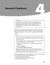
General Checkout Attention The drives in quiet mode (no beep, no memory count and checkpoint code display) when no errors are servicing might cause false errors and unnecessary replacement of the problem: 1. For an explanation of BIOS ... system. Be extremely careful during write operations such as copying, saving, or formatting. Notes • The default is found by POST. • To enable beep, memory count, and checkpoint code display when a successful POST occurs, do the following procedure to the middle position. 4. See "Starting the Setup Utility program". 2. Use the...
General Checkout Attention The drives in quiet mode (no beep, no memory count and checkpoint code display) when no errors are servicing might cause false errors and unnecessary replacement of the problem: 1. For an explanation of BIOS ... system. Be extremely careful during write operations such as copying, saving, or formatting. Notes • The default is found by POST. • To enable beep, memory count, and checkpoint code display when a successful POST occurs, do the following procedure to the middle position. 4. See "Starting the Setup Utility program". 2. Use the...
K200 Hardware Maintenance Manual
Page 26
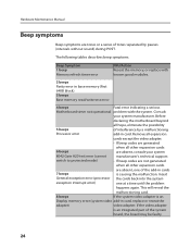
... 24 If the video adapter is causing the malfunction. The following tables describes beep symptoms. Beep Symptom 1 beep Memory refresh timer error FRU/Action Reseat the memory, or replace with known good modules. 2 beeps Parity error in card, replace or reseat the adapter) video ... POST. This will reveal the malfunctioning card. 8 beeps If the system video adapter is an Display memory error (system video add-in base memory (first 64KB block) 3 beeps Base memory read/write test error 4 beeps Fatal error indicating a serious Motherboard timer not operational problem with the...
... 24 If the video adapter is causing the malfunction. The following tables describes beep symptoms. Beep Symptom 1 beep Memory refresh timer error FRU/Action Reseat the memory, or replace with known good modules. 2 beeps Parity error in card, replace or reseat the adapter) video ... POST. This will reveal the malfunctioning card. 8 beeps If the system video adapter is an Display memory error (system video add-in base memory (first 64KB block) 3 beeps Base memory read/write test error 4 beeps Fatal error indicating a serious Motherboard timer not operational problem with the...
K200 Hardware Maintenance Manual
Page 27
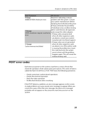
... add-in cards is causing the malfunction. POST does the following operations. • Checks some basic system-board operations • Checks the memory operation • Starts the video operation • Verifies that the boot drive is called the Power-On Self-Test, or POST. Symptom-to...the add-in card. CMOS shutdown register read/write • If beep codes are generated error when all other expansion cards Cache memory test failed are absent, one at a time until the problem happens again. Before declaring the motherboard beyond all expansion 10 beeps cards...
... add-in cards is causing the malfunction. POST does the following operations. • Checks some basic system-board operations • Checks the memory operation • Starts the video operation • Verifies that the boot drive is called the Power-On Self-Test, or POST. Symptom-to...the add-in card. CMOS shutdown register read/write • If beep codes are generated error when all other expansion cards Cache memory test failed are absent, one at a time until the problem happens again. Before declaring the motherboard beyond all expansion 10 beeps cards...
K200 Hardware Maintenance Manual
Page 29
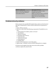
... proper Boot device or Insert Boot Media in selected Boot device Description/Action The BIOS was unable to re-test the system. 4. Memory modules d. Power-on the computer to find the failing device or adapter. Undetermined problems If this computer has a parallel ATA hard ...disk drive, make sure that the hard disk drive is jumpered as a slave. 1. Chapter 6. Power-off the computer. 2. Extended video memory e. Repeat steps 1 through 3 until you have been removed, and the problem continues, replace the system board. 27 External Cache RAM g. External devices (modem...
... proper Boot device or Insert Boot Media in selected Boot device Description/Action The BIOS was unable to re-test the system. 4. Memory modules d. Power-on the computer to find the failing device or adapter. Undetermined problems If this computer has a parallel ATA hard ...disk drive, make sure that the hard disk drive is jumpered as a slave. 1. Chapter 6. Power-off the computer. 2. Extended video memory e. Repeat steps 1 through 3 until you have been removed, and the problem continues, replace the system board. 27 External Cache RAM g. External devices (modem...

K200 Hardware Maintenance Manual
Page 35
... Guide or HMM, go to lay the computer on the heat sink retention bracket. 9. Remove the computer cover. Locate the memory module connectors. Remove the memory module being replaced by opening the retaining clips as shown. 33 Install the heat sink and fan assembly on its side. 2.... Note: For this procedure, it helps to the Support Web site at http://www.lenovo.com/support. Refer to the system board. 10. To replace a memory module: 1. Chapter 7. Replacing hardware 8. Reconnect the disconnected cables to "Removing the computer cover".
... Guide or HMM, go to lay the computer on the heat sink retention bracket. 9. Remove the computer cover. Locate the memory module connectors. Remove the memory module being replaced by opening the retaining clips as shown. 33 Install the heat sink and fan assembly on its side. 2.... Note: For this procedure, it helps to the Support Web site at http://www.lenovo.com/support. Refer to the system board. 10. To replace a memory module: 1. Chapter 7. Replacing hardware 8. Reconnect the disconnected cables to "Removing the computer cover".

K200 Hardware Maintenance Manual
Page 36
...straight out of the Safety and Warranty Guide or HMM, go to the Support Web site at http://www.lenovo.com/support. Make sure the notch on the memory aligns correctly with your computer or in the Safety and Warranty Guide that was included with the connector key... on the system board. To replace an adapter: 1. Refer to "Removing the computer cover". 2. Push the memory module straight down into the connector until the retaining clips close. 5. Refer to the "Completing the installation". Remove the computer cover. Hardware Maintenance ...
...straight out of the Safety and Warranty Guide or HMM, go to the Support Web site at http://www.lenovo.com/support. Make sure the notch on the memory aligns correctly with your computer or in the Safety and Warranty Guide that was included with the connector key... on the system board. To replace an adapter: 1. Refer to "Removing the computer cover". 2. Push the memory module straight down into the connector until the retaining clips close. 5. Refer to the "Completing the installation". Remove the computer cover. Hardware Maintenance ...

K210 User's Guide
Page 8
D-3 Microphone Connector: To connect the microphone and pass the microphone audio input to read/write data from Memory Stick /Memory Stick Pro/ Memory Stick Duo /Memory Stick Pro Due xD SD/Mini SD/SD High Capacity /Mini SD High Capacity/ MMC/ RS-MMC/MMC plus/MMC mobile CF I /O interfaces on your ....2.20 6:40:03 PM The following illustrations show connections located at the rear of all I /CF II/ MD. Following the illustrations is necessary to these. D-1 Memory card reader Connector: Able to the computer.
D-3 Microphone Connector: To connect the microphone and pass the microphone audio input to read/write data from Memory Stick /Memory Stick Pro/ Memory Stick Duo /Memory Stick Pro Due xD SD/Mini SD/SD High Capacity /Mini SD High Capacity/ MMC/ RS-MMC/MMC plus/MMC mobile CF I /O interfaces on your ....2.20 6:40:03 PM The following illustrations show connections located at the rear of all I /CF II/ MD. Following the illustrations is necessary to these. D-1 Memory card reader Connector: Able to the computer.

K210 Hardware Replacement Guide
Page 3
... 11 Removing the computer cover 11 Removing and replacing the front bezel 12 Replacing the power supply 13 Replacing the heat sink assembly 15 Replacing a memory module 16 Replacing an adapter 17 Replacing the hard disk drive 21 Replacing an optical drive 22 Replacing the system fan assembly 23 Replacing the... keyboard 25 Replacing the mouse 26 Replacing the External speaker 27 Completing the installation 27 Appendix 29 31032753 IdeaCentre K_HRG_EN.indd 32 2007.12.11 9:13:40 AM
... 11 Removing the computer cover 11 Removing and replacing the front bezel 12 Replacing the power supply 13 Replacing the heat sink assembly 15 Replacing a memory module 16 Replacing an adapter 17 Replacing the hard disk drive 21 Replacing an optical drive 22 Replacing the system fan assembly 23 Replacing the... keyboard 25 Replacing the mouse 26 Replacing the External speaker 27 Completing the installation 27 Appendix 29 31032753 IdeaCentre K_HRG_EN.indd 32 2007.12.11 9:13:40 AM
K210 Hardware Replacement Guide
Page 4
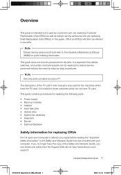
It is expected that was included with your computer. Hardware Replacement Guide 1 31032753 IdeaCentre K_HRG_EN.indd 1 2007.12.10 3:53:07 PM It is invalid for step-by customers who are replacing Customer Replaceable Units (CRUs) as well as... manual is only used by -step procedures. In this guide, CRUs and FRUs will often be replaced by Lenovo™. This guide contains procedures for replacing the following parts: • Power supply • Memory modules • Adapter • Hard disk drive • Optical drive • System fan assembly • Keyboard • ...
It is expected that was included with your computer. Hardware Replacement Guide 1 31032753 IdeaCentre K_HRG_EN.indd 1 2007.12.10 3:53:07 PM It is invalid for step-by customers who are replacing Customer Replaceable Units (CRUs) as well as... manual is only used by -step procedures. In this guide, CRUs and FRUs will often be replaced by Lenovo™. This guide contains procedures for replacing the following parts: • Power supply • Memory modules • Adapter • Hard disk drive • Optical drive • System fan assembly • Keyboard • ...

K210 Hardware Replacement Guide
Page 5
...; Always handle parts and other useful sources of information To access this information, go to http://www.lenovo.com/support. You can cause static-electricity to build up -to-date information for certain parts. Handling...Static electricity, although harmless to you handle parts and other computer components. 2 Hardware Replacement Guide 31032753 IdeaCentre K_HRG_EN.indd 2 2007.12.10 3:53:07 PM Safety information for replacing FRUs Do not attempt any... ready to other computer components carefully. Handle adapters, memory modules, system boards, and microprocessors by the edges.
...; Always handle parts and other useful sources of information To access this information, go to http://www.lenovo.com/support. You can cause static-electricity to build up -to-date information for certain parts. Handling...Static electricity, although harmless to you handle parts and other computer components. 2 Hardware Replacement Guide 31032753 IdeaCentre K_HRG_EN.indd 2 2007.12.10 3:53:07 PM Safety information for replacing FRUs Do not attempt any... ready to other computer components carefully. Handle adapters, memory modules, system boards, and microprocessors by the edges.

K210 Hardware Replacement Guide
Page 7
Microprocessor fan and heat sink Memory modules PCI adapter card 4 Hardware Replacement Guide PCI adapter connectors Power supply System fan 31032753 IdeaCentre K_HRG_EN.indd 4 2007.12.10 3:53:08 PM To remove the computer cover, refer to help you locate the various components in your computer. Chapter Locations This chapter provides illustrations to "Removing the computer cover". Locating components The following illustration will help locate the various connectors, controls and components of the computer.
Microprocessor fan and heat sink Memory modules PCI adapter card 4 Hardware Replacement Guide PCI adapter connectors Power supply System fan 31032753 IdeaCentre K_HRG_EN.indd 4 2007.12.10 3:53:08 PM To remove the computer cover, refer to help you locate the various components in your computer. Chapter Locations This chapter provides illustrations to "Removing the computer cover". Locating components The following illustration will help locate the various connectors, controls and components of the computer.

K210 Hardware Replacement Guide
Page 13
Microprocessor and heat sink Microprocessor fan connector Memory connector 1 Memory connector 2 Power connector Diskette drive connector SATA IDE connectors (2) SATA IDE connectors (2) Power fan connector Front panel connector Clear CMOS/Recovery jumper Front USB connectors (2) Serial (com2) connector Front audio connector PCI adapter connectors (1) PCI Express x1 adapter connector Battery PCI Express x16 graphics adapter connector System fan connector 12v power connector 10 Hardware Replacement Guide 31032753 IdeaCentre K_HRG_EN.indd 10 2007.12.10 3:53:18 PM
Microprocessor and heat sink Microprocessor fan connector Memory connector 1 Memory connector 2 Power connector Diskette drive connector SATA IDE connectors (2) SATA IDE connectors (2) Power fan connector Front panel connector Clear CMOS/Recovery jumper Front USB connectors (2) Serial (com2) connector Front audio connector PCI adapter connectors (1) PCI Express x1 adapter connector Battery PCI Express x16 graphics adapter connector System fan connector 12v power connector 10 Hardware Replacement Guide 31032753 IdeaCentre K_HRG_EN.indd 10 2007.12.10 3:53:18 PM

K210 Hardware Replacement Guide
Page 19
...its side. 2. Locate the memory module connectors. Refer to "Locating components". 3. To replace a memory module: 1. Remove the memory module being replaced by opening the retaining clips as shown. 16 Hardware Replacement Guide 31032753 IdeaCentre K_HRG_EN.indd 16 2007.12....10 3:53:23 PM Replacing a memory module Attention Do not remove the computer cover or attempt any repair ...Reconnect the disconnected cables to the Support Web site at http://www.lenovo.com/support.
...its side. 2. Locate the memory module connectors. Refer to "Locating components". 3. To replace a memory module: 1. Remove the memory module being replaced by opening the retaining clips as shown. 16 Hardware Replacement Guide 31032753 IdeaCentre K_HRG_EN.indd 16 2007.12....10 3:53:23 PM Replacing a memory module Attention Do not remove the computer cover or attempt any repair ...Reconnect the disconnected cables to the Support Web site at http://www.lenovo.com/support.

K210 Hardware Replacement Guide
Page 20
... Replacement Guide 17 31032753 IdeaCentre K_HRG_EN.indd 17 2007.12.10 3:53:23 PM To obtain copies of the Safety and Warranty Guide or HMM, go to the Support Web site at http://www.lenovo.com/support. Remove the computer cover. 4. Make sure the notch on the memory aligns correctly with your computer...
... Replacement Guide 17 31032753 IdeaCentre K_HRG_EN.indd 17 2007.12.10 3:53:23 PM To obtain copies of the Safety and Warranty Guide or HMM, go to the Support Web site at http://www.lenovo.com/support. Remove the computer cover. 4. Make sure the notch on the memory aligns correctly with your computer...


