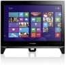
Safety and Warranty guide
Page 47
... trademarks or service marks of Intel Corporation in the U.S. and/or other countries, or both. Names or marks of Lenovo in the United States, other countries. Trademarks Lenovo and the Lenovo logo, IdeaCentre and IdeaCentre logo are trademarks of certain companies mentioned in the manuals included with your computer or this document do not necessarily...
IdeaCentre B350-B355 Hardware Maintenance Manual
Page 7
...not have the TV card. Lesen Sie unbedingt alle Hinweise vom Typ "ACHTUNG" oder "VORSICHT" in this manual is only used for IdeaCentre B350-B355 computers listed on the cover. Important Safety Information Be sure to read all caution and danger statements in dieser Dokumentation, bevor Sie ...Es importante que lea todas las declaraciones de precaución y de peligro de este manual antes de seguir las instrucciones. © Copyright Lenovo 2013 1 The description of the TV card in this book before performing any of the instructions. Veuillez lire toutes les consignes de type ...
IdeaCentre B350-B355 Hardware Maintenance Manual
Page 10
... . Ensure that another person, familiar with the reflective surface of mat to protect yourself from electrical shock. • Find the room emergency power-off power. 4 IdeaCentre B350-B355Hardware Maintenance Manual By observing the above rule, you work with powered-on a machine that power has been disconnected from passing through your back. Observe...
IdeaCentre B350-B355 Hardware Maintenance Manual
Page 12
Grounding requirements Electrical grounding of English. You can be attached to this product or attached devices. 6 IdeaCentre B350-B355Hardware Maintenance Manual DANGER Electrical current from touching your clothing. To avoid a shock hazard: • Do not connect or disconnect any equipment that meets the ...
IdeaCentre B350-B355 Hardware Maintenance Manual
Page 14
...(70.5 lbs) ≥55 kg(121.2 lbs) CAUTION: The power control button on the device and the power switch on top of rack-mounted devices. 8 IdeaCentre B350-B355Hardware Maintenance Manual The device also might have more than one power cord.
IdeaCentre B350-B355 Hardware Maintenance Manual
Page 15
... computer. General information This chapter provides general information that applies to 106KPa Electrical input: Input voltage: 90V-264V(AC) Input frequency: 47Hz-63Hz © Copyright Lenovo 2013 9 Type IdeaCentre B550-B555 This section lists the physical specifications. This section lists the physical specifications for your computer.
IdeaCentre B350-B355 Hardware Maintenance Manual
Page 20
... password will be installed. The password dialog box will be displayed. After you set an Administrator Password if you access the Lenovo BIOS Setup Utility program. To delete a previously set an Administrator Password, do the following : 1. Return to confirm, then... Administrator Password, Enter blank fields for maintaining the settings of letters and numbers up to 16 character (a-z, and 0-9). 14 IdeaCentre B350-B355Hardware Maintenance Manual A setup notice will be installed. Select Save changes and Exit from changing configuration settings. The password dialog...
IdeaCentre B350-B355 Hardware Maintenance Manual
Page 22
... Selecting a startup device from the Startup Device Menu does not permanently change the configured startup device sequence, do the following: 1. From the Lenovo BIOS Setup Utility program main menu, select the Startup option. 3. Select Save changes and Exit from the menu. If you do not want ...the Enter key, and select the devices for the Primary Boot Sequence. Use - and ¯ arrows to startup from the menu. 16 IdeaCentre B350-B355Hardware Maintenance Manual Turn off your computer does not boot from or include the device in the boot sequence. 5. Note: If the Startup ...
IdeaCentre B350-B355 Hardware Maintenance Manual
Page 26
... system is called the Power-On Self-Test, or POST. Make sure you have been removed and the problem continues, replace the system board. 20 IdeaCentre B350-B355Hardware Maintenance Manual Remove or disconnect the following : • Checks some basic system-board operations • Checks that the memory is working POST Error Message...
IdeaCentre B350-B355 Hardware Maintenance Manual
Page 28
Power button 3. USB 3.0 connector 4. Headphone connector 3 4 5 6 7 5. Memory card reader 22 IdeaCentre B350-B355Hardware Maintenance Manual Microphone connector 6. USB 3.0 connector 7. Optical drive 2. Left and right view The following illustration shows the location of connectors, controls and components on the left and right side of the computer. 1 2 1.
IdeaCentre B350-B355 Hardware Maintenance Manual
Page 30
... shows the components that make up your computer. 1 23 2 22 3 21 4 20 5 19 6 7 8 18 17 9 10 16 15 11 14 12 13 1. Computer stand 24 IdeaCentre B350-B355Hardware Maintenance Manual
IdeaCentre B350-B355 Hardware Maintenance Manual
Page 32
... (2) 18. Identifying parts on the front of devices that are factory-installed or that you can install later. System fan connector 1 3. Motherboard power connector 2 26 IdeaCentre B350-B355Hardware Maintenance Manual Memory slot 24. It provides basic computing functions and supports a variety of the motherboard. 25 1 24 2 3 23 4 5 6 7 8 9 10 22 11 12 13...
IdeaCentre B350-B355 Hardware Maintenance Manual
Page 34
... cables attached to the computer. Note: Your keyboard will be replaced using the same method. Note: The mouse can be connected to "Rear view". 28 IdeaCentre B350-B355Hardware Maintenance Manual To replace the power cord and power adapter: Step 1. Remove any other cables that are connected to "Left and right view" and...
IdeaCentre B350-B355 Hardware Maintenance Manual
Page 36
Disconnect all attached devices. Refer to "Left and right view" and "Rear view" for help with locating the various connectors. Lenovo recommends that you use a blanket, towel, or other damage. To reinstall the computer cover: a. Step 3. Remove any media (disks, CDs, ... turn off the computer and wait 3 to 5 minutes to the computer. Line up the cover pieces with locating the various connectors. 30 IdeaCentre B350-B355Hardware Maintenance Manual To remove the computer stand: Step 1. Removing the computer stand Note: Turn off the computer and all cables attached to ...
IdeaCentre B350-B355 Hardware Maintenance Manual
Page 38
... to remove it from scratches or other cables that you use a blanket, towel, or other soft cloth to the computer. Lenovo recommends that are connected to "Removing the rear cover". 32 IdeaCentre B350-B355Hardware Maintenance Manual Step 3. Disconnect all cables attached to protect the computer screen from its socket. Step 6. Replacing the hard...
IdeaCentre B350-B355 Hardware Maintenance Manual
Page 40
Step 5. Step 7. Push down the pin that secure the optical drive to the metal bracket. 1 Step 8. Remove the 2 screws that locks the optical disk drive to the disk. 2 3 34 IdeaCentre B350-B355Hardware Maintenance Manual Push a small iron stick (paper clip) into the small hole on the optical drive cover so that secure the cover to the chassis then use the screwdriver push the disk out. 1 2 1 2 Step 6. Use a small flat head screwdriver to "Removing the rear cover". Step 4. Refer to press and push out the pins that the disk springs out as shown. Remove the rear cover.
IdeaCentre B350-B355 Hardware Maintenance Manual
Page 42
... cover upward to "Left and right view" and "Rear view" for this procedure. Step 10. Lenovo recommends that you use a blanket, towel, or other cables that secure the middle cover to "Removing the middle cover". 36 IdeaCentre B350-B355Hardware Maintenance Manual Step 7. Disconnect all attached devices. Remove the computer stand. Refer to "Removing...
IdeaCentre B350-B355 Hardware Maintenance Manual
Page 44
..., or memory cards) from electrical outlets. Refer to the computer. Remove the computer stand. Remove the EMI cover. Refer to "Removing the EMI cover". 38 IdeaCentre B350-B355Hardware Maintenance Manual
IdeaCentre B350-B355 Hardware Maintenance Manual
Page 46
Disconnect the antenna cables from electrical outlets. Step 13. Remove any other cables that secures the Wi-Fi card to "Removing the EMI cover". 40 IdeaCentre B350-B355Hardware Maintenance Manual Refer to "Left and right view" and "Rear view" for help with the screw. Remove the computer stand. Refer to the computer. ...
IdeaCentre B350-B355 Hardware Maintenance Manual
Page 48
...cables that secure the power supply to the metal bracket. Refer to the motherboard. Refer to "Removing the computer stand". Step 12. Lenovo recommends that secure the power supply connector to the chassis, and then lift up the new power supply, secure it cool down before ...: Turn off the computer and all attached devices. Step 2. Remove any other damage. Step 13. Refer to "Removing the EMI cover". 42 IdeaCentre B350-B355Hardware Maintenance Manual To replace the system fan Step 1. Remove the EMI cover. Remove the rear cover. Remove the two screws that you use ...