Lenovo C260 All-In-One PC Hardware Maintenance Manual
Page 5
...inspection guide 5 Handling electrostatic discharge-sensitive devices 5 Grounding requirements 6 Safety notices 6 Chapter 3. Using the Setup Utility. . . 13 Starting the Lenovo BIOS Setup Utility program . 13 Viewing and changing settings 13 Using passwords 13 Enabling or disabling a device 15 Selecting a startup device 16 Changing ... system 32 Replacing the indicator board 33 Replacing the power switch board 33 Replacing the system fan 34 Replacing the motherboard 35 Replacing the heat-sink 37 Replacing the camera 38 Replacing the converter board 39 Replacing the LED panel 41 ...
...inspection guide 5 Handling electrostatic discharge-sensitive devices 5 Grounding requirements 6 Safety notices 6 Chapter 3. Using the Setup Utility. . . 13 Starting the Lenovo BIOS Setup Utility program . 13 Viewing and changing settings 13 Using passwords 13 Enabling or disabling a device 15 Selecting a startup device 16 Changing ... system 32 Replacing the indicator board 33 Replacing the power switch board 33 Replacing the system fan 34 Replacing the motherboard 35 Replacing the heat-sink 37 Replacing the camera 38 Replacing the converter board 39 Replacing the LED panel 41 ...
Lenovo C260 All-In-One PC Hardware Maintenance Manual
Page 26
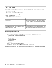
... and set . Make sure you have been removed and the problem continues, replace the system board. 20 Lenovo C260 All-In-One PC Hardware Maintenance Manual Remove or disconnect the following : • Checks some basic motherboard operations • Checks that the memory is working correctly • Starts video operations • Verifies that the...
... and set . Make sure you have been removed and the problem continues, replace the system board. 20 Lenovo C260 All-In-One PC Hardware Maintenance Manual Remove or disconnect the following : • Checks some basic motherboard operations • Checks that the memory is working correctly • Starts video operations • Verifies that the...

Lenovo C260 All-In-One PC Hardware Maintenance Manual
Page 38
..., CDs, DVDs, or memory cards) from the socket. Disconnect the antenna and data cables from electrical outlets. To replace the speaker system: 32 Lenovo C260 All-In-One PC Hardware Maintenance Manual d. Step 2. Step 4. Step 5. Step 6. Refer to the computer. Connect the antenna cables to the new...the screw. Remove the rear cover. Step 9. Unplug all attached devices. Step 8. Step 10. Remove the screw that are connected to the motherboard. Step 7. Reattach the rear cover, stand and stand cover. Insert the new Wi-Fi card into the card port and secure it cool ...
..., CDs, DVDs, or memory cards) from the socket. Disconnect the antenna and data cables from electrical outlets. To replace the speaker system: 32 Lenovo C260 All-In-One PC Hardware Maintenance Manual d. Step 2. Step 4. Step 5. Step 6. Refer to the computer. Connect the antenna cables to the new...the screw. Remove the rear cover. Step 9. Unplug all attached devices. Step 8. Step 10. Remove the screw that are connected to the motherboard. Step 7. Reattach the rear cover, stand and stand cover. Insert the new Wi-Fi card into the card port and secure it cool ...

Lenovo C260 All-In-One PC Hardware Maintenance Manual
Page 39
... 7. To install the new speaker system: a. Replacing the indicator board [A60110] Error in document "D:\All Pros\C260\HMM\Lenovo C260 Hardware Maintainence Manual.ditamap" on motherboard. Remove any other cables that are connected to "Left and right view" and "Rear view" for help with the rubber screws. Step 2.... to let it cool down the operating system, and turn off the computer and wait 3 to 5 minutes to open document "D:\All Pros\C260\HMM\Replacing the indicator board.dita" Replacing the power switch board Note: Turn off the computer and all attached devices. To replace the power...
... 7. To install the new speaker system: a. Replacing the indicator board [A60110] Error in document "D:\All Pros\C260\HMM\Lenovo C260 Hardware Maintainence Manual.ditamap" on motherboard. Remove any other cables that are connected to "Left and right view" and "Rear view" for help with the rubber screws. Step 2.... to let it cool down the operating system, and turn off the computer and wait 3 to 5 minutes to open document "D:\All Pros\C260\HMM\Replacing the indicator board.dita" Replacing the power switch board Note: Turn off the computer and all attached devices. To replace the power...

Lenovo C260 All-In-One PC Hardware Maintenance Manual
Page 40
... for help with locating the various connectors. Disconnect all attached devices. Step 4. Step 5. Refer to "Removing the rear cover". 34 Lenovo C260 All-In-One PC Hardware Maintenance Manual Disconnect the power switch board cable from electrical outlets. Remove any media (disks, CDs, DVDs ...Left and right view" and "Rear view" for help with locating the various connectors. Disconnect all power cords from the connector on the motherboard. 1 Step 7. This includes power cords, input/output (I /O) cables, and any other cables that are connected to the rear cover...
... for help with locating the various connectors. Disconnect all attached devices. Step 4. Step 5. Refer to "Removing the rear cover". 34 Lenovo C260 All-In-One PC Hardware Maintenance Manual Disconnect the power switch board cable from electrical outlets. Remove any media (disks, CDs, DVDs ...Left and right view" and "Rear view" for help with locating the various connectors. Disconnect all power cords from the connector on the motherboard. 1 Step 7. This includes power cords, input/output (I /O) cables, and any other cables that are connected to the rear cover...

Lenovo C260 All-In-One PC Hardware Maintenance Manual
Page 41
... the rear cover". Step 3. Remove all cables attached to "Replacing the Wi-Fi card". Step 6. Step 7. Refer to the connector on the motherboard. Step 4. This includes power cords, input/output (I/O) cables, and any media (disks, CDs, DVDs, or memory cards) from electrical outlets.... Refer to the computer. Lift up the new system fan with the mounting holes on the motherboard. Disconnect all memory modules. Secure the new system fan to let it into position. Step 5. Disconnect the power cable from the...
... the rear cover". Step 3. Remove all cables attached to "Replacing the Wi-Fi card". Step 6. Step 7. Refer to the connector on the motherboard. Step 4. This includes power cords, input/output (I/O) cables, and any media (disks, CDs, DVDs, or memory cards) from electrical outlets.... Refer to the computer. Lift up the new system fan with the mounting holes on the motherboard. Disconnect all memory modules. Secure the new system fan to let it into position. Step 5. Disconnect the power cable from the...

Lenovo C260 All-In-One PC Hardware Maintenance Manual
Page 42
...heat-sink, Wi-Fi card, memory modules to the Wi-Fi card. d. Connect all the cables connected to the motherboard. To install the new motherboard: a. b. Line up to the new motherboard. Remove the 8 screws that secure the motherboard to the rear cover and lift it up the holes on the new... the rear cover and secure the new motherboard with the screw. Remove all the cables to remove it with the 8 screws. c. Remove the heat-sink as shown. Step 12. Step 9. Reattach the rear cover, stand and stand cover. 36 Lenovo C260 All-In-One PC Hardware Maintenance Manual ...
...heat-sink, Wi-Fi card, memory modules to the Wi-Fi card. d. Connect all the cables connected to the motherboard. To install the new motherboard: a. b. Line up to the new motherboard. Remove the 8 screws that secure the motherboard to the rear cover and lift it up the holes on the new... the rear cover and secure the new motherboard with the screw. Remove all the cables to remove it with the 8 screws. c. Remove the heat-sink as shown. Step 12. Step 9. Reattach the rear cover, stand and stand cover. 36 Lenovo C260 All-In-One PC Hardware Maintenance Manual ...

Lenovo C260 All-In-One PC Hardware Maintenance Manual
Page 43
...and wait 3 to 5 minutes to "Left and right view" and "Rear view" for help with the mounting holes on the motherboard. d. Reattach the motherboard. Step 7. Disconnect all attached devices. Remove the rear cover. Attention: Place the heat-sink upside down the operating system, and ...off the computer and all cables attached to prevent thermal grease contaminating other cables that secure the heat-sink module to "Replacing the motherboard". c. e. Replacing hardware 37 Remove the 6 screws that are connected to remove it cool down before removing the rear cover. ...
...and wait 3 to 5 minutes to "Left and right view" and "Rear view" for help with the mounting holes on the motherboard. d. Reattach the motherboard. Step 7. Disconnect all attached devices. Remove the rear cover. Attention: Place the heat-sink upside down the operating system, and ...off the computer and all cables attached to prevent thermal grease contaminating other cables that secure the heat-sink module to "Replacing the motherboard". c. e. Replacing hardware 37 Remove the 6 screws that are connected to remove it cool down before removing the rear cover. ...


