Hardware Maintenance Manual
Page 3
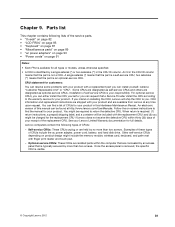
...2. Removing and replacing a FRU 43 General guidelines 43 1010 Battery pack 44 1020 Bottom slot cover 44 1030 Optical drive 45 1040 Memory modules 46 1050 Hard disk drive assembly 47 1060 PCI Express Mini Card for replacing a system board 28 Important information about replacing RoHS... 2020 Camera 74 2030 LCD panel, LCD cable, and hinges . . . . 75 2040 Antenna assembly and LCD rear cover . . . 77 Chapter 8. Lenovo B590 37 Specifications 37 Status indicators 38 Fn key combinations 39 Chapter 6. Parts list 81 Overall 82 LCD FRUs 85 Keyboard 87 Miscellaneous parts 89 ac...
...2. Removing and replacing a FRU 43 General guidelines 43 1010 Battery pack 44 1020 Bottom slot cover 44 1030 Optical drive 45 1040 Memory modules 46 1050 Hard disk drive assembly 47 1060 PCI Express Mini Card for replacing a system board 28 Important information about replacing RoHS... 2020 Camera 74 2030 LCD panel, LCD cable, and hinges . . . . 75 2040 Antenna assembly and LCD rear cover . . . 77 Chapter 8. Lenovo B590 37 Specifications 37 Status indicators 38 Fn key combinations 39 Chapter 6. Parts list 81 Overall 82 LCD FRUs 85 Keyboard 87 Miscellaneous parts 89 ac...
Hardware Maintenance Manual
Page 43
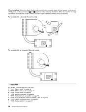
...rate 3 (DDR3) synchronous dynamic random access memory (SDRAM) Storage device • 2.5-inch (7 mm height or 9.5 mm height) hard disk drive • mSATA solid state drive (on page 39 Specifications This topic lists the physical features for the Lenovo B590 models. Processor • Windows 7: To ...view the system properties of the screen to display the charms. Then click Settings ➙ PC info. Lenovo B590 This chapter presents the following product-specific service references and parts information: • "Specifications" on page 37 • "Status indicators...
...rate 3 (DDR3) synchronous dynamic random access memory (SDRAM) Storage device • 2.5-inch (7 mm height or 9.5 mm height) hard disk drive • mSATA solid state drive (on page 39 Specifications This topic lists the physical features for the Lenovo B590 models. Processor • Windows 7: To ...view the system properties of the screen to display the charms. Then click Settings ➙ PC info. Lenovo B590 This chapter presents the following product-specific service references and parts information: • "Specifications" on page 37 • "Status indicators...
Hardware Maintenance Manual
Page 52
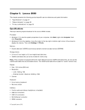
Step 1 Screw (quantity) M2 × 3 mm, flat-head, nylon-coated (2) 1040 Memory modules For access, remove these FRUs in the direction shown by the arrow 3 . Insert a screwdriver into the screw hole 2 and push the optical drive in order: • "1010 Battery pack" on page 44 • "1020 Bottom slot cover" on page 44 46 Hardware Maintenance Manual 1 2 Color Black Torque 1.85 kgf-cm Then remove the optical drive. 3 2 Removal steps of optical drive bezel and optical drive bracket Remove the screws 1 and then remove the optical drive bracket.
Step 1 Screw (quantity) M2 × 3 mm, flat-head, nylon-coated (2) 1040 Memory modules For access, remove these FRUs in the direction shown by the arrow 3 . Insert a screwdriver into the screw hole 2 and push the optical drive in order: • "1010 Battery pack" on page 44 • "1020 Bottom slot cover" on page 44 46 Hardware Maintenance Manual 1 2 Color Black Torque 1.85 kgf-cm Then remove the optical drive. 3 2 Removal steps of optical drive bezel and optical drive bracket Remove the screws 1 and then remove the optical drive bracket.
Hardware Maintenance Manual
Page 53
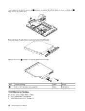
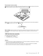
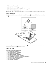
...used on the computer you are servicing, the card must be installed in SLOT-0 ( a : lower slot), but not in SLOT-1 ( b : upper slot). Removal steps of memory modules Release the two latches on both edges of the socket at the same time in the direction shown by the arrows 1 , and then unplug... the memory module in the direction shown by the arrow 2 . 1 1 2 Note: If only one memory module is in suspend mode. Press the memory module firmly, and pivot it until it snaps into the socket. Chapter 7. Removing and replacing...
...used on the computer you are servicing, the card must be installed in SLOT-0 ( a : lower slot), but not in SLOT-1 ( b : upper slot). Removal steps of memory modules Release the two latches on both edges of the socket at the same time in the direction shown by the arrows 1 , and then unplug... the memory module in the direction shown by the arrow 2 . 1 1 2 Note: If only one memory module is in suspend mode. Press the memory module firmly, and pivot it until it snaps into the socket. Chapter 7. Removing and replacing...
Hardware Maintenance Manual
Page 69
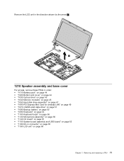
... order: • "1010 Battery pack" on page 44 • "1020 Bottom slot cover" on page 44 • "1030 Optical drive" on page 45 • "1040 Memory modules" on page 46 • "1050 Hard disk drive assembly" on page 47 • "1060 PCI Express Mini Card for wireless LAN" on page 49...
... order: • "1010 Battery pack" on page 44 • "1020 Bottom slot cover" on page 44 • "1030 Optical drive" on page 45 • "1040 Memory modules" on page 46 • "1050 Hard disk drive assembly" on page 47 • "1060 PCI Express Mini Card for wireless LAN" on page 49...
Hardware Maintenance Manual
Page 71
... order: • "1010 Battery pack" on page 44 • "1020 Bottom slot cover" on page 44 • "1030 Optical drive" on page 45 • "1040 Memory modules" on page 46 • "1050 Hard disk drive assembly" on page 47 • "1060 PCI Express Mini Card for wireless LAN" on page 49...
... order: • "1010 Battery pack" on page 44 • "1020 Bottom slot cover" on page 44 • "1030 Optical drive" on page 45 • "1040 Memory modules" on page 46 • "1050 Hard disk drive assembly" on page 47 • "1060 PCI Express Mini Card for wireless LAN" on page 49...
Hardware Maintenance Manual
Page 72
... order: • "1010 Battery pack" on page 44 • "1020 Bottom slot cover" on page 44 • "1030 Optical drive" on page 45 • "1040 Memory modules" on page 46 • "1050 Hard disk drive assembly" on page 47 • "1060 PCI Express Mini Card for wireless LAN" on page 49...
... order: • "1010 Battery pack" on page 44 • "1020 Bottom slot cover" on page 44 • "1030 Optical drive" on page 45 • "1040 Memory modules" on page 46 • "1050 Hard disk drive assembly" on page 47 • "1060 PCI Express Mini Card for wireless LAN" on page 49...
Hardware Maintenance Manual
Page 74
... order: • "1010 Battery pack" on page 44 • "1020 Bottom slot cover" on page 44 • "1030 Optical drive" on page 45 • "1040 Memory modules" on page 46 • "1050 Hard disk drive assembly" on page 47 • "1060 PCI Express Mini Card for wireless LAN" on page 49...
... order: • "1010 Battery pack" on page 44 • "1020 Bottom slot cover" on page 44 • "1030 Optical drive" on page 45 • "1040 Memory modules" on page 46 • "1050 Hard disk drive assembly" on page 47 • "1060 PCI Express Mini Card for wireless LAN" on page 49...
Hardware Maintenance Manual
Page 75
... order: • "1010 Battery pack" on page 44 • "1020 Bottom slot cover" on page 44 • "1030 Optical drive" on page 45 • "1040 Memory modules" on page 46 • "1050 Hard disk drive assembly" on page 47 • "1060 PCI Express Mini Card for wireless LAN" on page 49...
... order: • "1010 Battery pack" on page 44 • "1020 Bottom slot cover" on page 44 • "1030 Optical drive" on page 45 • "1040 Memory modules" on page 46 • "1050 Hard disk drive assembly" on page 47 • "1060 PCI Express Mini Card for wireless LAN" on page 49...
Hardware Maintenance Manual
Page 77
... order: • "1010 Battery pack" on page 44 • "1020 Bottom slot cover" on page 44 • "1030 Optical drive" on page 45 • "1040 Memory modules" on page 46 • "1050 Hard disk drive assembly" on page 47 • "1060 PCI Express Mini Card for wireless LAN" on page 49...
... order: • "1010 Battery pack" on page 44 • "1020 Bottom slot cover" on page 44 • "1030 Optical drive" on page 45 • "1040 Memory modules" on page 46 • "1050 Hard disk drive assembly" on page 47 • "1060 PCI Express Mini Card for wireless LAN" on page 49...
Hardware Maintenance Manual
Page 86
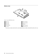
Lenovo B590 bottom view 1 Battery lock 2 Battery pack 3 Battery latch 4 Security keyhole 5 Fan louvers 6 Monitor connector 7 Ethernet connector 8 HDMI port 9 USB 3.0 connector 10 Bottom slot cover1 1 The memory modules, hard disk drive, and wireless cards are located underneath the bottom slot cover. 80 Hardware Maintenance Manual Bottom view 1 2 3 4 10 5 6 7 8 9 Figure 2.
Lenovo B590 bottom view 1 Battery lock 2 Battery pack 3 Battery latch 4 Security keyhole 5 Fan louvers 6 Monitor connector 7 Ethernet connector 8 HDMI port 9 USB 3.0 connector 10 Bottom slot cover1 1 The memory modules, hard disk drive, and wireless cards are located underneath the bottom slot cover. 80 Hardware Maintenance Manual Bottom view 1 2 3 4 10 5 6 7 8 9 Figure 2.
Hardware Maintenance Manual
Page 87
...CRUs. Installation of your product. You can find the manual for your product in the CRU ID column means that the part is your Lenovo Limited Warranty documentation for your product. Follow the on product design might be included with finger print reader and touch pad. - You ...might include the memory module, wireless card, keyboard, and palm rest with the replacement CRU; and (2) you can resolve some problems with your product with your ...
...CRUs. Installation of your product. You can find the manual for your product in the CRU ID column means that the part is your Lenovo Limited Warranty documentation for your product. Follow the on product design might be included with finger print reader and touch pad. - You ...might include the memory module, wireless card, keyboard, and palm rest with the replacement CRU; and (2) you can resolve some problems with your product with your ...
Hardware Maintenance Manual
Page 89
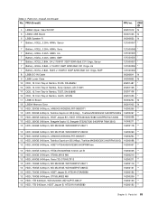
....7mm Tray-in Rambo, TSST, SN-208AB 25201108 * 10 ODD, 12.7mm Tray-in Rambo, HLDS, GT50N 25201635 * 11 LB58 IO Board 90000234 N 12 LB59A Memory Door 90201905 N 13 HDD, 320GB 5400rpm,, MN500S WD3200LPVT-08G33T1 16200265 ** 13 HDD, 320GB 5400rpm, Toshiba Capricorn BS (H6sp),Toshiba MK3265GSX 5400RPM 320G 16200097 ** 13...
....7mm Tray-in Rambo, TSST, SN-208AB 25201108 * 10 ODD, 12.7mm Tray-in Rambo, HLDS, GT50N 25201635 * 11 LB58 IO Board 90000234 N 12 LB59A Memory Door 90201905 N 13 HDD, 320GB 5400rpm,, MN500S WD3200LPVT-08G33T1 16200265 ** 13 HDD, 320GB 5400rpm, Toshiba Capricorn BS (H6sp),Toshiba MK3265GSX 5400RPM 320G 16200097 ** 13...


