
User Manual
Page 75
...For additional information, refer to test devices, diagnose problems, create bootable diagnostic media, update system drivers, and review system information. The Lenovo System Toolbox also has problem determination aids that works through the Windows operating system and enables you maintain your ...the PC-Doctor for Rescue and Recovery if you are unable to a Lenovo technical support representative. v PC-Doctor for computer problems, access the Lenovo troubleshooting center, update system drivers, and review system information. If you are unable to isolate and repair the problem ...
...For additional information, refer to test devices, diagnose problems, create bootable diagnostic media, update system drivers, and review system information. The Lenovo System Toolbox also has problem determination aids that works through the Windows operating system and enables you maintain your ...the PC-Doctor for Rescue and Recovery if you are unable to a Lenovo technical support representative. v PC-Doctor for computer problems, access the Lenovo troubleshooting center, update system drivers, and review system information. If you are unable to isolate and repair the problem ...

Hardware Maintenance Manual
Page 41
...-controlled settings that works through the Windows operating system and enables you want to a Lenovo technical support representative. Lenovo System Toolbox The Lenovo System Toolbox is part of the Lenovo System Toolbox and PC-Doctor for additional help. 6. If you still suspect a problem... program opens automatically. You can cause hardware failures. To run PC-Doctor for computer problems, access the Lenovo troubleshooting center, update system drivers, and review system information. Press the F1 key for DOS diagnostic programs from the Rescue and Recovery workspace, do the...
...-controlled settings that works through the Windows operating system and enables you want to a Lenovo technical support representative. Lenovo System Toolbox The Lenovo System Toolbox is part of the Lenovo System Toolbox and PC-Doctor for additional help. 6. If you still suspect a problem... program opens automatically. You can cause hardware failures. To run PC-Doctor for computer problems, access the Lenovo troubleshooting center, update system drivers, and review system information. Press the F1 key for DOS diagnostic programs from the Rescue and Recovery workspace, do the...
Hardware Maintenance Manual
Page 50
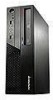
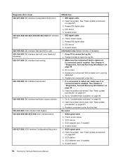
..., if necessary 1. See "Flash update procedures" on page 521 3. See "Flash update procedures" on page 521 3. Flash the system. System board 1. Restart the test to review the log file 2. Diagnostic Error Code 000-000-XXX BIOS Test Passed 000-002-XXX BIOS Timeout 000-024-XXX BIOS Addressing test failure 000...
..., if necessary 1. See "Flash update procedures" on page 521 3. See "Flash update procedures" on page 521 3. Flash the system. System board 1. Restart the test to review the log file 2. Diagnostic Error Code 000-000-XXX BIOS Test Passed 000-002-XXX BIOS Timeout 000-024-XXX BIOS Addressing test failure 000...
Hardware Maintenance Manual
Page 52
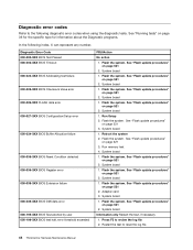
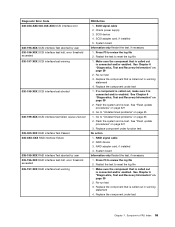
... to "Undetermined problems" on IRQ2 2. See Chapter 6 "Diagnostics, Test and Recovery Information" on page 65 1. System board 1. Device on page 65 2. Restart the test to review the log file 2. Go to "Undetermined problems" on page 39 2. System board 1. Power-off /on IRQ1 2. System board Information only Restart the test, if necessary...
... to "Undetermined problems" on IRQ2 2. See Chapter 6 "Diagnostics, Test and Recovery Information" on page 65 1. System board 1. Device on page 65 2. Restart the test to review the log file 2. Go to "Undetermined problems" on page 39 2. System board 1. Power-off /on IRQ1 2. System board Information only Restart the test, if necessary...
Hardware Maintenance Manual
Page 54
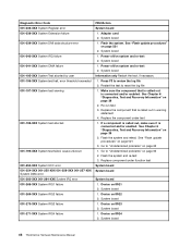
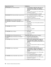
... 3. System board 1. Video card, if installed 2. System board Information only Restart the test, if necessary 1. Replace the component called out in warning statement 4. Go to review the log file 2. System board 1. System board 1. Press F3 to "Undetermined problems" on page 39 2. Flash the system and re-test. Video card, if installed...
... 3. System board 1. Video card, if installed 2. System board Information only Restart the test, if necessary 1. Replace the component called out in warning statement 4. Go to review the log file 2. System board 1. System board 1. Press F3 to "Undetermined problems" on page 39 2. Flash the system and re-test. Video card, if installed...
Hardware Maintenance Manual
Page 55
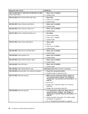
... and/or enabled 2. See "Flash update procedures" on page 521 3. Run setup, enable port 3. Replace component under function test 1. Diskette drive 3. Diskette drive 3. Symptom-to review the log file 2. Video card, if installed 2. System board Information only Restart the test, if necessary 1. See "Flash update procedures" on page 521 3. Replace component...
... and/or enabled 2. See "Flash update procedures" on page 521 3. Run setup, enable port 3. Replace component under function test 1. Diskette drive 3. Diskette drive 3. Symptom-to review the log file 2. Video card, if installed 2. System board Information only Restart the test, if necessary 1. See "Flash update procedures" on page 521 3. Replace component...

Hardware Maintenance Manual
Page 56
... page 521 3. Replace the component under function test 1. See "Flash update procedures" on page 39 2. Remove external parallel device, if present 2. Wrap plug 2. Go to review the log file 2. See "Flash update procedures" on page 39 2. See Chapter 6 "Diagnostics, Test and Recovery Information" on page 521 3. Press F3 to "Undetermined problems...
... page 521 3. Replace the component under function test 1. See "Flash update procedures" on page 39 2. Remove external parallel device, if present 2. Wrap plug 2. Go to review the log file 2. See "Flash update procedures" on page 39 2. See Chapter 6 "Diagnostics, Test and Recovery Information" on page 521 3. Press F3 to "Undetermined problems...
Hardware Maintenance Manual
Page 57
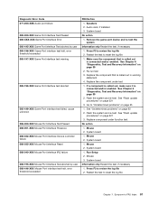
... board System board 1. See "Flash update procedures" on page 521 3. Remove USB device(s) and re-test 2. See "Flash update procedures" on page 521 3. Symptom-to review the log file 2. Make sure the component that is called out is connected and/or enabled 2. Flash the system and re-test. System board 1. Flash...
... board System board 1. See "Flash update procedures" on page 521 3. Remove USB device(s) and re-test 2. See "Flash update procedures" on page 521 3. Symptom-to review the log file 2. Make sure the component that is called out is connected and/or enabled 2. Flash the system and re-test. System board 1. Flash...
Hardware Maintenance Manual
Page 58
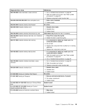
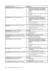
... enabled. Replace the component under test 018-198-XXX PCI Card test aborted 1. If a component is called out in warning statement 4. Go to review the log file 2. Riser card, if installed 2. System board 018-195-XXX PCI Card Test aborted by user Information only Restart the test, if... file 018-197-XXX PCI Card test warning 1. See "Flash update procedures" on page 65 52 ThinkCentre Hardware Maintenance Manual Press F3 to review the log file 2. Replace the component that is called out in warning statement 4. Diagnostic Error Code FRU/Action 015-195-XXX USB port ...
... enabled. Replace the component under test 018-198-XXX PCI Card test aborted 1. If a component is called out in warning statement 4. Go to review the log file 2. Riser card, if installed 2. System board 018-195-XXX PCI Card Test aborted by user Information only Restart the test, if... file 018-197-XXX PCI Card test warning 1. See "Flash update procedures" on page 65 52 ThinkCentre Hardware Maintenance Manual Press F3 to review the log file 2. Replace the component that is called out in warning statement 4. Diagnostic Error Code FRU/Action 015-195-XXX USB port ...
Hardware Maintenance Manual
Page 59
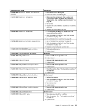
... 2. Check power supply voltages 3. Replace the component under test 1. Riser card, if installed 3. Reseat IDE signal cable 4. Flash the system and re-test. Go to review the log file 2. IDE device 5. See "Flash update procedures" on page 65 2. PCI card 2. IDE signal cable 2. System board Information only Restart the test, if...
... 2. Check power supply voltages 3. Replace the component under test 1. Riser card, if installed 3. Reseat IDE signal cable 4. Flash the system and re-test. Go to review the log file 2. IDE device 5. See "Flash update procedures" on page 65 2. PCI card 2. IDE signal cable 2. System board Information only Restart the test, if...
Hardware Maintenance Manual
Page 60
Flash the system. Restart the test to review the log file 2. Flash the system and re-test. Flash the system and re-test. SCSI device 4. SCSI adapter card, if installed 5. Diagnostic Error Code ...
Flash the system. Restart the test to review the log file 2. Flash the system and re-test. Flash the system and re-test. SCSI device 4. SCSI adapter card, if installed 5. Diagnostic Error Code ...
Hardware Maintenance Manual
Page 61
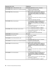
Check power supply 3. SCSI device 4. Restart the test to review the log file 2. Replace the component that is called out is connected and/or enabled. Replace the component under function test No action 1. See Chapter 6 "... test, if necessary 1. Press F3 to reset the log file 1. Flash the system and re-test. Go to -FRU Index 55 Restart the test to review the log file 2. Diagnostic Error Code 030-03X-XXX 030-04X-XXX SCSI interface error 030-195-XXX SCSI interface Test aborted by user 030...
Check power supply 3. SCSI device 4. Restart the test to review the log file 2. Replace the component that is called out is connected and/or enabled. Replace the component under function test No action 1. See Chapter 6 "... test, if necessary 1. Press F3 to reset the log file 1. Flash the system and re-test. Go to -FRU Index 55 Restart the test to review the log file 2. Diagnostic Error Code 030-03X-XXX 030-04X-XXX SCSI interface error 030-195-XXX SCSI interface Test aborted by user 030...
Hardware Maintenance Manual
Page 62
... in warning statement 4. If a component is connected and/or enabled. Replace component under function test No action 1. Run Setup 2. Run Setup 2. Restart the test to review the log file 2. See Chapter 6 "Diagnostics, Test and Recovery Information" on page 521 3. Flash the system and re-test. If a component is called out is...
... in warning statement 4. If a component is connected and/or enabled. Replace component under function test No action 1. Run Setup 2. Run Setup 2. Restart the test to review the log file 2. See Chapter 6 "Diagnostics, Test and Recovery Information" on page 521 3. Flash the system and re-test. If a component is called out is...
Hardware Maintenance Manual
Page 63
System board No action 1. Replace the component that is called out is connected and/or enabled. Mouse 2. Mouse 3. Symptom-to review the log file 2. Flash the system and re-test. System board Information only Restart the test, if necessary 1. Press F3 to -FRU ... it is called out in warning statement 4. Flash the system and re-test. Re-run test 3. If a component is connected and/or enabled. Go to review the log file 2. See "Flash update procedures" on page 521 3. Replace component under test 1. System board 1. Audio card, if installed 3. See "Flash ...
System board No action 1. Replace the component that is called out is connected and/or enabled. Mouse 2. Mouse 3. Symptom-to review the log file 2. Flash the system and re-test. System board Information only Restart the test, if necessary 1. Press F3 to -FRU ... it is called out in warning statement 4. Flash the system and re-test. Re-run test 3. If a component is connected and/or enabled. Go to review the log file 2. See "Flash update procedures" on page 521 3. Replace component under test 1. System board 1. Audio card, if installed 3. See "Flash ...
Hardware Maintenance Manual
Page 64
... action 1. Flash system 2. Flash the system. Microprocessor(s) 2. System board Information only Restart the test, if necessary 58 ThinkCentre Hardware Maintenance Manual Restart the test to review the log file 2. See Chapter 6 "Diagnostics, Test and Recovery Information" on page 65 1. Replace component under function test No action 1. Replace the component that is...
... action 1. Flash system 2. Flash the system. Microprocessor(s) 2. System board Information only Restart the test, if necessary 58 ThinkCentre Hardware Maintenance Manual Restart the test to review the log file 2. See Chapter 6 "Diagnostics, Test and Recovery Information" on page 65 1. Replace component under function test No action 1. Replace the component that is...
Hardware Maintenance Manual
Page 65
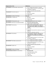
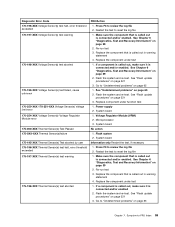
Restart the test to review the log file 2. Go to "Undetermined problems" on page 521 3. Flash the system and re-test. Press F3 to reset the log file 1. Make sure ... to -FRU Index 59 Flash the system and re-test. Replace the component that is called out is called out in warning statement 4. Symptom-to review the log file 2. Diagnostic Error Code 170-196-XXX Voltage Sensor(s) test halt, error threshold exceeded 170-197-XXX Voltage Sensor(s) test warning 170-198...
Restart the test to review the log file 2. Go to "Undetermined problems" on page 521 3. Flash the system and re-test. Press F3 to reset the log file 1. Make sure ... to -FRU Index 59 Flash the system and re-test. Replace the component that is called out is called out in warning statement 4. Symptom-to review the log file 2. Diagnostic Error Code 170-196-XXX Voltage Sensor(s) test halt, error threshold exceeded 170-197-XXX Voltage Sensor(s) test warning 170-198...

