Service Manual
Page 2
... Secure the Drain Pipe(When using drain pipe 7 How to Install(Models without Installation Kit 8 How to Install(Models with Installation Kit 9 Suggested Tool Requirements ...11 Operation ...14 Features ...14 Control Locations Function of Controls ...14 Disassembly ...15 Mechanical Parts...15 Air Handling Parts ...16 Electrical Parts ...17 Refrigerating Cycle...19 Schematic Diagram...22 Wiring Diagram...22 Troubleshooting Guide ...23 Piping System ...23 Troubleshooting Guide ...24 Room Air Conditioner Voltage Limits...26 Exploded View ...28 Replacement Parts List ...29 2 Room Air Conditioner
... Secure the Drain Pipe(When using drain pipe 7 How to Install(Models without Installation Kit 8 How to Install(Models with Installation Kit 9 Suggested Tool Requirements ...11 Operation ...14 Features ...14 Control Locations Function of Controls ...14 Disassembly ...15 Mechanical Parts...15 Air Handling Parts ...16 Electrical Parts ...17 Refrigerating Cycle...19 Schematic Diagram...22 Wiring Diagram...22 Troubleshooting Guide ...23 Piping System ...23 Troubleshooting Guide ...24 Room Air Conditioner Voltage Limits...26 Exploded View ...28 Replacement Parts List ...29 2 Room Air Conditioner
Service Manual
Page 4
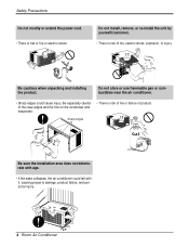
... with it, causing property damage, product failure, and personal injury. 4 Room Air Conditioner Do not store or use flammable gas or combustibles near the air conditioner. • Sharp edges could fall with age. • If the base collapses, the air conditioner could cause injury. Do not install, remove, or re-install the unit by yourself(customer). • There is risk or fire or electric shock.
... with it, causing property damage, product failure, and personal injury. 4 Room Air Conditioner Do not store or use flammable gas or combustibles near the air conditioner. • Sharp edges could fall with age. • If the base collapses, the air conditioner could cause injury. Do not install, remove, or re-install the unit by yourself(customer). • There is risk or fire or electric shock.
Service Manual
Page 5
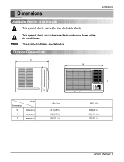
Outside Dimensions Dimensions D W H Dimension W H D Model mm(inch) mm(inch) mm(inch) REG-71A 471(18 9/16) 352(13 7/8) 525(20 11/16) Heat REG-123A 600(23 5/8) 380(14 31/22) 576(22 1/16) Service Manual 5 This symbol alerts you to the air conditioner. NOTICE This symbol indicates special notes. Dimensions Symbols Used in this Manual This symbol alerts you to hazards that could cause harm to the risk of electric shock.
Outside Dimensions Dimensions D W H Dimension W H D Model mm(inch) mm(inch) mm(inch) REG-71A 471(18 9/16) 352(13 7/8) 525(20 11/16) Heat REG-123A 600(23 5/8) 380(14 31/22) 576(22 1/16) Service Manual 5 This symbol alerts you to the air conditioner. NOTICE This symbol indicates special notes. Dimensions Symbols Used in this Manual This symbol alerts you to hazards that could cause harm to the risk of electric shock.
Service Manual
Page 6
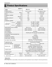
...RUNNING CURRENT (A) E.E.R (BTU/W.h) HEATING CAPACITY (Btu/h) INPUT (W) RUNNING CURRENT (A) OPERATING COOLING INDOOR(°C) OUTDOOR(°C) CONDITION HEATING INDOOR(°C) OUTDOOR(°C) REFRIGERANT (R-22) CHARGE EVAPORATOR CONDENSER FAN, INDOOR FAN, OUTDOOR FAN SPEEDS, FAN/COOLING/HEATING FAN MOTOR OPERATION CONTROL ROOM TEMP. CONTROL AIR DIRECTION CONTROL CONSTRUCTION ELECTRIC HEATER PROTECTOR COMPRESSOR FAN MOTOR ELECTRIC HEATER POWER CORD DRAIN SYSTEM NET WEIGHT OUTSIDE DIMENSION (W x H x D) (lbs/kg) (inch) (mm) REG-71A REG-123A 1Ø,115V, 60Hz...
...RUNNING CURRENT (A) E.E.R (BTU/W.h) HEATING CAPACITY (Btu/h) INPUT (W) RUNNING CURRENT (A) OPERATING COOLING INDOOR(°C) OUTDOOR(°C) CONDITION HEATING INDOOR(°C) OUTDOOR(°C) REFRIGERANT (R-22) CHARGE EVAPORATOR CONDENSER FAN, INDOOR FAN, OUTDOOR FAN SPEEDS, FAN/COOLING/HEATING FAN MOTOR OPERATION CONTROL ROOM TEMP. CONTROL AIR DIRECTION CONTROL CONSTRUCTION ELECTRIC HEATER PROTECTOR COMPRESSOR FAN MOTOR ELECTRIC HEATER POWER CORD DRAIN SYSTEM NET WEIGHT OUTSIDE DIMENSION (W x H x D) (lbs/kg) (inch) (mm) REG-71A REG-123A 1Ø,115V, 60Hz...
Service Manual
Page 7
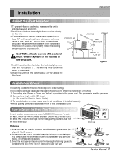
... air will help force condensed water to your particular DRAIN PAN DRAIN HOSE needs. (Drain hose is slightly lower than the front (about 30"~60" above the floor level. Fig. 3 Fig. 4 Service Manual 7 This will greatly reduce the cooling efficiency of the air conditioner. The following figures (by pushing down and away from the bottom about 1/2"). Press the drain pipe into the hole by considering the hole of the unit...
... air will help force condensed water to your particular DRAIN PAN DRAIN HOSE needs. (Drain hose is slightly lower than the front (about 30"~60" above the floor level. Fig. 3 Fig. 4 Service Manual 7 This will greatly reduce the cooling efficiency of the air conditioner. The following figures (by pushing down and away from the bottom about 1/2"). Press the drain pipe into the hole by considering the hole of the unit...
Service Manual
Page 8
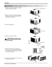
..., reinstall screw at the back. Remove EPS Material. 4. Push the grille in until it with a screw through the front grille. 8 Room Air Conditioner On/Off TIMER On/Off ESNAEVREGRY Fan Cool Heat MODE On/Off TIMER On/Off ESNAEVREGRY Fan Cool Heat MODE EPS Material Screw On/Off TIMER On/Off Fan Cool ESNAEVREGRY Heat MODE Power cord Screw On/Off TIMER On/Off Fan Cool Heat ESNAEVREGRY MODE Shipping screws 3. On/Off 2. Remove the screws that fasten the...
..., reinstall screw at the back. Remove EPS Material. 4. Push the grille in until it with a screw through the front grille. 8 Room Air Conditioner On/Off TIMER On/Off ESNAEVREGRY Fan Cool Heat MODE On/Off TIMER On/Off ESNAEVREGRY Fan Cool Heat MODE EPS Material Screw On/Off TIMER On/Off Fan Cool ESNAEVREGRY Heat MODE Power cord Screw On/Off TIMER On/Off Fan Cool Heat ESNAEVREGRY MODE Shipping screws 3. On/Off 2. Remove the screws that fasten the...
Service Manual
Page 9
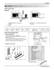
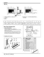
... OF PARTS Q'TY 1 FRAME CURTAIN 2 2 SILL SUPPORT 2 3 BOLT 2 4 NUT 2 5 SCREW(TYPE A) (10mm(2/5")) 16 6 SCREW(TYPE B) D5.1mm(0.2")/16mm(0.63") 3 7 SCREW(TYPE C)D4.1mm(0.17")/16mm(0.63") 5 8 FOAM-STRIP 1 9 FOAM-PE (920mm x 30mm x 2mm) 1 10 UPPER GUIDE 1 11 FOAM-PE (600mm x 25mm x 2mm) 1 12 FRAME GUIDE 2 13 WINDOW LOCKING BRACKET 1 14 DRAIN PIPE 1 s Top retainer bar is designed for installation in the product package. 10 Service Manual 9 GASKET...
... OF PARTS Q'TY 1 FRAME CURTAIN 2 2 SILL SUPPORT 2 3 BOLT 2 4 NUT 2 5 SCREW(TYPE A) (10mm(2/5")) 16 6 SCREW(TYPE B) D5.1mm(0.2")/16mm(0.63") 3 7 SCREW(TYPE C)D4.1mm(0.17")/16mm(0.63") 5 8 FOAM-STRIP 1 9 FOAM-PE (920mm x 30mm x 2mm) 1 10 UPPER GUIDE 1 11 FOAM-PE (600mm x 25mm x 2mm) 1 12 FRAME GUIDE 2 13 WINDOW LOCKING BRACKET 1 14 DRAIN PIPE 1 s Top retainer bar is designed for installation in the product package. 10 Service Manual 9 GASKET...
Service Manual
Page 10
... OF PARTS Q'TY 1 FRAME CURTAIN 2 2 SILL SUPPORT 2 3 BOLT 2 4 NUT 2 5 SCREW(TYPE A) (10mm(2/5")) 16 6 SCREW(TYPE B) D5.1mm(0.2")/16mm(0.63") 3 7 SCREW(TYPE C)D4.1mm(0.17")/16mm(0.63") 5 8 FOAM-STRIP 1 9 FOAM-PE (920mm x 30mm x 2mm) 1 10 UPPER GUIDE 1 11 FOAM-PE (600mm x 25mm x 2mm) 1 12 FRAME GUIDE 2 13 WINDOW LOCKING BRACKET 1 14 DRAIN PIPE 1 s Top retainer bar is designed for installation in the product package. 10 10 Room Air Conditioner...
... OF PARTS Q'TY 1 FRAME CURTAIN 2 2 SILL SUPPORT 2 3 BOLT 2 4 NUT 2 5 SCREW(TYPE A) (10mm(2/5")) 16 6 SCREW(TYPE B) D5.1mm(0.2")/16mm(0.63") 3 7 SCREW(TYPE C)D4.1mm(0.17")/16mm(0.63") 5 8 FOAM-STRIP 1 9 FOAM-PE (920mm x 30mm x 2mm) 1 10 UPPER GUIDE 1 11 FOAM-PE (600mm x 25mm x 2mm) 1 12 FRAME GUIDE 2 13 WINDOW LOCKING BRACKET 1 14 DRAIN PIPE 1 s Top retainer bar is designed for installation in the product package. 10 10 Room Air Conditioner...
Service Manual
Page 11
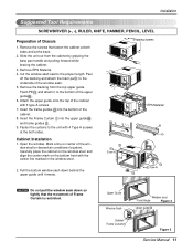
... cabinet. 8. Shipping screws On/Off TIMER On/Off ESNAEVREGRY Fan Cool Heat MODE On/Off TIMER On/Off Fan Cool ESNAEVREGRY Heat MODE On/Off TIMER On/Off ESNAEVREGRY Fan Cool Heat MODE 9 10 5 (Type A) 5 12 EPS Material 10 11 12 5 (Type A) NOTICE Do not pull the window sash down behind the upper guide until it to the underside of the window stool(or desired air conditioner location). Installation Suggested Tool Requirements SCREWDRIVER (+, -), RULER...
... cabinet. 8. Shipping screws On/Off TIMER On/Off ESNAEVREGRY Fan Cool Heat MODE On/Off TIMER On/Off Fan Cool ESNAEVREGRY Heat MODE On/Off TIMER On/Off ESNAEVREGRY Fan Cool Heat MODE 9 10 5 (Type A) 5 12 EPS Material 10 11 12 5 (Type A) NOTICE Do not pull the window sash down behind the upper guide until it to the underside of the window stool(or desired air conditioner location). Installation Suggested Tool Requirements SCREWDRIVER (+, -), RULER...

Service Manual
Page 13
.... Slide the unit into place. (See Fig. 11) 14. Attach the window Locking Bracket with a type A screw through the front grille.(See Fig. 12) Installation Screw(Type A) On/Off TIMER On/Off Fan Cool ESNAEVREGRY Heat MODE Power cord Screw(Type A) Figure 8 Foam-Strip 8 Figure 9 13 Figure 10 Figure 11 On/Off TIMER On/Off Fan Cool Heat ESNAEVREGRY MODE Figure 12 On/Off On/Off Fan Cool Heat TIMER ENERGY SAVER MODE Figure 13 Service Manual 13 Push...
.... Slide the unit into place. (See Fig. 11) 14. Attach the window Locking Bracket with a type A screw through the front grille.(See Fig. 12) Installation Screw(Type A) On/Off TIMER On/Off Fan Cool ESNAEVREGRY Heat MODE Power cord Screw(Type A) Figure 8 Foam-Strip 8 Figure 9 13 Figure 10 Figure 11 On/Off TIMER On/Off Fan Cool Heat ESNAEVREGRY MODE Figure 12 On/Off On/Off Fan Cool Heat TIMER ENERGY SAVER MODE Figure 13 Service Manual 13 Push...
Service Manual
Page 14
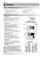
... compressor stops cooling. CAUTION: A slight heat odor may come from the unit when first switching to determine if cooling is set within a range of Controls • VENTILATION The ventilation lever must be set as follows. (Hi[ ] ➔ Low[ ] ➔ Hi[ ]....) 5. This button takes priority over . REMOCON SIGNAL RECEIVER 8. CLOSE 2 VENT OPEN REG-123A 33 6 44 5 4 REG-71A 7 Heat 3 62 51 REMOTE CONTROLLER REG-123A REG-71A Power 1 Power 1 Temp 5 Temp 5 Fan Speed 4 Fan Speed 4 Timer Mode Timer Mode 3 23 2 Energy Auto Saver Swing 7 87 Energy Saver 14 Room Air...
... compressor stops cooling. CAUTION: A slight heat odor may come from the unit when first switching to determine if cooling is set within a range of Controls • VENTILATION The ventilation lever must be set as follows. (Hi[ ] ➔ Low[ ] ➔ Hi[ ]....) 5. This button takes priority over . REMOCON SIGNAL RECEIVER 8. CLOSE 2 VENT OPEN REG-123A 33 6 44 5 4 REG-71A 7 Heat 3 62 51 REMOTE CONTROLLER REG-123A REG-71A Power 1 Power 1 Temp 5 Temp 5 Fan Speed 4 Fan Speed 4 Timer Mode Timer Mode 3 23 2 Energy Auto Saver Swing 7 87 Energy Saver 14 Room Air...
Service Manual
Page 15
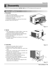
... disconnect the power cord. Remove two housings that fasten the control box cover. 4. Discharge the capacitor by referring to the removal procedure, above . Figure 14 On/Off TIMER On/Off ESNAEVREGRY Fan Cool Heat MODE 3. Remove the cabinet. (Refer to the circuit diagram found on the control box.) Figure 15 On/Off TIMER On/Off Fan Cool ESNAEVREGRY Heat MODE Figure 16 Service Manual 15 Remove the 2 screws that connect compressor wire and motor wire in this manual and...
... disconnect the power cord. Remove two housings that fasten the control box cover. 4. Discharge the capacitor by referring to the removal procedure, above . Figure 14 On/Off TIMER On/Off ESNAEVREGRY Fan Cool Heat MODE 3. Remove the cabinet. (Refer to the circuit diagram found on the control box.) Figure 15 On/Off TIMER On/Off Fan Cool ESNAEVREGRY Heat MODE Figure 16 Service Manual 15 Remove the 2 screws that connect compressor wire and motor wire in this manual and...
Service Manual
Page 16
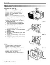
... cabinet. (Refer to section 3) 4. Remove the brace (Refer to the removal procedure. 16 Room Air Conditioner On/Off TIMER On/Off ESNAEVREGRY Fan Cool Heat MODE Figure 17 Figure 18 Figure 19 Figure 20 Remove the clamp that fasten the air guide from the base pan. 17. Re-install by referring to the left carefully. 5. Remove the front grille. (Refer to section 2) 3. Remove the 4 screws that secures...
... cabinet. (Refer to section 3) 4. Remove the brace (Refer to the removal procedure. 16 Room Air Conditioner On/Off TIMER On/Off ESNAEVREGRY Fan Cool Heat MODE Figure 17 Figure 18 Figure 19 Figure 20 Remove the clamp that fasten the air guide from the base pan. 17. Re-install by referring to the left carefully. 5. Remove the front grille. (Refer to section 2) 3. Remove the 4 screws that secures...
Service Manual
Page 18
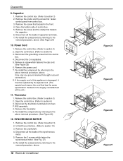
..., above . (See Figure 24) 10. Remove a screw which fasten the synchronous motor. (See Fig. 27) 6. Remove the power cord. 7. Remove the thermistor. 5. SYNCHRONOUS MOTOR 1. Re-install the components by referring to section 9) 3. Disconnect all the leads of capacitor terminals. 7. Re-install the components by referring to section 10) 3. Remove the control box. (Refer to the removal procedure, above . 18 Room Air Conditioner Figure 24 Figure 25 Figure...
..., above . (See Figure 24) 10. Remove a screw which fasten the synchronous motor. (See Fig. 27) 6. Remove the power cord. 7. Remove the thermistor. 5. SYNCHRONOUS MOTOR 1. Re-install the components by referring to section 9) 3. Disconnect all the leads of capacitor terminals. 7. Re-install the components by referring to section 10) 3. Remove the control box. (Refer to the removal procedure, above . 18 Room Air Conditioner Figure 24 Figure 25 Figure...
Service Manual
Page 20
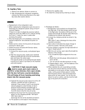
... Room Air Conditioner NOTICE - Replacement of the manifold and entire system. The vacuum pump is in figure 31B. Close valves A and B, and observe vacuum gauge for a while, and then test the leakage of the charge is now pulling through the access valve which you installed as the system was opened. 2) Connect the charging cylinder as a WATCO A-1) before venting...
... Room Air Conditioner NOTICE - Replacement of the manifold and entire system. The vacuum pump is in figure 31B. Close valves A and B, and observe vacuum gauge for a while, and then test the leakage of the charge is now pulling through the access valve which you installed as the system was opened. 2) Connect the charging cylinder as a WATCO A-1) before venting...
Service Manual
Page 24
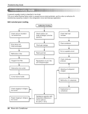
... at air outlet Correct above trouble Check outdoor coil (heat exchanger) & the fan operation. Repair clogging in refrigeration circuit. Check gas leakage. Check clogging in refrigeration circuit. 24 Room Air Conditioner Satisfactory operation with temperature difference of inlet & outlet air ; 44~50°F(7~10°C) Replacement of compressor. Dirty indoor coil (Heat exchanger) Malfunction of fan Clogged of refrigerant charged. Check inside gas pressure. Repair gas leak. Clean condenser. Adjusting of air filter. Ineffective Cooling Check cold air circulation...
... at air outlet Correct above trouble Check outdoor coil (heat exchanger) & the fan operation. Repair clogging in refrigeration circuit. Check gas leakage. Check clogging in refrigeration circuit. 24 Room Air Conditioner Satisfactory operation with temperature difference of inlet & outlet air ; 44~50°F(7~10°C) Replacement of compressor. Dirty indoor coil (Heat exchanger) Malfunction of fan Clogged of refrigerant charged. Check inside gas pressure. Repair gas leak. Clean condenser. Adjusting of air filter. Ineffective Cooling Check cold air circulation...
Service Manual
Page 25
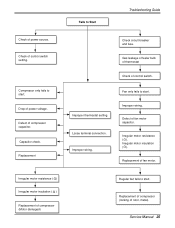
... of thermostat Check of fan motor capacitor. Irregular motor resistance ( ) Irregular motor insulation ( ) Replacement of compressor (Motor damaged) Regular but fails to start . Improper wiring. Drop of rotor, metal). Service Manual 25 Replacement of compressor (locking of power voltage. Check of fan motor. Fan only fails to start . Loose terminal connection. Irregular motor insulation ( ). Replacement Check circuit breaker and fuse. Improper wiring. Replacement of control switch setting. Capacitor check. Compressor only fails to Start Troubleshooting Guide...
... of thermostat Check of fan motor capacitor. Irregular motor resistance ( ) Irregular motor insulation ( ) Replacement of compressor (Motor damaged) Regular but fails to start . Improper wiring. Drop of rotor, metal). Service Manual 25 Replacement of compressor (locking of power voltage. Check of fan motor. Fan only fails to start . Loose terminal connection. Irregular motor insulation ( ). Replacement Check circuit breaker and fuse. Improper wiring. Replacement of control switch setting. Capacitor check. Compressor only fails to Start Troubleshooting Guide...
Service Manual
Page 26
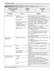
...% of the fan motor with mounting screw(s). Replace the switch if circuit is open . 26 Room Air Conditioner Troubleshooting Guide Room Air Conditioner Voltage Limits NAME PLATE RATING 208~230±10% 115±10% MINIMUM 187V 104V MAXIMUM 253V 126V COMPLAINT Fan motor will not run , but fan motor runs. Check voltage to wiring diagram for terminal identification. Replace switch if defective. Replace if shorted, open, or damaged. Check bearings. If none, check power supply cord. Tighten...
...% of the fan motor with mounting screw(s). Replace the switch if circuit is open . 26 Room Air Conditioner Troubleshooting Guide Room Air Conditioner Voltage Limits NAME PLATE RATING 208~230±10% 115±10% MINIMUM 187V 104V MAXIMUM 253V 126V COMPLAINT Fan motor will not run , but fan motor runs. Check voltage to wiring diagram for terminal identification. Replace switch if defective. Replace if shorted, open, or damaged. Check bearings. If none, check power supply cord. Tighten...
Service Manual
Page 27
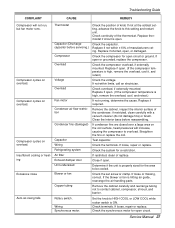
...motor for open circuit. Insufficient cooling or heating Excessive noise Thermostat Capacitor (Discharge capacitor before reassembling. Replace if shorted, open or grounded, replace the compressor. Remove the cabinet. Clean the interior base before servicing.) Compressor Overload Voltage Overload Fan motor Condenser air flow restriction Condenser fins (damaged) Capacitor Wiring Refrigerating system Air filter Exhaust damper door Unit undersized Blower or fan Check the position of knob If not at the coldest setting, advance the knob to this setting and restart unit. Check the set...
...motor for open circuit. Insufficient cooling or heating Excessive noise Thermostat Capacitor (Discharge capacitor before reassembling. Replace if shorted, open or grounded, replace the compressor. Remove the cabinet. Clean the interior base before servicing.) Compressor Overload Voltage Overload Fan motor Condenser air flow restriction Condenser fins (damaged) Capacitor Wiring Refrigerating system Air filter Exhaust damper door Unit undersized Blower or fan Check the position of knob If not at the coldest setting, advance the knob to this setting and restart unit. Check the set...
Service Manual
Page 30
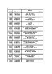
...W48602 352115-1 352115-2 137215 753000 Replacement Parts List DESCRIPTION AAN32956302 REG-123A DESCRIPTION BASE ASSY,SINGLE REMARK R 3091A10032V CABINET ASSY, SINGLE R 3531A20020E GRILLE ASSY ,FRONT R 3530AR1634A GRILLE ASSY , INLET R 3550AR7032A COVER R 5990AR6191K LOUVER HORIZONTAL R 4758AR7308D LOUVER VERTICAL R 4810AR7029A BRACE R 4998AR1496A SHROUD R 5231AR1152A FILTER(MECH), A/C R MDD37823803 ESCUTCHEON R 4995A23005Q CONTROL BOX ASSEMBLY, SINGLE R 6411A20056Q POWER CORD ASSEMBLY R 6323A20003S THERMISTOR ASSEMBLY R 6871A20611U PWB(PCB) ASSEMBLY...
...W48602 352115-1 352115-2 137215 753000 Replacement Parts List DESCRIPTION AAN32956302 REG-123A DESCRIPTION BASE ASSY,SINGLE REMARK R 3091A10032V CABINET ASSY, SINGLE R 3531A20020E GRILLE ASSY ,FRONT R 3530AR1634A GRILLE ASSY , INLET R 3550AR7032A COVER R 5990AR6191K LOUVER HORIZONTAL R 4758AR7308D LOUVER VERTICAL R 4810AR7029A BRACE R 4998AR1496A SHROUD R 5231AR1152A FILTER(MECH), A/C R MDD37823803 ESCUTCHEON R 4995A23005Q CONTROL BOX ASSEMBLY, SINGLE R 6411A20056Q POWER CORD ASSEMBLY R 6323A20003S THERMISTOR ASSEMBLY R 6871A20611U PWB(PCB) ASSEMBLY...


