Service Manual
Page 2
... Install(Models with Installation Kit 9 Suggested Tool Requirements ...11 Operation ...14 Features ...14 Control Locations Function of Controls ...14 Disassembly ...15 Mechanical Parts...15 Air Handling Parts ...16 Electrical Parts ...17 Refrigerating Cycle...19 Schematic Diagram...22 Wiring Diagram...22 Troubleshooting Guide ...23 Piping System ...23 Troubleshooting Guide ...24 Room Air Conditioner Voltage...
... Install(Models with Installation Kit 9 Suggested Tool Requirements ...11 Operation ...14 Features ...14 Control Locations Function of Controls ...14 Disassembly ...15 Mechanical Parts...15 Air Handling Parts ...16 Electrical Parts ...17 Refrigerating Cycle...19 Schematic Diagram...22 Wiring Diagram...22 Troubleshooting Guide ...23 Piping System ...23 Troubleshooting Guide ...24 Room Air Conditioner Voltage...
Service Manual
Page 9
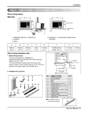
NAME OF PARTS Q'TY 1 FRAME CURTAIN 2 2 SILL SUPPORT 2 3 BOLT 2 4 NUT 2 5 SCREW(TYPE A) (10mm(2/5")) 16 6 SCREW(TYPE B) D5.1mm(0.2")/16mm(0.63") 3 7 SCREW(TYPE C)D4.1mm(0.17")/16mm(0.63") 5 8 FOAM-... 12 14 235/8" min (Without frame curtain) NO. WALL 4. Window Requirements This unit is in standard double hung windows with Installaion Kit) When Using Gasket REG-123A A 1 A 2 2 B H 3 4 DE F RIGHT SIDE B HORIZONTAL LINE I 625mm (245/8") 392mm (157/16") 280mm (111/32") 30mm (11/16") 0~25mm (0~1") OVER 420mm (OVER 1617/32") 5~10mm -5~5mm (3/16...
NAME OF PARTS Q'TY 1 FRAME CURTAIN 2 2 SILL SUPPORT 2 3 BOLT 2 4 NUT 2 5 SCREW(TYPE A) (10mm(2/5")) 16 6 SCREW(TYPE B) D5.1mm(0.2")/16mm(0.63") 3 7 SCREW(TYPE C)D4.1mm(0.17")/16mm(0.63") 5 8 FOAM-... 12 14 235/8" min (Without frame curtain) NO. WALL 4. Window Requirements This unit is in standard double hung windows with Installaion Kit) When Using Gasket REG-123A A 1 A 2 2 B H 3 4 DE F RIGHT SIDE B HORIZONTAL LINE I 625mm (245/8") 392mm (157/16") 280mm (111/32") 30mm (11/16") 0~25mm (0~1") OVER 420mm (OVER 1617/32") 5~10mm -5~5mm (3/16...
Service Manual
Page 10
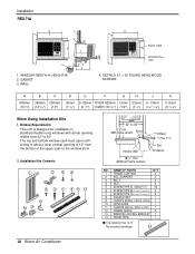
... (10") D E F G H 30mm 0~25mm OVER 420mm 12mm 32mm (11/16") (0~1") (OVER 1617/32") (1/2") (11/4") J 5~10mm (3/16"~3/8") K 0~5mm (0~3/16") When Using Installation Kits 1. NAME OF PARTS Q'TY 1 FRAME CURTAIN 2 2 SILL SUPPORT 2 3 BOLT 2 4 NUT 2 5 SCREW(TYPE A) (10mm(2/5")) 16 6 SCREW(TYPE B) D5.1mm(0.2")/16mm(0.63") 3 7 SCREW(TYPE C)D4.1mm(0.17")/16mm(0.63")... a clear vertical opening widths from the bottom of 15" from 22" to 11/4" Sill Exterior NO. GASKET 3. Installation REG-71A A 2 On/Off On/Off Fan Cool Heat TIMER ENERGY SAVER MODE 1 2 G B C 4 1.
... (10") D E F G H 30mm 0~25mm OVER 420mm 12mm 32mm (11/16") (0~1") (OVER 1617/32") (1/2") (11/4") J 5~10mm (3/16"~3/8") K 0~5mm (0~3/16") When Using Installation Kits 1. NAME OF PARTS Q'TY 1 FRAME CURTAIN 2 2 SILL SUPPORT 2 3 BOLT 2 4 NUT 2 5 SCREW(TYPE A) (10mm(2/5")) 16 6 SCREW(TYPE B) D5.1mm(0.2")/16mm(0.63") 3 7 SCREW(TYPE C)D4.1mm(0.17")/16mm(0.63")... a clear vertical opening widths from the bottom of 15" from 22" to 11/4" Sill Exterior NO. GASKET 3. Installation REG-71A A 2 On/Off On/Off Fan Cool Heat TIMER ENERGY SAVER MODE 1 2 G B C 4 1.
Service Manual
Page 12
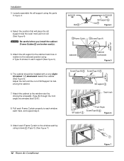
... Screw(Type B) 6 Figure 6 9. Attach the sill support to the cabinet track hole in Figure 4. 4. Pull each Frame Curtain properly to the selected position using the parts in relation to each support (See Figure 5). 6. Adjust the bolt and the nut of Sill Support for balancing the cabinet. 7. Installation 3.
... Screw(Type B) 6 Figure 6 9. Attach the sill support to the cabinet track hole in Figure 4. 4. Pull each Frame Curtain properly to the selected position using the parts in relation to each support (See Figure 5). 6. Adjust the bolt and the nut of Sill Support for balancing the cabinet. 7. Installation 3.
Service Manual
Page 15
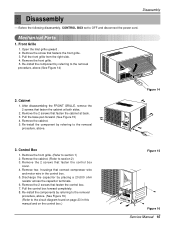
... 16) (Refer to section 2) 3. Pull the base pan forward. (See Figure 15) 4. Figure 14 On/Off TIMER On/Off ESNAEVREGRY Fan Cool Heat MODE 3. Mechanical Parts 1. Remove the front grille. (Refer to the removal procedure, above . Remove the 2 screws that fastens the front grille. 3. Remove the screw that fasten the control...
... 16) (Refer to section 2) 3. Pull the base pan forward. (See Figure 15) 4. Figure 14 On/Off TIMER On/Off ESNAEVREGRY Fan Cool Heat MODE 3. Mechanical Parts 1. Remove the front grille. (Refer to the removal procedure, above . Remove the 2 screws that fastens the front grille. 3. Remove the screw that fasten the control...
Service Manual
Page 16
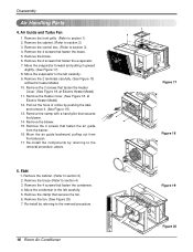
.../Off ESNAEVREGRY Fan Cool Heat MODE Figure 17 Figure 18 Figure 19 Figure 20 FAN 1. Move the condenser to the left carefully. 5. Disassembly Air Handling Parts 4. Air Guide and Turbo Fan 1.
.../Off ESNAEVREGRY Fan Cool Heat MODE Figure 17 Figure 18 Figure 19 Figure 20 FAN 1. Move the condenser to the left carefully. 5. Disassembly Air Handling Parts 4. Air Guide and Turbo Fan 1.
Service Manual
Page 17
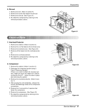
... a Watco A-1) before venting the Freon™.. Remove all the leads from the overload protec- If there is no valve to the removal procedure, above . Electrical Parts 7. Remove the terminal cover. (See Figure 22) 4. Remove the nut that fastens the terminal cover. 3. 6.
... a Watco A-1) before venting the Freon™.. Remove all the leads from the overload protec- If there is no valve to the removal procedure, above . Electrical Parts 7. Remove the terminal cover. (See Figure 22) 4. Remove the nut that fastens the terminal cover. 3. 6.
Service Manual
Page 27
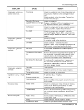
.... Check the terminals. If loose or missing, correct. Check overload, if externally mounted. Determine if the unit is hitting air guide, rearrange the air handling parts. Check the synchronous motor for a restriction. Test capacitor. Check the capacitor. Close if open circuit. Compressor cycles on overload. Set the knob to HIGH COOL...
.... Check the terminals. If loose or missing, correct. Check overload, if externally mounted. Determine if the unit is hitting air guide, rearrange the air handling parts. Check the synchronous motor for a restriction. Test capacitor. Check the capacitor. Close if open circuit. Compressor cycles on overload. Set the knob to HIGH COOL...
Service Manual
Page 29
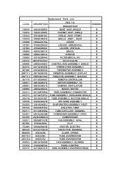
...-2 267110 346811 349001 349600 352111 352113 35211A 749750 354210 550140 552111 554031 554160 559011 567502 753000 W0CZZ W48602 352115-1 352115-2 359012 137215 352115 Replacement Parts List DESCRIPTION 3041A30005V REG-71A DESCRIPTION BASE ASSY,SINGLE REMARK R 3091A10069F CABINET ASSY, SINGLE R 3531A29018C GRILLE ASSY ,FRONT R 3530A10027A GRILLE ASSY , INLET R 3550A20115A COVER R 4758A20002G LOUVER HORIZONTAL...
...-2 267110 346811 349001 349600 352111 352113 35211A 749750 354210 550140 552111 554031 554160 559011 567502 753000 W0CZZ W48602 352115-1 352115-2 359012 137215 352115 Replacement Parts List DESCRIPTION 3041A30005V REG-71A DESCRIPTION BASE ASSY,SINGLE REMARK R 3091A10069F CABINET ASSY, SINGLE R 3531A29018C GRILLE ASSY ,FRONT R 3530A10027A GRILLE ASSY , INLET R 3550A20115A COVER R 4758A20002G LOUVER HORIZONTAL...
Service Manual
Page 30
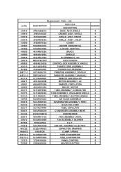
...-2 267110 346811 349001 349600 352111 352113 35211A 749750 354210 550140 552111 554031 554160 559011 359012 567502 753010 W0CZZ W48602 352115-1 352115-2 137215 753000 Replacement Parts List DESCRIPTION AAN32956302 REG-123A DESCRIPTION BASE ASSY,SINGLE REMARK R 3091A10032V CABINET ASSY, SINGLE R 3531A20020E GRILLE ASSY ,FRONT R 3530AR1634A GRILLE ASSY , INLET R 3550AR7032A COVER R 5990AR6191K LOUVER HORIZONTAL R 4758AR7308D...
...-2 267110 346811 349001 349600 352111 352113 35211A 749750 354210 550140 552111 554031 554160 559011 359012 567502 753010 W0CZZ W48602 352115-1 352115-2 137215 753000 Replacement Parts List DESCRIPTION AAN32956302 REG-123A DESCRIPTION BASE ASSY,SINGLE REMARK R 3091A10032V CABINET ASSY, SINGLE R 3531A20020E GRILLE ASSY ,FRONT R 3530AR1634A GRILLE ASSY , INLET R 3550AR7032A COVER R 5990AR6191K LOUVER HORIZONTAL R 4758AR7308D...


