Service Manual
Page 2
... and Evacuation ...36 Checking method ...36 Evacuation...37 Charging ...38 Test Running ...39 Operation ...40 Function of control...40 Function of Indoor Unit ...45 Function of Outdoor Unit ...47 Remote Control Operation ...48 Disassembly ...49 Indoor Unit...49 Schematic Diagram...54 Electronic Control Device ...54 Wiring Diagram...58 Components Locations...59 Troubleshooting Guide ...64 Refrigeration Cycle...
... and Evacuation ...36 Checking method ...36 Evacuation...37 Charging ...38 Test Running ...39 Operation ...40 Function of control...40 Function of Indoor Unit ...45 Function of Outdoor Unit ...47 Remote Control Operation ...48 Disassembly ...49 Indoor Unit...49 Schematic Diagram...54 Electronic Control Device ...54 Wiring Diagram...58 Components Locations...59 Troubleshooting Guide ...64 Refrigeration Cycle...
Service Manual
Page 10
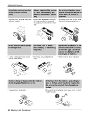
... the batteries have leaked. • The chemicals in the remote control with clean water. Safety Precautions Do not step on or put anyting on the product. (outdoor units) Always insert the filter securely. Do not insert ... damage. • There are sharp and moving parts that could cause burns or other objects through the air inlet or outlet while the product is operated. • There is not sanitary and could cause • Be careful and avoid personal serious health issues. when cleaning or maintaining the product. • It...
... the batteries have leaked. • The chemicals in the remote control with clean water. Safety Precautions Do not step on or put anyting on the product. (outdoor units) Always insert the filter securely. Do not insert ... damage. • There are sharp and moving parts that could cause burns or other objects through the air inlet or outlet while the product is operated. • There is not sanitary and could cause • Be careful and avoid personal serious health issues. when cleaning or maintaining the product. • It...
Service Manual
Page 39
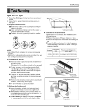
... air Discharge temperature Intake temperature Discharge temperature Service Manual 39 Bolt Tubing connection 4) Evaluation of battery are fully open. 1) Prepare remote controller Remove the battery cover by pushing it leads to the hose, secure the unit with an anti-vibration rubber. Do not use... from the remote controller if the sys- Check that the gas and liquid side service valves are installed correctly. Insert new batteries making sure that all tubing and wiring have been properly connected. 2. Measure the pressure of compressor. If heating operation is conveyed ...
... air Discharge temperature Intake temperature Discharge temperature Service Manual 39 Bolt Tubing connection 4) Evaluation of battery are fully open. 1) Prepare remote controller Remove the battery cover by pushing it leads to the hose, secure the unit with an anti-vibration rubber. Do not use... from the remote controller if the sys- Check that the gas and liquid side service valves are installed correctly. Insert new batteries making sure that all tubing and wiring have been properly connected. 2. Measure the pressure of compressor. If heating operation is conveyed ...

Service Manual
Page 40
...the setting temp, they start during heating mode operation or while in defrost control I Soft Dry Operation Mode • When the dehumidification operation input by the remote control. MAIN UNIT FUNCTION • DISPLAY Operation Indicator • On while in appliance operation, off while in appliance pause • ....1°F) • While in timer mode (on/off), off fan operates at low speed regardless of control 1. While compressor is off when timer mode is automatically set by the remote control is received, the intake air temperature is detected and the setting temp...
...the setting temp, they start during heating mode operation or while in defrost control I Soft Dry Operation Mode • When the dehumidification operation input by the remote control. MAIN UNIT FUNCTION • DISPLAY Operation Indicator • On while in appliance operation, off while in appliance pause • ....1°F) • While in timer mode (on/off), off fan operates at low speed regardless of control 1. While compressor is off when timer mode is automatically set by the remote control is received, the intake air temperature is detected and the setting temp...
Service Manual
Page 42
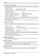
Operation 2) Fuzzy Operation for Dehumidification • According to the intake air temp at that time. 26°C(78.8°F) ≤ Intake Air Temp ➲ 25°C(77°F) ... Compressor ON Temp ➲ Setting Temp + 0.5°C(32.9°F) Compressor OFF Temp ➲ Setting Temp+0.5°C(32.9°F) • At the beginning of Fuzzy mode operation, the setting temperature is automatically selected according to the setting temperature selected by Fuzzy rule, when the intake air temp is 0.5°C(32.9°F) or...
Operation 2) Fuzzy Operation for Dehumidification • According to the intake air temp at that time. 26°C(78.8°F) ≤ Intake Air Temp ➲ 25°C(77°F) ... Compressor ON Temp ➲ Setting Temp + 0.5°C(32.9°F) Compressor OFF Temp ➲ Setting Temp+0.5°C(32.9°F) • At the beginning of Fuzzy mode operation, the setting temperature is automatically selected according to the setting temperature selected by Fuzzy rule, when the intake air temp is 0.5°C(32.9°F) or...

Service Manual
Page 43
...When the sleep time is reached after is input by the remote control while in appliance operation, the operation of the airflow mode is operated for 30 min at cooling mode operation. • In the Jet Cool mode operation, the room temperature is controlled to the set by the timer, the pause continues. ...the on the memory. randomly by the remote control, the on/off-timer operation is kept on the memory and the appliance automatically operates in heating mode or Fuzzy operation, the Jet Cool key cannot be input. • While in cooling mode operation, 30 min later since the start ...
...When the sleep time is reached after is input by the remote control while in appliance operation, the operation of the airflow mode is operated for 30 min at cooling mode operation. • In the Jet Cool mode operation, the room temperature is controlled to the set by the timer, the pause continues. ...the on the memory. randomly by the remote control, the on/off-timer operation is kept on the memory and the appliance automatically operates in heating mode or Fuzzy operation, the Jet Cool key cannot be input. • While in cooling mode operation, 30 min later since the start ...

Service Manual
Page 44
... for around 15 sec and then the opera- Operation I Forced Operation • To operate the appliance by force in case that the remote control is lost, the forced operation selection switch is on the main unit of the appliance to operate the appliance in the standard conditions. • ...• When the slide switch position is switched from the forced operation position to the Auto Restarting position or the remote control position, the forced operation is canceled and the appliance stops operating. • In the forced operation mode, the indoor fan is set according to the intake air ...
... for around 15 sec and then the opera- Operation I Forced Operation • To operate the appliance by force in case that the remote control is lost, the forced operation selection switch is on the main unit of the appliance to operate the appliance in the standard conditions. • ...• When the slide switch position is switched from the forced operation position to the Auto Restarting position or the remote control position, the forced operation is canceled and the appliance stops operating. • In the forced operation mode, the indoor fan is set according to the intake air ...

Service Manual
Page 45
... : The function illustrates its dynamic mode by Remote controller Sensing the Room Temperature • Room temperature sensor. (THERMISTOR) Room temperature control • Maintains the room temperature in accordance with the Setting Temp. Natural Air Control by CHAOS Logic • The fan is switched to intermittent or irregular operation • The fan speed is automatically switched...
... : The function illustrates its dynamic mode by Remote controller Sensing the Room Temperature • Room temperature sensor. (THERMISTOR) Room temperature control • Maintains the room temperature in accordance with the Setting Temp. Natural Air Control by CHAOS Logic • The fan is switched to intermittent or irregular operation • The fan speed is automatically switched...
Service Manual
Page 46
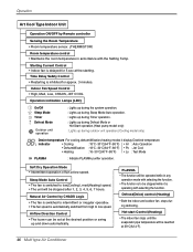
.../Off Sleep Mode Timer Defrost Mode Outdoor unit operation : Lights up during the system operation. : Lights up during Sleep Mode Auto operation. : Lights up during Timer operation. : Lights up during Defrost Mode or Hot Start operation.(Heat pump model only) : Lights up and down automatically. Natural Air Control by Remote controller Sensing the Room Temperature • Room temperature...
.../Off Sleep Mode Timer Defrost Mode Outdoor unit operation : Lights up during the system operation. : Lights up during Sleep Mode Auto operation. : Lights up during Timer operation. : Lights up during Defrost Mode or Hot Start operation.(Heat pump model only) : Lights up and down automatically. Natural Air Control by Remote controller Sensing the Room Temperature • Room temperature...
Service Manual
Page 48
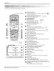
Operation Remote Control Operation The Remote Controller transmits the signals to set Auto Clean mode. 17 ˚C TO ˚F SWITCHING BUTTON Used to switch temperature reading from Centigrade to Fahrenheit. 18 HORIZONTAL AIRFLOW DIRECTION CONTROL BUTTON (NOT ON ALL MODELS) Used to the system. Signal transmitter 5 1 6 3 4 2 10 CANCEL 7 9 ON OFF SET 11 AUTO CLEAN 16 8 12 °C/°...
Operation Remote Control Operation The Remote Controller transmits the signals to set Auto Clean mode. 17 ˚C TO ˚F SWITCHING BUTTON Used to switch temperature reading from Centigrade to Fahrenheit. 18 HORIZONTAL AIRFLOW DIRECTION CONTROL BUTTON (NOT ON ALL MODELS) Used to the system. Signal transmitter 5 1 6 3 4 2 10 CANCEL 7 9 ON OFF SET 11 AUTO CLEAN 16 8 12 °C/°...

Service Manual
Page 68
...been stopped, the compressor does not operate owing to the low speed as force.) Caused by the remote controller. At this point the wind speed is not controlled by a low speed. Check the contact of CN-DISP 1 connector When the detect switch (double key) inside the remote controller door is fault, it is set... CN1 DC +5V Check the Display PWB Ass'y • Check receiver ass'y 68 Multi type Air Conditioner Caused by other parts except the remote controller When the mark ( ) is driven by the remote controller. (When operated in LCD screen, replace battery. Turn on main power.
...been stopped, the compressor does not operate owing to the low speed as force.) Caused by the remote controller. At this point the wind speed is not controlled by a low speed. Check the contact of CN-DISP 1 connector When the detect switch (double key) inside the remote controller door is fault, it is set... CN1 DC +5V Check the Display PWB Ass'y • Check receiver ass'y 68 Multi type Air Conditioner Caused by other parts except the remote controller When the mark ( ) is driven by the remote controller. (When operated in LCD screen, replace battery. Turn on main power.
Service Manual
Page 69
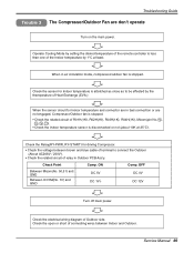
... relay in Outdoor PCB Ass'y. Check Point Between Micom(No. 50,51) and GND Between IC01M(No. 10) and GND Comp. Operate Cooling Mode by setting the disired temperature of the remote controller is less than one of R01H(1K), R02H(1K), R03H(1K), R04H(1K), Micom(pin No. 74 , 75 , 76 , 77... Outdoor side. OFF DC 0V DC 12V Turn off main power. ON DC 5V DC 1V↓ Comp. When in bad connection or are don't operate Turn on the main power. Check the sensor for Indoor temperature is stopped. Service Manual 69 Troubleshooting Guide Trouble 3 The Compressor/Outdoor Fan are not...
... relay in Outdoor PCB Ass'y. Check Point Between Micom(No. 50,51) and GND Between IC01M(No. 10) and GND Comp. Operate Cooling Mode by setting the disired temperature of the remote controller is less than one of R01H(1K), R02H(1K), R03H(1K), R04H(1K), Micom(pin No. 74 , 75 , 76 , 77... Outdoor side. OFF DC 0V DC 12V Turn off main power. ON DC 5V DC 1V↓ Comp. When in bad connection or are don't operate Turn on the main power. Check the sensor for Indoor temperature is stopped. Service Manual 69 Troubleshooting Guide Trouble 3 The Compressor/Outdoor Fan are not...


