Service Manual
Page 2
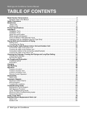
... this Manual ...4 Safety Precautions...5 Dimensions...11 Indoor Unit...11 Outdoor Unit ...12 Product Specifications ...13 Installation ...15 Installation Parts...15 Installation Tools...15 Select the best location ...16 Piping length and elevation ...17 Fixing Installation Plate(Standart Type 18 ... Refrigeration Cycle Diagram ...64 Self-diagnosis Function ...65 Cycle Troubleshooting Guide...66 Electronic Parts Troubleshooting Guide 67 General Information...72 2-way, 3-way Valve ...78 Exploded View & Replacement Parts List 82 Indoor Unit ...82 Outdoor Unit ...86 2 Multi type Air Conditioner
... this Manual ...4 Safety Precautions...5 Dimensions...11 Indoor Unit...11 Outdoor Unit ...12 Product Specifications ...13 Installation ...15 Installation Parts...15 Installation Tools...15 Select the best location ...16 Piping length and elevation ...17 Fixing Installation Plate(Standart Type 18 ... Refrigeration Cycle Diagram ...64 Self-diagnosis Function ...65 Cycle Troubleshooting Guide...66 Electronic Parts Troubleshooting Guide 67 General Information...72 2-way, 3-way Valve ...78 Exploded View & Replacement Parts List 82 Indoor Unit ...82 Outdoor Unit ...86 2 Multi type Air Conditioner
Service Manual
Page 7
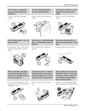
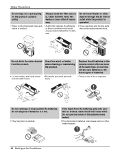
... or off or disconnect the power supply cable. If possible, remove the product from product. Service Manual 7 Do not allow water to run into electric parts. • It may cause There is risk of fire, failure of fire and electric shock. Turn the breaker off . time. • There is risk of...
... or off or disconnect the power supply cable. If possible, remove the product from product. Service Manual 7 Do not allow water to run into electric parts. • It may cause There is risk of fire, failure of fire and electric shock. Turn the breaker off . time. • There is risk of...
Service Manual
Page 9
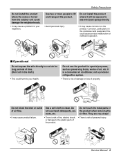
...condenser and evaporator fins, could cause product malfunction or inefficient operation. Use a soft cloth to lift and transport the product. Do not touch the metal parts of air flow. They are very sharp! • It may cause product failure. • There is risk of time. (Don't sit in ... the neighborhoods. • It may cause a problem for your health. Do not install the product where it will be exposed to the plastic parts of the product. • There is risk of damage or loss of personal injury. Corrosion, particularly on the product. Wax Thinner Service Manual ...
...condenser and evaporator fins, could cause product malfunction or inefficient operation. Use a soft cloth to lift and transport the product. Do not touch the metal parts of air flow. They are very sharp! • It may cause product failure. • There is risk of time. (Don't sit in ... the neighborhoods. • It may cause a problem for your health. Do not install the product where it will be exposed to the plastic parts of the product. • There is risk of damage or loss of personal injury. Corrosion, particularly on the product. Wax Thinner Service Manual ...
Service Manual
Page 10
... mix old and new batteries or different types of the air conditioner and could cause product malfunction or damage. • There are sharp and moving parts that could cause burns or other health hazards. 10 Multi type Air Conditioner Do not dispose of fire or explosion Do not recharge or disassemble...
... mix old and new batteries or different types of the air conditioner and could cause product malfunction or damage. • There are sharp and moving parts that could cause burns or other health hazards. 10 Multi type Air Conditioner Do not dispose of fire or explosion Do not recharge or disassemble...
Service Manual
Page 13
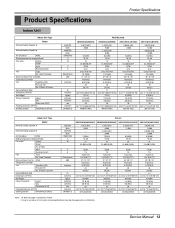
... & Column Dehumidification Rate Dimensions (W*H*D) Net Weight Piping Connection Liquid Gas Drain hose (ID Ø) Packing Dimension (W*H*D) Stuffing Quantity With(Without) S/Parts kcal/h(W) Btu/h kcal/h(W) Btu/h CMM(CFM) °C W Artcool AMNC093APM0(LMAN090CNS) AMNH093APM0(LMAN090HNS) AMNC123APM0(LMAN120CNS) AMNH123APM0(LMAN120HNS) 2,267(2,637)... - 35.2*11.1*6.5(895*282*165) 9.5(20.9) 1/4 (6.35) 3/8 (9.52) 20 38.3*9.1*14.6(973*231*372) 353/719 (792) AMNH123DEA0 (LMN120HE) 3,023(3,516) 12,000 3,023(3,516) 12,000 9.4(332) 16~30 15 DL-88430LGIF DC36 0.15 Cross Flow Fan 1/3.74(95) 36...
... & Column Dehumidification Rate Dimensions (W*H*D) Net Weight Piping Connection Liquid Gas Drain hose (ID Ø) Packing Dimension (W*H*D) Stuffing Quantity With(Without) S/Parts kcal/h(W) Btu/h kcal/h(W) Btu/h CMM(CFM) °C W Artcool AMNC093APM0(LMAN090CNS) AMNH093APM0(LMAN090HNS) AMNC123APM0(LMAN120CNS) AMNH123APM0(LMAN120HNS) 2,267(2,637)... - 35.2*11.1*6.5(895*282*165) 9.5(20.9) 1/4 (6.35) 3/8 (9.52) 20 38.3*9.1*14.6(973*231*372) 353/719 (792) AMNH123DEA0 (LMN120HE) 3,023(3,516) 12,000 3,023(3,516) 12,000 9.4(332) 16~30 15 DL-88430LGIF DC36 0.15 Cross Flow Fan 1/3.74(95) 36...
Service Manual
Page 15
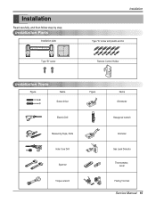
Installation Read carefully, and then follow step by step. Installation Parts Installation plate Type "B" screw Installation Type "A" screw and plastic anchor Remote Control Holder Installation Tools Figure Name Screw driver Electric Drill Measuring Tape, Knife Hole Core Drill Spanner Torque wrench Figure Name Ohmmeter Hexagonal wrench Ammeter Gas Leak Detector Thermometer, Level Flaring Tool Set Service Manual 15
Installation Read carefully, and then follow step by step. Installation Parts Installation plate Type "B" screw Installation Type "A" screw and plastic anchor Remote Control Holder Installation Tools Figure Name Screw driver Electric Drill Measuring Tape, Knife Hole Core Drill Spanner Torque wrench Figure Name Ohmmeter Hexagonal wrench Ammeter Gas Leak Detector Thermometer, Level Flaring Tool Set Service Manual 15
Service Manual
Page 19
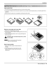
...hear sound this panel came out, In this panel a bit, and separate connecting wire with product. Pipe hole Adhesive Only one desiring direction Connecting part Drain hose rubber cap Service Manual 19 CAUTION: After removing the pipe hole, cut the burr for safety. The moment of lifting the both lower... parts of drain pan, and join drain hose and connecting hose. After pull down this time panel front is separated. 3. Remove the rubber stopple ...
...hear sound this panel came out, In this panel a bit, and separate connecting wire with product. Pipe hole Adhesive Only one desiring direction Connecting part Drain hose rubber cap Service Manual 19 CAUTION: After removing the pipe hole, cut the burr for safety. The moment of lifting the both lower... parts of drain pan, and join drain hose and connecting hose. After pull down this time panel front is separated. 3. Remove the rubber stopple ...
Service Manual
Page 20
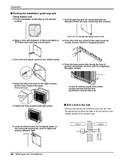
Drill the piercing part for hanging product) 10mm INSTALLATION GU 9. INSTAIIATION GUIDE MAP 3. In case of piercing rear surface) 2. Look at suited horizon by horizontal meter on the horizontal ... two points of product with the hole slightly slanted to No. 5 on the desired surface. INSTALLATION GUIDE MAP 7. Drive the lower parts after facing the hole of the upper parts by adhesive tape. Hang the hole of product at either the right or the left with plastic anchors, and fix completely the...
Drill the piercing part for hanging product) 10mm INSTALLATION GU 9. INSTAIIATION GUIDE MAP 3. In case of piercing rear surface) 2. Look at suited horizon by horizontal meter on the horizontal ... two points of product with the hole slightly slanted to No. 5 on the desired surface. INSTALLATION GUIDE MAP 7. Drive the lower parts after facing the hole of the upper parts by adhesive tape. Hang the hole of product at either the right or the left with plastic anchors, and fix completely the...
Service Manual
Page 26
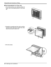
Flaring Work and Connection of panel front Panel Front Connector 3. Assemble connecting lead wire with controller and first fix the upper part of panel front, then match the lower part of Piping I Panel Assembly(Art Cool Type only) 1. Drive two screws. 26 Multi type Air Conditioner First, Check the side cover assembly exactly, Fix power cord in the bottom groove of cover side left. 2.
Flaring Work and Connection of panel front Panel Front Connector 3. Assemble connecting lead wire with controller and first fix the upper part of panel front, then match the lower part of Piping I Panel Assembly(Art Cool Type only) 1. Drive two screws. 26 Multi type Air Conditioner First, Check the side cover assembly exactly, Fix power cord in the bottom groove of cover side left. 2.
Service Manual
Page 31
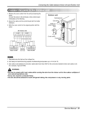
... the cover control from the indoor unit to the outdoor unit(size of withstanding temperature up to touch refrigerant tubing, the compressor or any moving parts. Outdoor unit Terminal block Over 5mm Holder for the connection between Indoor Unit and Outdoor Unit Connect the cable to the Outdoor unit. 1. Use heat...
... the cover control from the indoor unit to the outdoor unit(size of withstanding temperature up to touch refrigerant tubing, the compressor or any moving parts. Outdoor unit Terminal block Over 5mm Holder for the connection between Indoor Unit and Outdoor Unit Connect the cable to the Outdoor unit. 1. Use heat...
Service Manual
Page 35
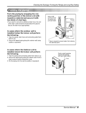
... In cases where the outdoor unit is required to prevent water from down to up . 2. Tape the piping and connecting cable from entering into electrical parts. Secure the taped piping along the exterior wall using saddle or equivalent. Secure the drain hose appropriately. In cases where the Outdoor unit is installed...
... In cases where the outdoor unit is required to prevent water from down to up . 2. Tape the piping and connecting cable from entering into electrical parts. Secure the taped piping along the exterior wall using saddle or equivalent. Secure the drain hose appropriately. In cases where the Outdoor unit is installed...
Service Manual
Page 36
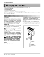
Check that each indoor unit connection set, separately. Usually, the cylinder is found to corrosion of parts in the refrigeration system. When the system pressure is reduced to this stage. Cooling(or heating) efficiency drops. 4. Leakage test • Connect the manifold valve(...
Check that each indoor unit connection set, separately. Usually, the cylinder is found to corrosion of parts in the refrigeration system. When the system pressure is reduced to this stage. Cooling(or heating) efficiency drops. 4. Leakage test • Connect the manifold valve(...
Service Manual
Page 52
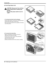
... this panel a bit, separate connecting wire with product. 2. Be sure the power switch is set to disconnect the wires from PWB. - Lift the both lower parts of panel front. - Remove securing screws. - Disassembly Art Cool Type Indoor Unit CAUTION: Disconnect the unit from the chassis carefully. To remove the Control Box...
... this panel a bit, separate connecting wire with product. 2. Be sure the power switch is set to disconnect the wires from PWB. - Lift the both lower parts of panel front. - Remove securing screws. - Disassembly Art Cool Type Indoor Unit CAUTION: Disconnect the unit from the chassis carefully. To remove the Control Box...
Service Manual
Page 67
... power transfomer. 3) Replace IC01D. 4) Replace IC02D. 5) Replace IC01A. Troubleshooting Guide Turn off the main power and wait until LED on the main power again. Electronic Parts Troubleshooting Guide ❇ Refer to the unit. • The connecting method of Indoor/Outdoor connecting cable (each color) • The P.W.B. Turn on outdoor PCB is...
... power transfomer. 3) Replace IC01D. 4) Replace IC02D. 5) Replace IC01A. Troubleshooting Guide Turn off the main power and wait until LED on the main power again. Electronic Parts Troubleshooting Guide ❇ Refer to the unit. • The connecting method of Indoor/Outdoor connecting cable (each color) • The P.W.B. Turn on outdoor PCB is...

Service Manual
Page 68
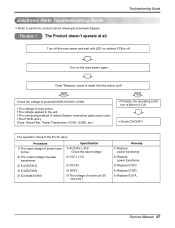
... stopped Indoor Fan is displayed in the Sleeping Mode, the wind speed is impossible to operate temperature regulating(L / M) and wind speed selecting. Caused by other parts except the remote controller When the mark ( ) is driven by the remote controller. Turn on main power. Troubleshooting Guide Trouble 2 Product doesn't operate with the...
... stopped Indoor Fan is displayed in the Sleeping Mode, the wind speed is impossible to operate temperature regulating(L / M) and wind speed selecting. Caused by other parts except the remote controller When the mark ( ) is driven by the remote controller. Turn on main power. Troubleshooting Guide Trouble 2 Product doesn't operate with the...

Service Manual
Page 71
... Vertical Louver • Confirm that there is DC +12V between pin (RED) of CN-UP/DOWN and GND. • Confirm that are catching and interfering parts in the rotation radial of MICOM - Troubleshooting Guide Trouble 5 When the louver does not operate. Between 60 , 61 , 62 and 63 of the Vertical Louver...
... Vertical Louver • Confirm that there is DC +12V between pin (RED) of CN-UP/DOWN and GND. • Confirm that are catching and interfering parts in the rotation radial of MICOM - Troubleshooting Guide Trouble 5 When the louver does not operate. Between 60 , 61 , 62 and 63 of the Vertical Louver...
Service Manual
Page 81
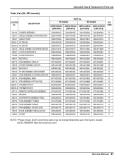
DESCRIPTION S4 chassis PART No. Exploded View & Replacement Parts List Parts List (S4, SE chassis) LOCATION No. SE chassis AMNH093D4A0 AMNC093D4A0 AMNH123DEA0 AMNC123DEA0 (LMN090HE) (LMN090CE) (LMN120HE) (LMN120CE) SVC CODE 131410 CHASSIS ASSEMBLY 3141A20019C 3141A20019C 3141A20034A 3141A20034A R 135311 GRILLE ASSEMBLY,FRONT(INDOOR)... 3301A20020A 3301A20020A R 135500 COVER 3550A30262A 3550A30262A 3550A30315A 3550A30315A R NOTE) *Please ensure GCSC since these parts may be changed depending upon the buyer's request. (GCSC WEBSITE http://biz.LGservice.com) Service Manual 81
DESCRIPTION S4 chassis PART No. Exploded View & Replacement Parts List Parts List (S4, SE chassis) LOCATION No. SE chassis AMNH093D4A0 AMNC093D4A0 AMNH123DEA0 AMNC123DEA0 (LMN090HE) (LMN090CE) (LMN120HE) (LMN120CE) SVC CODE 131410 CHASSIS ASSEMBLY 3141A20019C 3141A20019C 3141A20034A 3141A20034A R 135311 GRILLE ASSEMBLY,FRONT(INDOOR)... 3301A20020A 3301A20020A R 135500 COVER 3550A30262A 3550A30262A 3550A30315A 3550A30315A R NOTE) *Please ensure GCSC since these parts may be changed depending upon the buyer's request. (GCSC WEBSITE http://biz.LGservice.com) Service Manual 81

Service Manual
Page 83
.... Exploded View & Replacement Parts List Parts List (SP3 chassis) LOCATION No. AMNH093APM0 AMNC093APM0 AMNH123APM0 AMNC123APM0 (LMAN090HNS) (LMAN090CNS) (LMAN120HNS) (LMAN120CNS) SVC CODE 131410 CHASSIS ASSEMBLY 3141A20030C 3141A20030C 3141A20030C 3141A20030C R ... 5251AR1222R R 354210 EVAPORATOR ASSEMBLY,FIRST 5421A20072A 5421A20072A 5421A20072A 5421A20072A R 359012 FAN,TURBO 5900A00003A 5900A00003A 5900A00003A 5900A00003A R NOTE) *Please ensure GCSC since these parts may be changed depending upon the buyer's request. (GCSC WEBSITE http://biz.LGservice.com) Service Manual 83
.... Exploded View & Replacement Parts List Parts List (SP3 chassis) LOCATION No. AMNH093APM0 AMNC093APM0 AMNH123APM0 AMNC123APM0 (LMAN090HNS) (LMAN090CNS) (LMAN120HNS) (LMAN120CNS) SVC CODE 131410 CHASSIS ASSEMBLY 3141A20030C 3141A20030C 3141A20030C 3141A20030C R ... 5251AR1222R R 354210 EVAPORATOR ASSEMBLY,FIRST 5421A20072A 5421A20072A 5421A20072A 5421A20072A R 359012 FAN,TURBO 5900A00003A 5900A00003A 5900A00003A 5900A00003A R NOTE) *Please ensure GCSC since these parts may be changed depending upon the buyer's request. (GCSC WEBSITE http://biz.LGservice.com) Service Manual 83

Service Manual
Page 85
...6600L000013 6600L000013 R 263230-1 THERMISTOR,NTC 6323A20026A 6323A20026A R 263230-2 THERMISTOR,NTC 6323A20001N 6323A20001N R NOTE) *Please ensure GCSC since these parts may be changed depending upon the buyer's request. (GCSC WEBSITE http://biz.LGservice.com) Solenoid(Coil Assempy, Reverse) is only... for heat pump model. Service Manual 85 Description Part No. SVC A2UH243FA0(LMU240HE) A2UC243FA0 (LMU240CE) CODE 437210 PANEL ASSEMBLY,FRONT(SUB) 1A00197C 1A00197C R 137213-1 PANEL ASSEMBLY,SIDE ...
...6600L000013 6600L000013 R 263230-1 THERMISTOR,NTC 6323A20026A 6323A20026A R 263230-2 THERMISTOR,NTC 6323A20001N 6323A20001N R NOTE) *Please ensure GCSC since these parts may be changed depending upon the buyer's request. (GCSC WEBSITE http://biz.LGservice.com) Solenoid(Coil Assempy, Reverse) is only... for heat pump model. Service Manual 85 Description Part No. SVC A2UH243FA0(LMU240HE) A2UC243FA0 (LMU240CE) CODE 437210 PANEL ASSEMBLY,FRONT(SUB) 1A00197C 1A00197C R 137213-1 PANEL ASSEMBLY,SIDE ...


