
Service Manual
Page 1
website http://www.lgservice.com LG Multi Type Air Conditioner SERVICE MANUAL MODEL • Indoor Unit: Room Type AMNH093D4A0(LMN090HE) AMNH123DEA0 (LMN120HE) AMNC093D4A0(LMN090CE) AMNC123DEA0 (LMN120CE) Art Cool Type AMNH093APM0(LMAN090HNS) AMNH123APM0(LMAN120HNS) AMNC093APM0(LMAN090CNS) AMNC123APM0(LMAN120CNS) • Outdoor Unit: A2UH243FA0(LMU240HE) A2UC243FA0 (LMU240CE) LG CAUTION • BEFORE SERVICING THE UNIT, READ THE SAFETY PRECAUTIONS IN THIS MANUAL. • ONLY FOR AUTHORIZED SERVICE PERSONNEL.
website http://www.lgservice.com LG Multi Type Air Conditioner SERVICE MANUAL MODEL • Indoor Unit: Room Type AMNH093D4A0(LMN090HE) AMNH123DEA0 (LMN120HE) AMNC093D4A0(LMN090CE) AMNC123DEA0 (LMN120CE) Art Cool Type AMNH093APM0(LMAN090HNS) AMNH123APM0(LMAN120HNS) AMNC093APM0(LMAN090CNS) AMNC123APM0(LMAN120CNS) • Outdoor Unit: A2UH243FA0(LMU240HE) A2UC243FA0 (LMU240CE) LG CAUTION • BEFORE SERVICING THE UNIT, READ THE SAFETY PRECAUTIONS IN THIS MANUAL. • ONLY FOR AUTHORIZED SERVICE PERSONNEL.
Service Manual
Page 2
Multi type Air Conditioner Service Manual TABLE OF CONTENTS Model Number Nomenclature ...3 Symbols Used in this Manual ...4 Safety Precautions...5 Dimensions...11 Indoor Unit...11 Outdoor Unit ...12 Product Specifications ...13 Installation ...15 Installation Parts...15 Installation Tools...15 Select the best location ......
Multi type Air Conditioner Service Manual TABLE OF CONTENTS Model Number Nomenclature ...3 Symbols Used in this Manual ...4 Safety Precautions...5 Dimensions...11 Indoor Unit...11 Outdoor Unit ...12 Product Specifications ...13 Installation ...15 Installation Parts...15 Installation Tools...15 Select the best location ......
Service Manual
Page 3
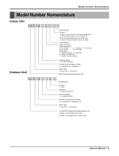
look type L : L- of Connectable Indoor Units Ex) A2U : Connectable max. 2 Indoor Units Service Manual 3 Model Number Nomenclature Model Number Nomenclature Indoor Unit AMN H 09 3 D 4 A 0 Serial Number Function A : Basic, L : Nano Plasma + Auto Clean(Wall Mounted) C: Plasma(Ceiling Cassette), G: Low Static ...
look type L : L- of Connectable Indoor Units Ex) A2U : Connectable max. 2 Indoor Units Service Manual 3 Model Number Nomenclature Model Number Nomenclature Indoor Unit AMN H 09 3 D 4 A 0 Serial Number Function A : Basic, L : Nano Plasma + Auto Clean(Wall Mounted) C: Plasma(Ceiling Cassette), G: Low Static ...

Service Manual
Page 5
...by the following instructions must be followed. WARNING This symbol indicates the possibility of control box securely. rated circuit breaker. Use this manual are as shown below. Use the correctly rated break- cuit and breaker. Safety Precautions Safety Precautions To prevent injury to follow ... electric shock. Install the panel and the cover Always install a dedicated cir- of death or serious injury. Service Manual 5 Be sure not to properties only. or an Authorized Service Center. • There is risk of fire or electric shock. • Do not disassemble or repair the...
...by the following instructions must be followed. WARNING This symbol indicates the possibility of control box securely. rated circuit breaker. Use this manual are as shown below. Use the correctly rated break- cuit and breaker. Safety Precautions Safety Precautions To prevent injury to follow ... electric shock. Install the panel and the cover Always install a dedicated cir- of death or serious injury. Service Manual 5 Be sure not to properties only. or an Authorized Service Center. • There is risk of fire or electric shock. • Do not disassemble or repair the...
Service Manual
Page 7
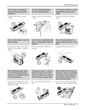
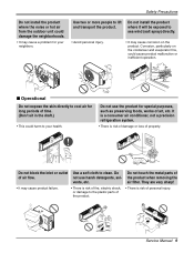
... store or use flammable Do not use the product in storm or hurricane. There is risk of property damage, failure of product, or electric shock. Service Manual 7 Stop operation and close the window in a gas or combustibles near the power cable. • There is risk of fire and electric shock. Do not...
... store or use flammable Do not use the product in storm or hurricane. There is risk of property damage, failure of product, or electric shock. Service Manual 7 Stop operation and close the window in a gas or combustibles near the power cable. • There is risk of fire and electric shock. Do not...
Service Manual
Page 9
... a soft cloth to lift and transport the product. They are very sharp! • It may cause a problem for long periods of art, etc. Wax Thinner Service Manual 9 Do not touch the metal parts of personal injury. Corrosion, particularly on the product. Safety Precautions Do not install the product where the noise or...
... a soft cloth to lift and transport the product. They are very sharp! • It may cause a problem for long periods of art, etc. Wax Thinner Service Manual 9 Do not touch the metal parts of personal injury. Corrosion, particularly on the product. Safety Precautions Do not install the product where the noise or...
Service Manual
Page 11
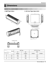
Dimensions Indoor Unit 1. Split Type Indoor H D W Dimensions 2. Art Cool Type Indoor Unit W D H Pipe Hole Hanger Hole Installation plate Fix Hole Dimension W H D Model mm mm mm Split Type S4 SE 9 kBtu/h 12 kBtu/h 840 895 270 282 153 165 ARTCOOL Type SP3 9 kBtu/h 12 kBtu/h 570 568 129 Service Manual 11
Dimensions Indoor Unit 1. Split Type Indoor H D W Dimensions 2. Art Cool Type Indoor Unit W D H Pipe Hole Hanger Hole Installation plate Fix Hole Dimension W H D Model mm mm mm Split Type S4 SE 9 kBtu/h 12 kBtu/h 840 895 270 282 153 165 ARTCOOL Type SP3 9 kBtu/h 12 kBtu/h 570 568 129 Service Manual 11
Service Manual
Page 13
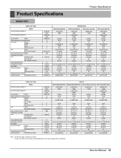
... the page "Combination Table" 2. Used / Diameter Noise Level (Sound Press,1m) H/M/L Temperature controller Coil Tube Size (OD) Fins per inch No. Service Manual 13 of Poles Input Running Current Fan Type No. Used / Diameter Noise Level (Sound Press,1m) H/M/L Temperature controller Coil Tube Size (OD) Fins per...(5.0) 18 2R,15C - 35.2*11.1*6.5(895*282*165) 9.5(20.9) 1/4 (6.35) 3/8 (9.52) 20 38.3*9.1*14.6(973*231*372) 353/719 (792) AMNH123DEA0 (LMN120HE) 3,023(3,516) 12,000 3,023(3,516) 12,000 9.4(332) 16~30 15 DL-88430LGIF DC36 0.15 Cross Flow Fan 1/3.74(95) 36 / 32 / 29...
... the page "Combination Table" 2. Used / Diameter Noise Level (Sound Press,1m) H/M/L Temperature controller Coil Tube Size (OD) Fins per inch No. Service Manual 13 of Poles Input Running Current Fan Type No. Used / Diameter Noise Level (Sound Press,1m) H/M/L Temperature controller Coil Tube Size (OD) Fins per...(5.0) 18 2R,15C - 35.2*11.1*6.5(895*282*165) 9.5(20.9) 1/4 (6.35) 3/8 (9.52) 20 38.3*9.1*14.6(973*231*372) 353/719 (792) AMNH123DEA0 (LMN120HE) 3,023(3,516) 12,000 3,023(3,516) 12,000 9.4(332) 16~30 15 DL-88430LGIF DC36 0.15 Cross Flow Fan 1/3.74(95) 36 / 32 / 29...
Service Manual
Page 15
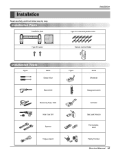
Installation Read carefully, and then follow step by step. Installation Parts Installation plate Type "B" screw Installation Type "A" screw and plastic anchor Remote Control Holder Installation Tools Figure Name Screw driver Electric Drill Measuring Tape, Knife Hole Core Drill Spanner Torque wrench Figure Name Ohmmeter Hexagonal wrench Ammeter Gas Leak Detector Thermometer, Level Flaring Tool Set Service Manual 15
Installation Read carefully, and then follow step by step. Installation Parts Installation plate Type "B" screw Installation Type "A" screw and plastic anchor Remote Control Holder Installation Tools Figure Name Screw driver Electric Drill Measuring Tape, Knife Hole Core Drill Spanner Torque wrench Figure Name Ohmmeter Hexagonal wrench Ammeter Gas Leak Detector Thermometer, Level Flaring Tool Set Service Manual 15
Service Manual
Page 17
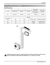
Installation Piping length and elevation Multi Piping Type Capacity(Btu/h) Max Elevation Max total length of Max length of each Min length of reliability. Service Manual 17 door unit (h1) Max elevation between each between indoor units (h2) 24k 30m(100ft) 15m(50ft) 3m(10ft) 7.5m(25ft) 7.5m(25ft) Indoor Capacity (...
Installation Piping length and elevation Multi Piping Type Capacity(Btu/h) Max Elevation Max total length of Max length of each Min length of reliability. Service Manual 17 door unit (h1) Max elevation between each between indoor units (h2) 24k 30m(100ft) 15m(50ft) 3m(10ft) 7.5m(25ft) 7.5m(25ft) Indoor Capacity (...
Service Manual
Page 19
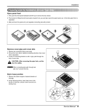
... came out, In this panel a bit, and separate connecting wire with product. Pipe hole Adhesive Only one desiring direction Connecting part Drain hose rubber cap Service Manual 19 First, push the front panel backward and lift it up the cover side of desired connecting direction, then cover side is left or right...
... came out, In this panel a bit, and separate connecting wire with product. Pipe hole Adhesive Only one desiring direction Connecting part Drain hose rubber cap Service Manual 19 First, push the front panel backward and lift it up the cover side of desired connecting direction, then cover side is left or right...
Service Manual
Page 21
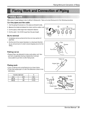
... pipe/tube. 2. Outside diameter mm inch Ø6.35 1/4 Ø9.52 3/8 A mm 0~0.5 0~0.5 Copper tube Handle "A" Bar Bar Yoke Cone Copper pipe Clamp handle Red arrow mark Service Manual 21 Measure the distance between the indoor and the outdoor unit. Cut the cable 1.5m (5.0ft) longer than measured distance. Flaring Work and Connection of...
... pipe/tube. 2. Outside diameter mm inch Ø6.35 1/4 Ø9.52 3/8 A mm 0~0.5 0~0.5 Copper tube Handle "A" Bar Bar Yoke Cone Copper pipe Clamp handle Red arrow mark Service Manual 21 Measure the distance between the indoor and the outdoor unit. Cut the cable 1.5m (5.0ft) longer than measured distance. Flaring Work and Connection of...
Service Manual
Page 23
Press the lower left and right. Tighten the flare nut with vinyl tape Drain hose Vinyl tape(wide) Service Manual 23 When extending the drain hose at the indoor unit, install the drain pipe. Outside diameter mm inch Ø6.35 1/4 Ø9.52 3/8 Torque kg.m 1.8 4.2 3. Overlap ...
Press the lower left and right. Tighten the flare nut with vinyl tape Drain hose Vinyl tape(wide) Service Manual 23 When extending the drain hose at the indoor unit, install the drain pipe. Outside diameter mm inch Ø6.35 1/4 Ø9.52 3/8 Torque kg.m 1.8 4.2 3. Overlap ...
Service Manual
Page 25
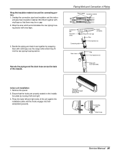
... may be no gap. 2. Wrap the insulation material around the connecting portion. 1. Remove the spacer. 2. Piping for passage through piping hole Connecting cable Drain hose Service Manual 25
... may be no gap. 2. Wrap the insulation material around the connecting portion. 1. Remove the spacer. 2. Piping for passage through piping hole Connecting cable Drain hose Service Manual 25
Service Manual
Page 27
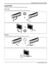
Follow the instruction below. Bad case • Following bending type from right to left piping. Flaring Work and Connection of clamp and unfold the tubing to the tubing. Good case • Press on the upper side of Piping Installation Information. For left may cause damage to downward slowly. Service Manual 27
Follow the instruction below. Bad case • Following bending type from right to left piping. Flaring Work and Connection of clamp and unfold the tubing to the tubing. Good case • Press on the upper side of Piping Installation Information. For left may cause damage to downward slowly. Service Manual 27

Service Manual
Page 29
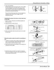
Outdoor Align the center of Piping Finally, tighten the flare nut with torque wrench until the wrench clicks. • When tightening the flare nut with torque wrench, ensure the direction for tightening follows the arrow on the wrench. Outside diameter mm inch Ø6.35 1/4 Ø9.52 3/8 Torque kg.m 1.8 4.2 Outdoor unit A-UNIT Gas side piping B-UNIT Liquid side piping Torque wrench Service Manual 29 Flaring Work and Connection of the pipings and sufficiently tighten the flare nut by hand.
Outdoor Align the center of Piping Finally, tighten the flare nut with torque wrench until the wrench clicks. • When tightening the flare nut with torque wrench, ensure the direction for tightening follows the arrow on the wrench. Outside diameter mm inch Ø6.35 1/4 Ø9.52 3/8 Torque kg.m 1.8 4.2 Outdoor unit A-UNIT Gas side piping B-UNIT Liquid side piping Torque wrench Service Manual 29 Flaring Work and Connection of the pipings and sufficiently tighten the flare nut by hand.
Service Manual
Page 31
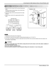
... wiring capable of wire and wiring method, etc). • Every wire must be connected firmly. • No wire should be allowed to the Outdoor unit. 1. Service Manual 31 Secure the cable onto the control board with local codes while running the wire from the unit by loosening the screw. Refix the cover...
... wiring capable of wire and wiring method, etc). • Every wire must be connected firmly. • No wire should be allowed to the Outdoor unit. 1. Service Manual 31 Secure the cable onto the control board with local codes while running the wire from the unit by loosening the screw. Refix the cover...
Service Manual
Page 33
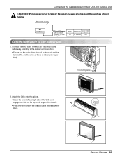
... to the terminals on the top inside edge of the chassis. • Press the Grille toward the chassis until it will be back into place. Service Manual 33 Connecting the Cable between Indoor Unit and Outdoor Unit CAUTION: Provide a circuit breaker between power source and the unit as those of indoor unit...
... to the terminals on the top inside edge of the chassis. • Press the Grille toward the chassis until it will be back into place. Service Manual 33 Connecting the Cable between Indoor Unit and Outdoor Unit CAUTION: Provide a circuit breaker between power source and the unit as those of indoor unit...
Service Manual
Page 35
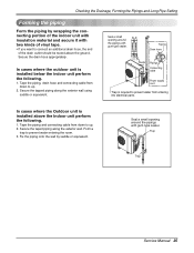
... the piping and connecting cable from entering into electrical parts. Secure the drain hose appropriately. Secure the tapped piping along the exterior wall. Trap Trap Service Manual 35
... the piping and connecting cable from entering into electrical parts. Secure the drain hose appropriately. Secure the tapped piping along the exterior wall. Trap Trap Service Manual 35
Service Manual
Page 37
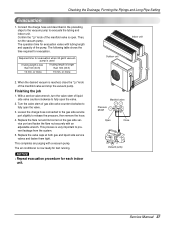
... Then, run the vacuum pump. This process is reached, close the "Lo" knob of the pump. or more 15 min. With a service valve wrench, turn the valve stem of gas side valve counter-clockwise to evacuate the tubing and indoor unit. Required time for test running. ...a vacuum pump. The following table shows the time required for each indoor unit. Manifold valve Pressure gauge Lo Hi Open Close Vacuum pump Service Manual 37 or more Indoor unit Outdoor unit 2. Checking the Drainage, Forming the Pipings and Long Pipe Setting Evacuation 1. Connect the charge hose ...
... Then, run the vacuum pump. This process is reached, close the "Lo" knob of the pump. or more 15 min. With a service valve wrench, turn the valve stem of gas side valve counter-clockwise to evacuate the tubing and indoor unit. Required time for test running. ...a vacuum pump. The following table shows the time required for each indoor unit. Manifold valve Pressure gauge Lo Hi Open Close Vacuum pump Service Manual 37 or more Indoor unit Outdoor unit 2. Checking the Drainage, Forming the Pipings and Long Pipe Setting Evacuation 1. Connect the charge hose ...


