

Owners Manual
Page 2
...responsible party for proper grounding and, in particular, specifies that to provide reasonable protection against harmful interference when the product is : LG Electronics U.S.A., Inc.,1000 Sylvan Avenue, Englewood Cliffs, NJ. That is, a single outlet circuit which powers only that appliance ...apparatus should record requested information here and retain this equipment if an unauthorized change or modification is provided to call the cable TV system installer's attention to the presence of the National Electric Code (U.S.A.). Do not overload wall outlets. Periodically examine...
...responsible party for proper grounding and, in particular, specifies that to provide reasonable protection against harmful interference when the product is : LG Electronics U.S.A., Inc.,1000 Sylvan Avenue, Englewood Cliffs, NJ. That is, a single outlet circuit which powers only that appliance ...apparatus should record requested information here and retain this equipment if an unauthorized change or modification is provided to call the cable TV system installer's attention to the presence of the National Electric Code (U.S.A.). Do not overload wall outlets. Periodically examine...

Owners Manual
Page 4
... Remote Control Battery Installation 11 Front Panel 12 Function Display Window 13 Remote Control Overview 14 Rear Panel 15 HOOKUP Connections 16-21 Connecting Antenna/Cable TV to Recorder Combi Receiver 16 Connecting to a TV 17 Accessory Audio/Video (A/V) Connections to Recorder Combi Receiver 18 Connecting a Digital Camcorder 19 Radio Antenna...
... Remote Control Battery Installation 11 Front Panel 12 Function Display Window 13 Remote Control Overview 14 Rear Panel 15 HOOKUP Connections 16-21 Connecting Antenna/Cable TV to Recorder Combi Receiver 16 Connecting to a TV 17 Accessory Audio/Video (A/V) Connections to Recorder Combi Receiver 18 Connecting a Digital Camcorder 19 Radio Antenna...

Owners Manual
Page 16
... you are various ways you can receive all midband, super band, and hyperband channels. (All cable channels.) Cable Service With Cable Box If a converter is required in jack (record deck) of Typical Cable Box Cable TV Wall Jack ip If your antenna lead wire is connected to your TV without a converter or... it is not necessary to do Auto Channel Set as indicated on to connect, there are using TRK/ PRESET(-/+) (v / V) or number (0-9) of cable from your antenna. With this connection, you could be distorted by the copy protection system. Use only one of your TV, VCR, Stereo System or...
... you are various ways you can receive all midband, super band, and hyperband channels. (All cable channels.) Cable Service With Cable Box If a converter is required in jack (record deck) of Typical Cable Box Cable TV Wall Jack ip If your antenna lead wire is connected to your TV without a converter or... it is not necessary to do Auto Channel Set as indicated on to connect, there are using TRK/ PRESET(-/+) (v / V) or number (0-9) of cable from your antenna. With this connection, you could be distorted by the copy protection system. Use only one of your TV, VCR, Stereo System or...

Owners Manual
Page 17
...® pro) connection If your television is turned off, press and hold TRK/PRESET(-/+) (v or V) on the TV using the 75-ohm Coaxial Cable supplied (R). How to set the Recorder Combi Receiver's RF output channel When the Recorder Combi Receiver is a high-definition or "digital ready" television, you...S-Video connection 1 Connect the S-VIDEO OUT jack on the Recorder Combi Receiver to the S-Video in jack on the TV using the audio cables (A). ote If you may take advantage of Recorder Combi Receiver Audio/Video connection 1 Connect the VIDEO OUT jack on the Recorder Combi Receiver to...
...® pro) connection If your television is turned off, press and hold TRK/PRESET(-/+) (v or V) on the TV using the 75-ohm Coaxial Cable supplied (R). How to set the Recorder Combi Receiver's RF output channel When the Recorder Combi Receiver is a high-definition or "digital ready" television, you...S-Video connection 1 Connect the S-VIDEO OUT jack on the Recorder Combi Receiver to the S-Video in jack on the TV using the audio cables (A). ote If you may take advantage of Recorder Combi Receiver Audio/Video connection 1 Connect the VIDEO OUT jack on the Recorder Combi Receiver to...

Owners Manual
Page 18
DVD) are equipped with OPTICAL OUT jack, connect them to the AUDIO/VIDEO OUT jacks on the front panel is not available. 18 ote If you use the S-VIDEO IN jack on the front panel, the VIDEO jack on your accessory component, using the optional audio/video cables. If the auxiliary devices (e.g. Connections (Continued) Accessory Audio/Video (A/V) Connections to Recorder Combi Receiver Connect the VCR IN LINE 1 or VIDEO/AUDIO(L/R) jacks on the Recorder Combi Receiver to the OPTICAL IN jack of the Recorder Combi Receiver.
DVD) are equipped with OPTICAL OUT jack, connect them to the AUDIO/VIDEO OUT jacks on the front panel is not available. 18 ote If you use the S-VIDEO IN jack on the front panel, the VIDEO jack on your accessory component, using the optional audio/video cables. If the auxiliary devices (e.g. Connections (Continued) Accessory Audio/Video (A/V) Connections to Recorder Combi Receiver Connect the VCR IN LINE 1 or VIDEO/AUDIO(L/R) jacks on the Recorder Combi Receiver to the OPTICAL IN jack of the Recorder Combi Receiver.

Owners Manual
Page 19
... Receiver. DV Digital Camcorder DV IN/OUT Radio Antenna Connections Connect the supplied FM/AM antennas for connection to the FM antenna connector. Use a DV cable (not supplied) to connect the DV in/out jack of your DV Digital Camcorder to horizontal as close to the front panel DV IN jack...
... Receiver. DV Digital Camcorder DV IN/OUT Radio Antenna Connections Connect the supplied FM/AM antennas for connection to the FM antenna connector. Use a DV cable (not supplied) to connect the DV in/out jack of your DV Digital Camcorder to horizontal as close to the front panel DV IN jack...
Owners Manual
Page 20
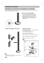
...You cannot detach the speaker from speaker stands as possible. After connecting the speaker cables to the appropriate terminals on the System cable. 3 Close the ferrite core unit it clicks. Connect the speaker cables and assemble the front speakers from the stand after assembling the front and rear ...is short as much as illustrated. Connections (Continued) Assembling and Connecting to this unit). How to connect the Speakers Connect the speaker cables to the appropriate terminals on the bottom of each front speaker and attach the front speakers to the fig.3 and comment.). How ...
...You cannot detach the speaker from speaker stands as possible. After connecting the speaker cables to the appropriate terminals on the System cable. 3 Close the ferrite core unit it clicks. Connect the speaker cables and assemble the front speakers from the stand after assembling the front and rear ...is short as much as illustrated. Connections (Continued) Assembling and Connecting to this unit). How to connect the Speakers Connect the speaker cables to the appropriate terminals on the bottom of each front speaker and attach the front speakers to the fig.3 and comment.). How ...
Owners Manual
Page 21
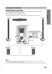
...to avoid excessive output on the Recorder Combi Receiver to the SYSTEM SELECTOR rear of the Active Subwoofer Speaker, using the supplied speaker cables. HOOKUP Connections (Continued) Speaker System Connections Connect the SYSTEM on the speakers. 21 to + and - If the... cables are reversed, the sound will be distorted and will lack base. System cable otes Be sure to match the speaker cable to the appropriate terminal on the components: + to -. Connect the speakers using the supplied System...
...to avoid excessive output on the Recorder Combi Receiver to the SYSTEM SELECTOR rear of the Active Subwoofer Speaker, using the supplied speaker cables. HOOKUP Connections (Continued) Speaker System Connections Connect the SYSTEM on the speakers. 21 to + and - If the... cables are reversed, the sound will be distorted and will lack base. System cable otes Be sure to match the speaker cable to the appropriate terminal on the components: + to -. Connect the speakers using the supplied System...

Owners Manual
Page 26
... require additional steps. 7 Press SETUP to Recorder Combi Receiver" on page 16 1 Press SETUP. The tuner will take you are using basic cable to begin the channel search. Preparation: Connect the Recorder Combi Receiver to the desired type of three levels to set appropriately (TV or CATV)... Press SETUP. Add/Del Clock Set TV Aspect Progressive Scan Power Save Mode Factory Setting Stop 11% Prev. Most menus consist of antenna or cable TV system, as shown previous (Tuning Band Select) to initial screen. These include VHF channels 2-13, UHF channels 14-69 and CATV channels ...
... require additional steps. 7 Press SETUP to Recorder Combi Receiver" on page 16 1 Press SETUP. The tuner will take you are using basic cable to begin the channel search. Preparation: Connect the Recorder Combi Receiver to the desired type of three levels to set appropriately (TV or CATV)... Press SETUP. Add/Del Clock Set TV Aspect Progressive Scan Power Save Mode Factory Setting Stop 11% Prev. Most menus consist of antenna or cable TV system, as shown previous (Tuning Band Select) to initial screen. These include VHF channels 2-13, UHF channels 14-69 and CATV channels ...

Owners Manual
Page 35
Some DVDs require specific operation or allow only limited operation during playback. Cable channels are broadcast with both a main and a Secondary Audio Program (SAP). Changing TV Audio Channel Some TV programs are numbered 1 through 69. Indicates the Recording ...
Some DVDs require specific operation or allow only limited operation during playback. Cable channels are broadcast with both a main and a Secondary Audio Program (SAP). Changing TV Audio Channel Some TV programs are numbered 1 through 69. Indicates the Recording ...
Owners Manual
Page 52
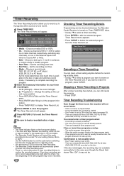
... program. • Start Time - OK Edit CLEAR Delete TIMER REC Timer Rec Close Canceling a Timer Recording You can be recorded. Choose a record mode. na or cable channels respectively, excluding skip channels), or one of one right after filling in Progress After a timer recording has started, you can still cancel the program...
... program. • Start Time - OK Edit CLEAR Delete TIMER REC Timer Rec Close Canceling a Timer Recording You can be recorded. Choose a record mode. na or cable channels respectively, excluding skip channels), or one of one right after filling in Progress After a timer recording has started, you can still cancel the program...
Owners Manual
Page 53
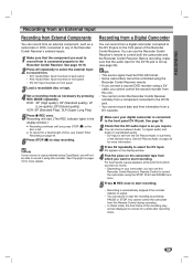
... pressing PAUSE or STOP. ips • The source signal must be DVC-SD format. • Some camcorders cannot be able to record it using a DV cable, you cannot control the second recorder from this Recorder Combi Receiver. DVD: XP (High quality), SP (Standard quality), LP (Low quality), EP (Extend quality). See...
... pressing PAUSE or STOP. ips • The source signal must be DVC-SD format. • Some camcorders cannot be able to record it using a DV cable, you cannot control the second recorder from this Recorder Combi Receiver. DVD: XP (High quality), SP (Standard quality), LP (Low quality), EP (Extend quality). See...

Owners Manual
Page 54
... properly, or the camcorder is updating information for input and output of tape, or if the power fails in the source component, or the DV cable becomes disconnected. • If DV Record Audio is present, DV Record Audio will be reset to Audio 1 automatically. Too many devices connected. There... (not 44.1kHz). • Picture disturbance on your Camcorder to camera mode, turn down the volume of your TV screen when using a single DV cable for DV. The Recorder Combi Receiver can be a howling sound. 54 otes • Depending on the connected camcorder, you set to Audio 2, but ...
... properly, or the camcorder is updating information for input and output of tape, or if the power fails in the source component, or the DV cable becomes disconnected. • If DV Record Audio is present, DV Record Audio will be reset to Audio 1 automatically. Too many devices connected. There... (not 44.1kHz). • Picture disturbance on your Camcorder to camera mode, turn down the volume of your TV screen when using a single DV cable for DV. The Recorder Combi Receiver can be a howling sound. 54 otes • Depending on the connected camcorder, you set to Audio 2, but ...

Owners Manual
Page 71
...Recorder Combi Receiver signal output. Discs recorded with the playback side down . Turn on the disc tray correctly inside the guide. Connect the audio cable securely. Insert a disc or tape. (Check that the disc indicator on another DVD player. see page 33. No solution. 71 Recorder ... Picture from Memory" on the TV so the picture from the Recorder Combi Receiver. The Movie Rating level is off . Antenna or cables are not connected securely. Turn on another VCR. Connect the component directly to play disc recorded on this Recorder Combi Receiver on the ...
...Recorder Combi Receiver signal output. Discs recorded with the playback side down . Turn on the disc tray correctly inside the guide. Connect the audio cable securely. Insert a disc or tape. (Check that the disc indicator on another DVD player. see page 33. No solution. 71 Recorder ... Picture from Memory" on the TV so the picture from the Recorder Combi Receiver. The Movie Rating level is off . Antenna or cables are not connected securely. Turn on another VCR. Connect the component directly to play disc recorded on this Recorder Combi Receiver on the ...
Owners Manual
Page 74
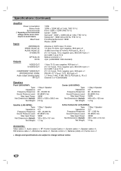
... Sound Pressure Level: 83 dB/W (1m) Max Input Power: 300W Net Dimensions (WxHxD): 295 x 432 x 414 mm Net Weight: 14 kg Accessories: Video cable x 1, Audio cable x 1, RF 75-ohm Coaxial Cable x 1, System cable x 1, Speaker cable x 5, FM Antenna cable x 1, AM Antenna cable x 1, Remote control x 1, Batteries (AAA) x 2, Ferrite core x 1 Design and specifications are subject to change without notice. 74
... Sound Pressure Level: 83 dB/W (1m) Max Input Power: 300W Net Dimensions (WxHxD): 295 x 432 x 414 mm Net Weight: 14 kg Accessories: Video cable x 1, Audio cable x 1, RF 75-ohm Coaxial Cable x 1, System cable x 1, Speaker cable x 5, FM Antenna cable x 1, AM Antenna cable x 1, Remote control x 1, Batteries (AAA) x 2, Ferrite core x 1 Design and specifications are subject to change without notice. 74


