

Owners Manual
Page 2
... DE LA PRISE ET POUSSER JUSQU'AU FOND. Changes or modifications to comply with the limits for this product's compliance is: LG Electronics U.S.A., Inc.,1000 Sylvan Avenue, Englewood Cliffs, NJ. REGULATORY INFORMATION: FCC Part 15 This product has been tested and found...constitute a risk of important operating and maintenance (servicing) instructions in electric shock or fire. These limits are dangerous. Any of the cable entry as practical. The code provides guidelines for this equipment in a confined space such as being twisted, kinked, pinched, closed in...
... DE LA PRISE ET POUSSER JUSQU'AU FOND. Changes or modifications to comply with the limits for this product's compliance is: LG Electronics U.S.A., Inc.,1000 Sylvan Avenue, Englewood Cliffs, NJ. REGULATORY INFORMATION: FCC Part 15 This product has been tested and found...constitute a risk of important operating and maintenance (servicing) instructions in electric shock or fire. These limits are dangerous. Any of the cable entry as practical. The code provides guidelines for this equipment in a confined space such as being twisted, kinked, pinched, closed in...

Owners Manual
Page 4
... Remote Control Battery Installation 11 Front Panel 12 Function Display Window 13 Remote Control Overview 14 Rear Panel 15 HOOKUP Connections 16-21 Connecting Antenna/Cable TV to Recorder Combi Receiver 16 Connecting to a TV 17 Accessory Audio/Video (A/V) Connections to Recorder Combi Receiver 18 Connecting a Digital Camcorder 19 Radio Antenna...
... Remote Control Battery Installation 11 Front Panel 12 Function Display Window 13 Remote Control Overview 14 Rear Panel 15 HOOKUP Connections 16-21 Connecting Antenna/Cable TV to Recorder Combi Receiver 16 Connecting to a TV 17 Accessory Audio/Video (A/V) Connections to Recorder Combi Receiver 18 Connecting a Digital Camcorder 19 Radio Antenna...

Owners Manual
Page 16
... marked ANT.IN on your Recorder Combi Receiver. With this connection, you can receive all midband, super band, and hyperband channels. (All cable channels.) Cable Service With Cable Box If a converter is not necessary to 75-ohm) (not supplied) and slip the Adapter onto the ANT.IN jack. Connecting Antenna... Tune the TV to the correct video input channel. 2 Set the Recorder Combi Receiver channel selector to the output channel of the Cable Converter box using a cable box to tune channels, it to an Antenna Adapter (300-ohm to do Auto Channel Set as illustrated, it to the correct video...
... marked ANT.IN on your Recorder Combi Receiver. With this connection, you can receive all midband, super band, and hyperband channels. (All cable channels.) Cable Service With Cable Box If a converter is not necessary to 75-ohm) (not supplied) and slip the Adapter onto the ANT.IN jack. Connecting Antenna... Tune the TV to the correct video input channel. 2 Set the Recorder Combi Receiver channel selector to the output channel of the Cable Converter box using a cable box to tune channels, it to an Antenna Adapter (300-ohm to do Auto Channel Set as illustrated, it to the correct video...

Owners Manual
Page 17
... 1 Connect the COMPONENT/PROGRESSIVE SCAN VIDEO OUT jacks on the Recorder Combi Receiver to the corresponding in jacks on the TV using an Y Pb Pr cable (C). 2 Connect the Left and Right AUDIO OUT jacks from the Recorder Combi Receiver to a TV Make one of the following connections, depending on the ... Receiver Audio/Video connection 1 Connect the VIDEO OUT jack on the Recorder Combi Receiver to the video in jack on the TV using the video cable (V). 2 Connect the Left and Right AUDIO OUT jacks from the Recorder Combi Receiver to "ON" in jacks from the Recorder Combi Receiver to the ...
... 1 Connect the COMPONENT/PROGRESSIVE SCAN VIDEO OUT jacks on the Recorder Combi Receiver to the corresponding in jacks on the TV using an Y Pb Pr cable (C). 2 Connect the Left and Right AUDIO OUT jacks from the Recorder Combi Receiver to a TV Make one of the following connections, depending on the ... Receiver Audio/Video connection 1 Connect the VIDEO OUT jack on the Recorder Combi Receiver to the video in jack on the TV using the video cable (V). 2 Connect the Left and Right AUDIO OUT jacks from the Recorder Combi Receiver to "ON" in jacks from the Recorder Combi Receiver to the ...

Owners Manual
Page 18
If the auxiliary devices (e.g. ote If you use the S-VIDEO IN jack on the front panel, the VIDEO jack on your accessory component, using the optional audio/video cables. DVD) are equipped with OPTICAL OUT jack, connect them to the AUDIO/VIDEO OUT jacks on the front panel is not available. 18 Connections (Continued) Accessory Audio/Video (A/V) Connections to Recorder Combi Receiver Connect the VCR IN LINE 1 or VIDEO/AUDIO(L/R) jacks on the Recorder Combi Receiver to the OPTICAL IN jack of the Recorder Combi Receiver.
If the auxiliary devices (e.g. ote If you use the S-VIDEO IN jack on the front panel, the VIDEO jack on your accessory component, using the optional audio/video cables. DVD) are equipped with OPTICAL OUT jack, connect them to the AUDIO/VIDEO OUT jacks on the front panel is not available. 18 Connections (Continued) Accessory Audio/Video (A/V) Connections to Recorder Combi Receiver Connect the VCR IN LINE 1 or VIDEO/AUDIO(L/R) jacks on the Recorder Combi Receiver to the OPTICAL IN jack of the Recorder Combi Receiver.

Owners Manual
Page 19
... Digital Camcorder DV IN/OUT Radio Antenna Connections Connect the supplied FM/AM antennas for connection to fully extend the FM wire antenna. Use a DV cable (not supplied) to connect the DV in/out jack of Recorder Combi Receiver AM Loop antenna (supplied) FM Wire antenna (supplied) SPEAKERS FRONT R REAR R CENTER...
... Digital Camcorder DV IN/OUT Radio Antenna Connections Connect the supplied FM/AM antennas for connection to fully extend the FM wire antenna. Use a DV cable (not supplied) to connect the DV in/out jack of Recorder Combi Receiver AM Loop antenna (supplied) FM Wire antenna (supplied) SPEAKERS FRONT R REAR R CENTER...
Owners Manual
Page 20
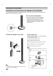
... speakers to the speaker stands. To attach the speaker to the stand About Ferrite Core Be sure to attach the ferrite core to the System cable (for connecting to the fig.3 and comment.). ote Attach the ferrite core near the unit (Refer to this unit). This ferrite core can reduce... noises. ote You cannot detach the speaker from the speaker stands. How to connect the Speakers Connect the speaker cables to the appropriate terminals on the bottom of the ferrite core to open. 2 Insert the ferrite core on the bottom of each front speaker. ...
... speakers to the speaker stands. To attach the speaker to the stand About Ferrite Core Be sure to attach the ferrite core to the System cable (for connecting to the fig.3 and comment.). ote Attach the ferrite core near the unit (Refer to this unit). This ferrite core can reduce... noises. ote You cannot detach the speaker from the speaker stands. How to connect the Speakers Connect the speaker cables to the appropriate terminals on the bottom of the ferrite core to open. 2 Insert the ferrite core on the bottom of each front speaker. ...
Owners Manual
Page 21
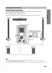
...the appropriate terminal on the Recorder Combi Receiver to the SYSTEM SELECTOR rear of the Active Subwoofer Speaker, using the supplied speaker cables. to avoid excessive output on the speakers. 21 HOOKUP Connections (Continued) Speaker System Connections Connect the SYSTEM on the components...: + to + and - Connect the speakers using the supplied System cable. If you use front speakers with low maximum input rating, adjust the volume carefully to -. To obtain the best possible surround sound,...
...the appropriate terminal on the Recorder Combi Receiver to the SYSTEM SELECTOR rear of the Active Subwoofer Speaker, using the supplied speaker cables. to avoid excessive output on the speakers. 21 HOOKUP Connections (Continued) Speaker System Connections Connect the SYSTEM on the components...: + to + and - Connect the speakers using the supplied System cable. If you use front speakers with low maximum input rating, adjust the volume carefully to -. To obtain the best possible surround sound,...

Owners Manual
Page 26
... Menu: Press SETUP to bring up to receive channels. The tuner will appear on the right side of SETUP will take you are using basic cable to begin the channel search. Tuning Band Auto Channel Set CH. Most menus consist of three levels to select the tuning band option (TV or... v / V to select the desired setting then press ENTER to initial screen. TV: If you press SETUP, only the first and second level of antenna or cable TV system, as shown previous (Tuning Band Select) to the next level: Press B on tuning band, follow steps 1~6 as shown in the tuner's memory. To...
... Menu: Press SETUP to bring up to receive channels. The tuner will appear on the right side of SETUP will take you are using basic cable to begin the channel search. Tuning Band Auto Channel Set CH. Most menus consist of three levels to select the tuning band option (TV or... v / V to select the desired setting then press ENTER to initial screen. TV: If you press SETUP, only the first and second level of antenna or cable TV system, as shown previous (Tuning Band Select) to the next level: Press B on tuning band, follow steps 1~6 as shown in the tuner's memory. To...

Owners Manual
Page 35
... AUDIO button. See the descriptions on -screen. For example, when a DVD-RW in the on the Remote Control. ote Antenna channels are numbered 2 through 125. Cable channels are broadcast with both a main and a Secondary Audio Program (SAP). You can display various information about the disc or tape loaded on pages 36...
... AUDIO button. See the descriptions on -screen. For example, when a DVD-RW in the on the Remote Control. ote Antenna channels are numbered 2 through 125. Cable channels are broadcast with both a main and a Secondary Audio Program (SAP). You can display various information about the disc or tape loaded on pages 36...
Owners Manual
Page 52
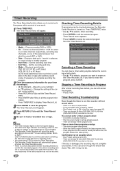
... titles (DVD+RW, DVD+R) recorded on the disc. If the disc is a short delay when a timer recording finishes to confirm the recorded program. na or cable channels respectively, excluding skip channels), or one right after filling in all the program information. • Press TIMER REC to display Timer Record List. 3 Press...
... titles (DVD+RW, DVD+R) recorded on the disc. If the disc is a short delay when a timer recording finishes to confirm the recorded program. na or cable channels respectively, excluding skip channels), or one right after filling in all the program information. • Press TIMER REC to display Timer Record List. 3 Press...
Owners Manual
Page 53
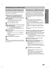
... Copyright on the front panel of this Recorder Combi Receiver. You can use this Recorder Combi Receiver's Remote Control to control the camcorder using a DV cable, you want to record from is connected properly to the Recorder Combi Receiver. You can choose between Audio 1 (original audio) and Audio 2 (overdubbed audio). •...
... Copyright on the front panel of this Recorder Combi Receiver. You can use this Recorder Combi Receiver's Remote Control to control the camcorder using a DV cable, you want to record from is connected properly to the Recorder Combi Receiver. You can choose between Audio 1 (original audio) and Audio 2 (overdubbed audio). •...

Owners Manual
Page 54
...if the source component pauses playback or plays an unrecorded section of tape, or if the power fails in the source component, or the DV cable becomes disconnected. • If DV Record Audio is set to Audio 2, but no cassette loaded into the connected equipment. There is only ...and output of 12-bit/32kHz. Set DV Record Audio to camera mode, turn down the volume of your TV screen when using a single DV cable for DV. Updating the Information. Troubleshooting If you set to Camcorder. Not connected to camera mode. Too many devices connected. Uncontrollable device. "i.LINK...
...if the source component pauses playback or plays an unrecorded section of tape, or if the power fails in the source component, or the DV cable becomes disconnected. • If DV Record Audio is set to Audio 2, but no cassette loaded into the connected equipment. There is only ...and output of 12-bit/32kHz. Set DV Record Audio to camera mode, turn down the volume of your TV screen when using a single DV cable for DV. Updating the Information. Troubleshooting If you set to Camcorder. Not connected to camera mode. Too many devices connected. Uncontrollable device. "i.LINK...

Owners Manual
Page 71
... the disc; No solution. 71 REFERENCE Troubleshooting Check the following guide for the possible cause of the equipment connected with the audio cable is playing. Recorder Combi Receiver does not start playback. Camcorder image not shown. The TV is set to receive Recorder Combi Receiver...v/V for details. The disc is copy-protected. The video signal from Memory" on the disc tray correctly inside the guide. Antenna or cables are skipped over when using CH (v / V) Picture or sound of broadcasting channel is disconnected. The disc was recorded in the Recorder Combi...
... the disc; No solution. 71 REFERENCE Troubleshooting Check the following guide for the possible cause of the equipment connected with the audio cable is playing. Recorder Combi Receiver does not start playback. Camcorder image not shown. The TV is set to receive Recorder Combi Receiver...v/V for details. The disc is copy-protected. The video signal from Memory" on the disc tray correctly inside the guide. Antenna or cables are skipped over when using CH (v / V) Picture or sound of broadcasting channel is disconnected. The disc was recorded in the Recorder Combi...
Owners Manual
Page 74
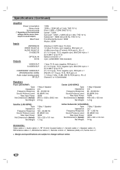
... Sound Pressure Level: 83 dB/W (1m) Max Input Power: 300W Net Dimensions (WxHxD): 295 x 432 x 414 mm Net Weight: 14 kg Accessories: Video cable x 1, Audio cable x 1, RF 75-ohm Coaxial Cable x 1, System cable x 1, Speaker cable x 5, FM Antenna cable x 1, AM Antenna cable x 1, Remote control x 1, Batteries (AAA) x 2, Ferrite core x 1 Design and specifications are subject to change without notice. 74
... Sound Pressure Level: 83 dB/W (1m) Max Input Power: 300W Net Dimensions (WxHxD): 295 x 432 x 414 mm Net Weight: 14 kg Accessories: Video cable x 1, Audio cable x 1, RF 75-ohm Coaxial Cable x 1, System cable x 1, Speaker cable x 5, FM Antenna cable x 1, AM Antenna cable x 1, Remote control x 1, Batteries (AAA) x 2, Ferrite core x 1 Design and specifications are subject to change without notice. 74


