
Owner's Manual
Page 2
... extension cords are frayed power cords and broken plugs. Call your service technician for its installation, use, and servicing. Use only a stand recommended by the supplier. Do not throw any way, please contact the manufacturer or the nearest authorized repair service provider for this display. Some internal parts carry hazardous voltages. When the display is used as the main disconnection device. On Safety Use only the power cord supplied with...
... extension cords are frayed power cords and broken plugs. Call your service technician for its installation, use, and servicing. Use only a stand recommended by the supplier. Do not throw any way, please contact the manufacturer or the nearest authorized repair service provider for this display. Some internal parts carry hazardous voltages. When the display is used as the main disconnection device. On Safety Use only the power cord supplied with...

Owner's Manual
Page 3
..., etc. On Disposal The fluorescent lamp used under any mode except the recommended resolution, some afterimages. Do not press the LCD screen with ventilation openings in a fire hazard. They make an ideal container in accordance to obtain the best image quality for your finger for a long time as Red, Green or Blue spots on the screen. On Repacking Do not throw away the...
..., etc. On Disposal The fluorescent lamp used under any mode except the recommended resolution, some afterimages. Do not press the LCD screen with ventilation openings in a fire hazard. They make an ideal container in accordance to obtain the best image quality for your finger for a long time as Red, Green or Blue spots on the screen. On Repacking Do not throw away the...
Owner's Manual
Page 5
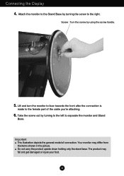
... carry the product upside down holding only the stand base. Lift and turn the monitor to face towards the front after the connection is made to the right. Important This illustration depicts the general model of the cable you're attaching. 6. The product may differ from the items shown in the picture. Screw : Turn the screw by using the screw handle. 5. A4 Connecting the Display 4.
... carry the product upside down holding only the stand base. Lift and turn the monitor to face towards the front after the connection is made to the right. Important This illustration depicts the general model of the cable you're attaching. 6. The product may differ from the items shown in the picture. Screw : Turn the screw by using the screw handle. 5. A4 Connecting the Display 4.
Owner's Manual
Page 6
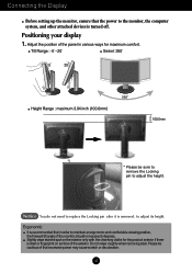
... Positioning your display 1. Tilt Range : -5˚~20˚ Swivel :350˚ Height Range : maximum 3.94 inch (100.0mm) 100.0mm * Please be cautious of that in order to maintain an ergonomic and comfortable viewing position, the forward tilt angle of the panel in various ways for the product exterior if there is removed, to adjust its height. Connecting the Display Before setting up the monitor, ensure that the power...
... Positioning your display 1. Tilt Range : -5˚~20˚ Swivel :350˚ Height Range : maximum 3.94 inch (100.0mm) 100.0mm * Please be cautious of that in order to maintain an ergonomic and comfortable viewing position, the forward tilt angle of the panel in various ways for the product exterior if there is removed, to adjust its height. Connecting the Display Before setting up the monitor, ensure that the power...
Owner's Manual
Page 7
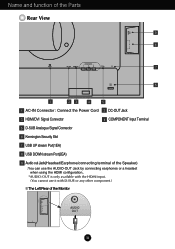
... the Parts Rear View 9 8 OUT AUDIO 2 1 COMPONENT AC-IN DC-OUT HDMI/DVI Y PB PR D-SUB 7 6 1 23 4 5 1 AC-IN Connector : Connect the Power Cord 2 DC-OUT Jack 3 HDMI/DVI Signal Connector 4 COMPONENT Input Terminal 5 D-SUB Analogue Signal Connector 6 Kensington Security Slot 7 USB UP stream Port(1EA) 8 USB DOWN stream Port(2EA) 9 Audio out Jack(Headset/Earphone/connecting terminal of the Speaker) : You can use the AUDIO-OUT Jack by connecting earphones or a headset when using the HDMI configuration.. *AUDIO...
... the Parts Rear View 9 8 OUT AUDIO 2 1 COMPONENT AC-IN DC-OUT HDMI/DVI Y PB PR D-SUB 7 6 1 23 4 5 1 AC-IN Connector : Connect the Power Cord 2 DC-OUT Jack 3 HDMI/DVI Signal Connector 4 COMPONENT Input Terminal 5 D-SUB Analogue Signal Connector 6 Kensington Security Slot 7 USB UP stream Port(1EA) 8 USB DOWN stream Port(2EA) 9 Audio out Jack(Headset/Earphone/connecting terminal of the Speaker) : You can use the AUDIO-OUT Jack by connecting earphones or a headset when using the HDMI configuration.. *AUDIO...
Owner's Manual
Page 8
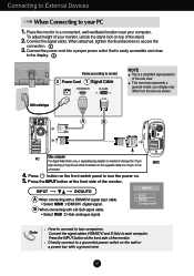
... HDMI/DVI COMPONENT Y PB PR D-SUB 1 2 AUDIO OUT Varies according to model. 2 Power Cord 1 Signal Cable NOTE This is needed to change the 15 pin high density (3 row) D-sub VGA connector on the supplied cable to a 15 pin 2 row MAC connector. 4. Connect the signal cables (HDMI/DVI and D-Sub) to secure the 3. This rear view represents a general model; B When connecting with a HDMI/DVI signal input cable. • Select HDMI : HDMI/DVI digital signal. Connect the signal cable. your computer. Press the INPUT button at the front side of the monitor. INPUT RGB HDMI...
... HDMI/DVI COMPONENT Y PB PR D-SUB 1 2 AUDIO OUT Varies according to model. 2 Power Cord 1 Signal Cable NOTE This is needed to change the 15 pin high density (3 row) D-sub VGA connector on the supplied cable to a 15 pin 2 row MAC connector. 4. Connect the signal cables (HDMI/DVI and D-Sub) to secure the 3. This rear view represents a general model; B When connecting with a HDMI/DVI signal input cable. • Select HDMI : HDMI/DVI digital signal. Connect the signal cable. your computer. Press the INPUT button at the front side of the monitor. INPUT RGB HDMI...
Owner's Manual
Page 9
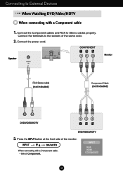
... power cord. Speaker AUDIO IN DC-OUT HDMI/DVI COMPONENT Y PB PR D-SUB 1 2 AUDIO OUT PB PR PB PR Monitor RCA-Stereo cable (not included) Component Cable (not included) DVD/VIDEO/HDTV PB PR PB PR DVD/VIDEO/HDTV 3. Connect the Component cables and RCA to Stereo cables properly. Connect the terminals to the sockets of the monitor. Press the INPUT button at the front side of the same color. 2. INPUT RGB HDMI...
... power cord. Speaker AUDIO IN DC-OUT HDMI/DVI COMPONENT Y PB PR D-SUB 1 2 AUDIO OUT PB PR PB PR Monitor RCA-Stereo cable (not included) Component Cable (not included) DVD/VIDEO/HDTV PB PR PB PR DVD/VIDEO/HDTV 3. Connect the Component cables and RCA to Stereo cables properly. Connect the terminals to the sockets of the monitor. Press the INPUT button at the front side of the same color. 2. INPUT RGB HDMI...
Owner's Manual
Page 10
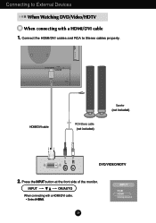
COMPONENT DC-OUT HDMI/DVI Y PB PR D-SUB OUT AUDIO 2 1 HDMI/DVI cable RCA-Stereo cable (not included) Speaker (not included) DVD/VIDEO/HDTV 2. Press the INPUT button at the front side of the monitor. A9 INPUT RGB HDMI Component Connect the HDMI/DVI cables and RCA to External Devices When Watching DVD/Video/HDTV When connecting with a HDMI/DVI cable. • Select HDMI. Connecting to Stereo cables properly. INPUT OK/AUTO When connecting with a HDMI/DVI cable 1.
COMPONENT DC-OUT HDMI/DVI Y PB PR D-SUB OUT AUDIO 2 1 HDMI/DVI cable RCA-Stereo cable (not included) Speaker (not included) DVD/VIDEO/HDTV 2. Press the INPUT button at the front side of the monitor. A9 INPUT RGB HDMI Component Connect the HDMI/DVI cables and RCA to External Devices When Watching DVD/Video/HDTV When connecting with a HDMI/DVI cable. • Select HDMI. Connecting to Stereo cables properly. INPUT OK/AUTO When connecting with a HDMI/DVI cable 1.
Owner's Manual
Page 11
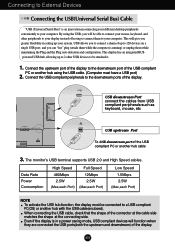
... display. USB downstream Port connect the cables from USB compliant peripherals-such as keyboard, mouse, etc OUT AUDIO 2 1 MI/DVI COMPONENT Y PB PR D-SUB USB upstream Port To USB downstream port of the USB compliant PC or another hub using the USB, you greater flexibility in connecting your different desktop peripherals conveniently to your computer. The monitor's USB terminal supports USB 2.0 and High Speed cables. Connecting to External Devices Connecting the USB(Universal Serial Bus) Cable "USB...
... display. USB downstream Port connect the cables from USB compliant peripherals-such as keyboard, mouse, etc OUT AUDIO 2 1 MI/DVI COMPONENT Y PB PR D-SUB USB upstream Port To USB downstream port of the USB compliant PC or another hub using the USB, you greater flexibility in connecting your different desktop peripherals conveniently to your computer. The monitor's USB terminal supports USB 2.0 and High Speed cables. Connecting to External Devices Connecting the USB(Universal Serial Bus) Cable "USB...
Owner's Manual
Page 12
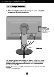
It is used to connect the components at the appropriate distance when the AUDIO-IN terminal and the speaker are plugged in as shown in the diagram. DC-OUT HDMI/DVI COMPONENT Y PB PR D-SUB 1 2 AUDIO OUT AUDIO-OUT To connect HDMI, make sure that the audio cables are connected to External Devices To arrange the cables 1. Cable Holder *The length of the cable which connects the monitor's AUDIO-OUT and the speaker's AUDIO-IN...
It is used to connect the components at the appropriate distance when the AUDIO-IN terminal and the speaker are plugged in as shown in the diagram. DC-OUT HDMI/DVI COMPONENT Y PB PR D-SUB 1 2 AUDIO OUT AUDIO-OUT To connect HDMI, make sure that the audio cables are connected to External Devices To arrange the cables 1. Cable Holder *The length of the cable which connects the monitor's AUDIO-OUT and the speaker's AUDIO-IN...

Owner's Manual
Page 13
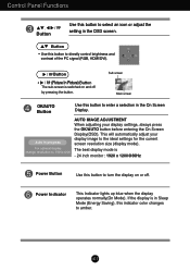
... or exit the On Screen Display. The message "Controls unlocked" should appear. INPUT OK/AUTO RGB HDMI Component : 15-pin D-SUB analogue signal : HDMI/DVI digital signal DTV SET-TOP BOX,Video,DVD : DTV SET-TOP BOX,Video,DVD INPUT RGB HDMI Component MENU Button Controls locked Controls unlocked Use this button to lock the current control settings, so that they cannot be inadvertently changed. Press and hold the MENU+ Button for several seconds. Control Panel Functions Front Panel Controls INPUT Button Select the input signal. You can unlock the OSD controls at any time...
... or exit the On Screen Display. The message "Controls unlocked" should appear. INPUT OK/AUTO RGB HDMI Component : 15-pin D-SUB analogue signal : HDMI/DVI digital signal DTV SET-TOP BOX,Video,DVD : DTV SET-TOP BOX,Video,DVD INPUT RGB HDMI Component MENU Button Controls locked Controls unlocked Use this button to lock the current control settings, so that they cannot be inadvertently changed. Press and hold the MENU+ Button for several seconds. Control Panel Functions Front Panel Controls INPUT Button Select the input signal. You can unlock the OSD controls at any time...
Owner's Manual
Page 14
.... Control Panel Functions Button Use this indicator color changes to amber. Button • (Picture In Picture) Button The sub-screen is - 24 inch monitor : 1920 x 1200@60Hz Power Button Use this button to enter a selection in the OSD screen. Sub screen Main screen OK/AUTO Button Use this button to directly control brightness and contrast of the PC signal (RGB, HDMI/DVI). Power Indicator This Indicator lights up blue when the display operates normally(On Mode). Button • Use this button to turn the display on and off . The best display mode is switched on...
.... Control Panel Functions Button Use this indicator color changes to amber. Button • (Picture In Picture) Button The sub-screen is - 24 inch monitor : 1920 x 1200@60Hz Power Button Use this button to enter a selection in the OSD screen. Sub screen Main screen OK/AUTO Button Use this button to directly control brightness and contrast of the PC signal (RGB, HDMI/DVI). Power Indicator This Indicator lights up blue when the display operates normally(On Mode). Button • Use this button to turn the display on and off . The best display mode is switched on...

Owner's Manual
Page 15
... make using the OSD. NOTE Allow the display to the desired level. 5 Accept the changes by pressing the OK/AUTO Button. 6 Exit the OSD by pressing the MENU Button. The following section is an outline of the available adjustments and selections you with the On Screen Display Control system. A14 On Screen Display (OSD) Control Adjustment Screen Adjustment Making adjustments to the image size, position and operating parameters of the display is quick and easy with the use the Buttons...
... make using the OSD. NOTE Allow the display to the desired level. 5 Accept the changes by pressing the OK/AUTO Button. 6 Exit the OSD by pressing the MENU Button. The following section is an outline of the available adjustments and selections you with the On Screen Display Control system. A14 On Screen Display (OSD) Control Adjustment Screen Adjustment Making adjustments to the image size, position and operating parameters of the display is quick and easy with the use the Buttons...
Owner's Manual
Page 17
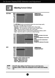
... Picture menu is set to Dynamic, Standard, Mild or Game the subsequent menus will be automatically set . • Warm : Slightly reddish white. • Normal : Slightly bluish white. • Cool : Slightly purplish white. Sharpness To adjust the clearness of the screen. Color To adjust the color to use the user-defined settings. Contrast To adjust the contrast of the screen. A16 HDMI(Video), Component input Selecting a factory setting colour set . On Screen Display(OSD) Selection and Adjustment Adjusting Screen Colour EZ Video HDMI(Video), Component input...
... Picture menu is set to Dynamic, Standard, Mild or Game the subsequent menus will be automatically set . • Warm : Slightly reddish white. • Normal : Slightly bluish white. • Cool : Slightly purplish white. Sharpness To adjust the clearness of the screen. Color To adjust the color to use the user-defined settings. Contrast To adjust the contrast of the screen. A16 HDMI(Video), Component input Selecting a factory setting colour set . On Screen Display(OSD) Selection and Adjustment Adjusting Screen Colour EZ Video HDMI(Video), Component input...
Owner's Manual
Page 19
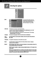
... monitor cannot be adjusted with PC by connecting communication between PC and monitor when DDC/CI is OFF. In order to lock the OSD screen adjustment, set the power indicator on the front side of the product to adjust and setup detailed functions on PC instead of the OSD menu screen. On Screen Display(OSD) Selection and Adjustment Selecting the options Input Input Child lock Language Power indicator Transparency Reset DDC-CI Input Child lock Language Power indicator Transparency Reset...
... monitor cannot be adjusted with PC by connecting communication between PC and monitor when DDC/CI is OFF. In order to lock the OSD screen adjustment, set the power indicator on the front side of the product to adjust and setup detailed functions on PC instead of the OSD menu screen. On Screen Display(OSD) Selection and Adjustment Selecting the options Input Input Child lock Language Power indicator Transparency Reset DDC-CI Input Child lock Language Power indicator Transparency Reset...

Owner's Manual
Page 23
... the screen? See the 'Specifications' section of the diplay's horizontal or vertical frequency range. A22 power indicator blue or green? Check the signal cable and try again. No image appears G Is the power cord of the • Check and see a "Controls locked" message on and the • Adjust the brightness and the contrast. G Is the power indicator amber? • If the display is connected display connected? G Do you see "Controls locked" when you see if the power cord is in power saving mode...
... the screen? See the 'Specifications' section of the diplay's horizontal or vertical frequency range. A22 power indicator blue or green? Check the signal cable and try again. No image appears G Is the power cord of the • Check and see a "Controls locked" message on and the • Adjust the brightness and the contrast. G Is the power indicator amber? • If the display is connected display connected? G Do you see "Controls locked" when you see if the power cord is in power saving mode...
Owner's Manual
Page 24
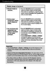
... horizontal noise appearing in the on screen display. • Check Control Panel --> Display --> Settings and adjust the display to the recommended resolution or adjust the display image to the ideal setting. If the input resolution is incorrect. • Press the OK/AUTO button to automatically adjust your display image to the ideal setting. Troubleshooting Display image is incorrect G Display Position is not 16:10 (for Recommending Optimal Resolution : The aspect ratio is 16:10. If the results are unsatisfactory, adjust the image position using...
... horizontal noise appearing in the on screen display. • Check Control Panel --> Display --> Settings and adjust the display to the recommended resolution or adjust the display image to the ideal setting. If the input resolution is incorrect. • Press the OK/AUTO button to automatically adjust your display image to the ideal setting. Troubleshooting Display image is incorrect G Display Position is not 16:10 (for Recommending Optimal Resolution : The aspect ratio is 16:10. If the results are unsatisfactory, adjust the image position using...
Owner's Manual
Page 25
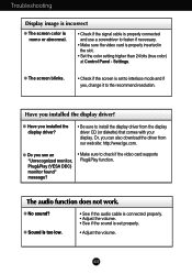
... not work. Troubleshooting Display image is incorrect G The screen color is mono or abnormal. • Check if the signal cable is properly connected and use a screwdriver to check if the video card supports Plug&Play function. G Do you can also download the driver from the display driver CD (or diskette) that comes with your display. G Sound is too low. • See if the audio cable is connected properly. • Adjust the volume. • See if the sound is set...
... not work. Troubleshooting Display image is incorrect G The screen color is mono or abnormal. • Check if the signal cable is properly connected and use a screwdriver to check if the video card supports Plug&Play function. G Do you can also download the driver from the display driver CD (or diskette) that comes with your display. G Sound is too low. • See if the audio cable is connected properly. • Adjust the volume. • See if the sound is set...
Owner's Manual
Page 26
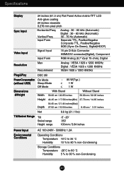
... TTL, Positive/Negative Composite TTL, Positive/Negative SOG (Sync On Green), Digital(HDCP) Signal Input 15 pin D-Sub Connector HDMI/DVI connector(Digital), Component Input Form RGB Analog (0.7 Vp-p/ 75 ohm), Digital Resolution Max Recommend Analog : VESA 1920 x 1200 @60Hz Digital : VESA 1920 x 1200 @60Hz VESA 1920 x 1200 @60Hz Plug&Play DDC 2B PowerConsumption On Mode (without USB) Sleep Mode Off Mode : 85 W(Typ.) ≤ 1W ≤ 1W Dimensions &Weight Width Height With Stand 56.00 cm / 22.05 inches 44...
... TTL, Positive/Negative Composite TTL, Positive/Negative SOG (Sync On Green), Digital(HDCP) Signal Input 15 pin D-Sub Connector HDMI/DVI connector(Digital), Component Input Form RGB Analog (0.7 Vp-p/ 75 ohm), Digital Resolution Max Recommend Analog : VESA 1920 x 1200 @60Hz Digital : VESA 1920 x 1200 @60Hz VESA 1920 x 1200 @60Hz Plug&Play DDC 2B PowerConsumption On Mode (without USB) Sleep Mode Off Mode : 85 W(Typ.) ≤ 1W ≤ 1W Dimensions &Weight Width Height With Stand 56.00 cm / 22.05 inches 44...
Owner's Manual
Page 30
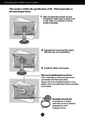
... use of the Wall mount plate or the interchange device. 1. Please refer to avoid surface damage. OUT AUDIO 2 1 DC-OUT HDMI/DVI COMPONENT Y PB PR D-SUB 2. A29 Kensington Security Slot Connected to a locking cable that can be purchased separately at most computer stores. Install the Wall mount plate. Installing the Wall mount plate This monitor satisfies the specifications of a screwdriver. Wall mount plate(Separate purchase) This is stand-type or wall mount...
... use of the Wall mount plate or the interchange device. 1. Please refer to avoid surface damage. OUT AUDIO 2 1 DC-OUT HDMI/DVI COMPONENT Y PB PR D-SUB 2. A29 Kensington Security Slot Connected to a locking cable that can be purchased separately at most computer stores. Install the Wall mount plate. Installing the Wall mount plate This monitor satisfies the specifications of a screwdriver. Wall mount plate(Separate purchase) This is stand-type or wall mount...


