Owner's Manual (English)
Page 4
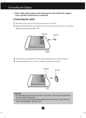
...items shown in the picture. A3 Your monitor may fall and get damaged or injure your foot. Do not carry the product upside down holding only the stand base. Once assembled take the monitor up the monitor, ensure that the power to the monitor, the computer system, and other attached ...devices is turned off. Place the monitor with its front facing downward on a soft cloth. 2. Connecting the stand 1. ...
...items shown in the picture. A3 Your monitor may fall and get damaged or injure your foot. Do not carry the product upside down holding only the stand base. Once assembled take the monitor up the monitor, ensure that the power to the monitor, the computer system, and other attached ...devices is turned off. Place the monitor with its front facing downward on a soft cloth. 2. Connecting the stand 1. ...
Owner's Manual (English)
Page 5
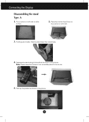
Pushing Latch inside, Take the stand base from stand body. 4. A4 Place the monitor face Down on aflat surface. 2. A 1. Pack up the product as shown in the picture. Put a cushion or soft cloth on the cushion or soft cloth. 3. Connecting the Display Disassembling the stand Type. Note: Please keep the 4 screws in the picture. Separate the stand using a screwdriver as shown in an accessible place for future use. 5.
Pushing Latch inside, Take the stand base from stand body. 4. A4 Place the monitor face Down on aflat surface. 2. A 1. Pack up the product as shown in the picture. Put a cushion or soft cloth on the cushion or soft cloth. 3. Connecting the Display Disassembling the stand Type. Note: Please keep the 4 screws in the picture. Separate the stand using a screwdriver as shown in an accessible place for future use. 5.
Owner's Manual (English)
Page 6
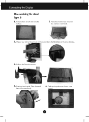
Connecting the Display Disassembling the stand Type. A5 Change your hold on the product as shown in the arrow direction. 4. Place the monitor face Down on aflat surface. 2. B 1. Pull out the Stand to remove. 5. Pushing Latch inside, Take the stand base from stand body. 6. Pack up the product as it follows and turn the Stand Base in the picture. Put a cushion or soft cloth on the cushion or soft cloth. 3.
Connecting the Display Disassembling the stand Type. A5 Change your hold on the product as shown in the arrow direction. 4. Place the monitor face Down on aflat surface. 2. B 1. Pull out the Stand to remove. 5. Pushing Latch inside, Take the stand base from stand body. 6. Pack up the product as it follows and turn the Stand Base in the picture. Put a cushion or soft cloth on the cushion or soft cloth. 3.
Owner's Manual (English)
Page 7
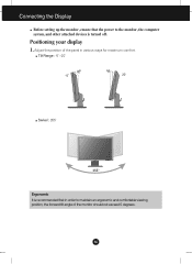
A6 Tilt Range : -5˚~20˚ 20 Swivel : 355˚ Ergonomic It is turned off. Positioning your display 1. Adjust the position of the monitor should not exceed 5 degrees. Connecting the Display Before setting up the monitor, ensure that the power to the monitor, the computer system, and other attached devices is recommended that in order to maintain an ergonomic and comfortable viewing position, the forward tilt angle of the panel in various ways for maximum comfort.
A6 Tilt Range : -5˚~20˚ 20 Swivel : 355˚ Ergonomic It is turned off. Positioning your display 1. Adjust the position of the monitor should not exceed 5 degrees. Connecting the Display Before setting up the monitor, ensure that the power to the monitor, the computer system, and other attached devices is recommended that in order to maintain an ergonomic and comfortable viewing position, the forward tilt angle of the panel in various ways for maximum comfort.
Owner's Manual (English)
Page 8
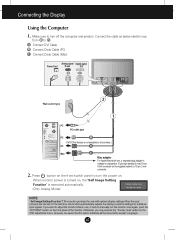
... not available in use , a separate plug adapter is needed to change the 15 pin high density (3 row) D-sub VGA connector on . When monitor power is executed automatically. (Only Analog Mode) NOTE ' Self Image Setting Function'? However, be aware that this option initializes all countries.) PC MAC ... 'Self Image Setting Function' is turned on the front switch panel to a 15 pin 2 row connector. 2. Otherwise, you want to adjust the monitor while in all the menu items except 'Language'. Connecting the Display Using the Computer 1. Connect the cable as below sketch map form 1 to optimal ...
... not available in use , a separate plug adapter is needed to change the 15 pin high density (3 row) D-sub VGA connector on . When monitor power is executed automatically. (Only Analog Mode) NOTE ' Self Image Setting Function'? However, be aware that this option initializes all countries.) PC MAC ... 'Self Image Setting Function' is turned on the front switch panel to a 15 pin 2 row connector. 2. Otherwise, you want to adjust the monitor while in all the menu items except 'Language'. Connecting the Display Using the Computer 1. Connect the cable as below sketch map form 1 to optimal ...
Owner's Manual (English)
Page 10
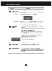
... Display. AUTO/SET Button Use this button to the ideal settings for the current screen resolution size (display mode). If the display is 22 inch monitor : 1680 x 1050 Power Button Use this button to the display. Power Indicator This Indicator lights up blue when the display operates normally(On Mode). This...
... Display. AUTO/SET Button Use this button to the ideal settings for the current screen resolution size (display mode). If the display is 22 inch monitor : 1680 x 1050 Power Button Use this button to the display. Power Indicator This Indicator lights up blue when the display operates normally(On Mode). This...
Owner's Manual (English)
Page 13
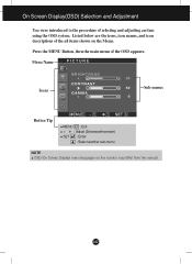
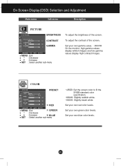
On Screen Display(OSD) Selection and Adjustment You were introduced to the procedure of the OSD appears. A12 Press the MENU Button, then the main menu of selecting and adjusting an item using the OSD system. Menu Name PICTURE Icons Sub-menus Button Tip MENU : Exit - + : Adjust (Decrease/Increase) SET : Enter : Select another sub-menu NOTE OSD (On Screen Display) menu languages on the Menu. Listed below are the icons, icon names, and icon descriptions of the all items shown on the monitor may differ from the manual.
On Screen Display(OSD) Selection and Adjustment You were introduced to the procedure of the OSD appears. A12 Press the MENU Button, then the main menu of selecting and adjusting an item using the OSD system. Menu Name PICTURE Icons Sub-menus Button Tip MENU : Exit - + : Adjust (Decrease/Increase) SET : Enter : Select another sub-menu NOTE OSD (On Screen Display) menu languages on the Menu. Listed below are the icons, icon names, and icon descriptions of the all items shown on the monitor may differ from the manual.
Owner's Manual (English)
Page 14
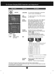
To adjust the contrast of the screen. Set your own gamma value. : -50/0/50 On the monitor, high gamma values display whitish images and low gamma values display high contrast images. A13 COLOR COLOR PRESET RED MENU : Exit GREEN - : Decrease + : Increase BLUE ...
To adjust the contrast of the screen. Set your own gamma value. : -50/0/50 On the monitor, high gamma values display whitish images and low gamma values display high contrast images. A13 COLOR COLOR PRESET RED MENU : Exit GREEN - : Decrease + : Increase BLUE ...
Owner's Manual (English)
Page 16
..., perform the white balance function again. POWER INDICATOR ARC Use this does not improve the screen image, restore the factory default settings. The 22 inch monitor is different the required specifications, the color level may deteriorate due to video signal distortion. Using this function when white and black colors are displayed...
..., perform the white balance function again. POWER INDICATOR ARC Use this does not improve the screen image, restore the factory default settings. The 22 inch monitor is different the required specifications, the color level may deteriorate due to video signal distortion. Using this function when white and black colors are displayed...
Owner's Manual (English)
Page 17
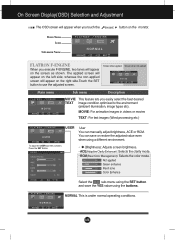
The applied screen will appear on the left side, whereas the non-applied screen will appear on the monitor. On Screen Display(OSD) Selection and Adjustment The OSD screen will appear when you touch the Menu Name Icons Sub-menu Name button on the ...
The applied screen will appear on the left side, whereas the non-applied screen will appear on the monitor. On Screen Display(OSD) Selection and Adjustment The OSD screen will appear when you touch the Menu Name Icons Sub-menu Name button on the ...
Owner's Manual (English)
Page 20
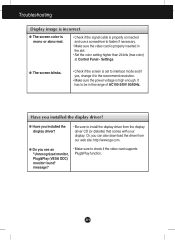
... properly inserted in the range of AC100-240V 50/60Hz. A19 Have you installed the display driver? ● Have you see an "Unrecognized monitor, Plug&Play (VESA DDC) monitor found" message? • Make sure to install the display driver from our web site: http://www.lge.com. ● Do you installed the...
... properly inserted in the range of AC100-240V 50/60Hz. A19 Have you installed the display driver? ● Have you see an "Unrecognized monitor, Plug&Play (VESA DDC) monitor found" message? • Make sure to install the display driver from our web site: http://www.lge.com. ● Do you installed the...
Owner's Manual (English)
Page 23
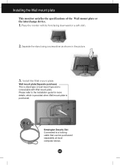
Installing the Wall mount plate This monitor satisfies the specifications of the Wall mount plate or the interchange device. 1. Wall mount plate(Separate purchase) This is stand-type or wall mount type ... installation guide for more details, which is provided when Wall mount plate is connectable with its front facing downward on a soft cloth. 2. A22 Place the monitor with Wall mount plate. Separate the stand using a screwdriver as shown in the picture. .3 Install the Wall mount plate. Please refer to a locking cable that...
Installing the Wall mount plate This monitor satisfies the specifications of the Wall mount plate or the interchange device. 1. Wall mount plate(Separate purchase) This is stand-type or wall mount type ... installation guide for more details, which is provided when Wall mount plate is connectable with its front facing downward on a soft cloth. 2. A22 Place the monitor with Wall mount plate. Separate the stand using a screwdriver as shown in the picture. .3 Install the Wall mount plate. Please refer to a locking cable that...


