User Guide
Page 1
User's Guide L1750S L1950S L1751S L1951S L1750SQ L1950SQ L1751SQ L1951SQ Make sure to your dealer when you require service. See the label attached on the back cover and quote this information to read the Important Precautions before using the product. Keep the User's Guide(CD) in an accessible place for furture reference.
User's Guide L1750S L1950S L1751S L1951S L1750SQ L1950SQ L1751SQ L1951SQ Make sure to your dealer when you require service. See the label attached on the back cover and quote this information to read the Important Precautions before using the product. Keep the User's Guide(CD) in an accessible place for furture reference.
User Guide
Page 2
... manufacturer or the nearest authorized repair service provider for replacement. The power supply cord is easily accessible after installation. Operate the display only from a power source indicated in potential eletrical shock or fire hazards. Important Precautions This unit has been engineered and manufactured to ensure your personal safety, however improper use another power cord, make sure that it from the wall outlet. There are Dangerous...
... manufacturer or the nearest authorized repair service provider for replacement. The power supply cord is easily accessible after installation. Operate the display only from a power source indicated in potential eletrical shock or fire hazards. Important Precautions This unit has been engineered and manufactured to ensure your personal safety, however improper use another power cord, make sure that it from the wall outlet. There are Dangerous...
User Guide
Page 3
... the display in a built-in a fire hazard. Do not use an aerosol directly on the display screen because over a radiator or heat source. Important Precautions On Installation Do not allow the release of heat generated during operation. On Repacking Do not throw away the carton and packing materials. On Cleaning Unplug the display before cleaning the face of the fixed-resolution LCD panel.
... the display in a built-in a fire hazard. Do not use an aerosol directly on the display screen because over a radiator or heat source. Important Precautions On Installation Do not allow the release of heat generated during operation. On Repacking Do not throw away the carton and packing materials. On Cleaning Unplug the display before cleaning the face of the fixed-resolution LCD panel.
User Guide
Page 4
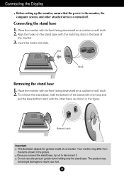
... the items shown in the picture. Align the hooks on a cushion or soft cloth. 2. To remove the stand base, hold the bottom of connection. Connecting the Display Before setting up the monitor, ensure that the power to disconnect it. Slot Hook Removing the stand base 1. Insert the hooks into slots. A3 Do not carry the product upside down holding only the stand base. Your monitor may fall and get...
... the items shown in the picture. Align the hooks on a cushion or soft cloth. 2. To remove the stand base, hold the bottom of connection. Connecting the Display Before setting up the monitor, ensure that the power to disconnect it. Slot Hook Removing the stand base 1. Insert the hooks into slots. A3 Do not carry the product upside down holding only the stand base. Your monitor may fall and get...
User Guide
Page 5
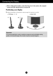
Tilt Range : -5˚~20˚ Swivel :350˚ Ergonomic It is turned off. Adjust the position of the panel in order to the monitor, the computer system, and other attached devices is recommended that in various ways for maximum comfort. Positioning your display 1. A4 Connecting the Display Before setting up the monitor, ensure that the power to maintain an ergonomic and comfortable viewing position, the forward tilt angle of the monitor should not exceed 5 degrees.
Tilt Range : -5˚~20˚ Swivel :350˚ Ergonomic It is turned off. Adjust the position of the panel in order to the monitor, the computer system, and other attached devices is recommended that in various ways for maximum comfort. Positioning your display 1. A4 Connecting the Display Before setting up the monitor, ensure that the power to maintain an ergonomic and comfortable viewing position, the forward tilt angle of the monitor should not exceed 5 degrees.
User Guide
Page 6
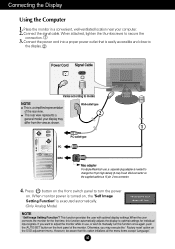
... use , a separate plug adapter is executed automatically. (Only Analog Mode) NOTE ' Self Image Setting Function'? Otherwise, you want to a 15 pin 2 row connector. 4. A5 Connect the signal cable. Power Cord Signal Cable Varies according to secure the connection. 3. Press button on the front switch panel to turn the power on the supplied cable to adjust the monitor while in a convenient, well-ventilated location near your display may execute the ' Factory reset' option on the front panel of the rear view...
... use , a separate plug adapter is executed automatically. (Only Analog Mode) NOTE ' Self Image Setting Function'? Otherwise, you want to a 15 pin 2 row connector. 4. A5 Connect the signal cable. Power Cord Signal Cable Varies according to secure the connection. 3. Press button on the front switch panel to turn the power on the supplied cable to adjust the monitor while in a convenient, well-ventilated location near your display may execute the ' Factory reset' option on the front panel of the rear view...
User Guide
Page 7
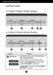
OSD LOCKED/UNLOCKED This function allows you to enter or exit the On Screen Display. The message "OSD UNLOCKED" should appear. Control Panel Functions Front Panel Controls Control MENU Button Function Use this button to lock the current control settings, so that they cannot be inadvertently changed. Press and hold the MENU button for 5 seconds. A6 The message "OSD LOCKED" should appear. You can unlock the OSD controls at any time by pushing the MENU button for 5 seconds.
OSD LOCKED/UNLOCKED This function allows you to enter or exit the On Screen Display. The message "OSD UNLOCKED" should appear. Control Panel Functions Front Panel Controls Control MENU Button Function Use this button to lock the current control settings, so that they cannot be inadvertently changed. Press and hold the MENU button for 5 seconds. A6 The message "OSD LOCKED" should appear. You can unlock the OSD controls at any time by pushing the MENU button for 5 seconds.
User Guide
Page 8
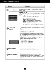
... Panel Functions Control Function - + Buttons Use these buttons to the ideal settings for the current screen resolution size (display mode). The best display mode is 17 inch monitor : 1280x1024 19 inch monitor : 1280x1024 Power Button Use this indicator color changes to amber. If the display is under normal operating conditions AUTO/SET Button Use this button to turn the display on or off. This will automatically adjust your display settings, always press the AUTO/SET button before entering the On Screen Display(OSD). Power Indicator This Indicator lights up green...
... Panel Functions Control Function - + Buttons Use these buttons to the ideal settings for the current screen resolution size (display mode). The best display mode is 17 inch monitor : 1280x1024 19 inch monitor : 1280x1024 Power Button Use this indicator color changes to amber. If the display is under normal operating conditions AUTO/SET Button Use this button to turn the display on or off. This will automatically adjust your display settings, always press the AUTO/SET button before entering the On Screen Display(OSD). Power Indicator This Indicator lights up green...

User Guide
Page 9
... Screen Display (OSD) Control Adjustment Screen Adjustment Making adjustments to the image size, position and operating parameters of the available adjustments and selections you can make adjustments in the On Screen Display, follow these steps: Press the MENU Button, then the main menu of the controls. The following section is an outline of the display is given below to familiarize you want becomes highlighted, press the AUTO/SET Button. To make using the OSD. A8 Use the - / + Buttons to adjust the image...
... Screen Display (OSD) Control Adjustment Screen Adjustment Making adjustments to the image size, position and operating parameters of the available adjustments and selections you can make adjustments in the On Screen Display, follow these steps: Press the MENU Button, then the main menu of the controls. The following section is an outline of the display is given below to familiarize you want becomes highlighted, press the AUTO/SET Button. To make using the OSD. A8 Use the - / + Buttons to adjust the image...
User Guide
Page 10
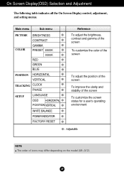
... menu PICTURE BRIGHTNESS CONTRAST COLOR GAMMA PRESET 6500K 9300K RED GREEN BLUE POSITION HORIZONTAL VERTICAL TRACKING CLOCK PHASE SETUP LANGUAGE OSD HORIZONTAL POSITION VERTICAL WHITE BALANCE POWER INDICATOR FACTORY RESET Reference To adjust the brightness, contrast and gamma of the screen To customize the color of the screen To adjust the position of the screen To improve the clarity and stability of the screen To customize the screen status for a user's operating environment : Adjustable NOTE The order of icons may differ depending on the model...
... menu PICTURE BRIGHTNESS CONTRAST COLOR GAMMA PRESET 6500K 9300K RED GREEN BLUE POSITION HORIZONTAL VERTICAL TRACKING CLOCK PHASE SETUP LANGUAGE OSD HORIZONTAL POSITION VERTICAL WHITE BALANCE POWER INDICATOR FACTORY RESET Reference To adjust the brightness, contrast and gamma of the screen To customize the color of the screen To adjust the position of the screen To improve the clarity and stability of the screen To customize the screen status for a user's operating environment : Adjustable NOTE The order of icons may differ depending on the model...

User Guide
Page 11
Press the MENU Button, then the main menu of selecting and adjusting an item using the OSD system. On Screen Display(OSD) Selection and Adjustment You were introduced to the procedure of the OSD appears. A10 Listed below are the icons, icon names, and icon descriptions of the all items shown on the monitor may differ from the manual. Menu Name PICTURE Icons Sub-menus Button Tip MENU : Exit - + : Adjust (Decrease/Increase) SET : Enter : Select another sub-menu NOTE OSD (On Screen Display) menu languages on the Menu.
Press the MENU Button, then the main menu of selecting and adjusting an item using the OSD system. On Screen Display(OSD) Selection and Adjustment You were introduced to the procedure of the OSD appears. A10 Listed below are the icons, icon names, and icon descriptions of the all items shown on the monitor may differ from the manual. Menu Name PICTURE Icons Sub-menus Button Tip MENU : Exit - + : Adjust (Decrease/Increase) SET : Enter : Select another sub-menu NOTE OSD (On Screen Display) menu languages on the Menu.
User Guide
Page 12
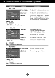
... screen. RED Set your own blue color levels. BLUE MENU : Exit +- : Decrease : Increase SET : Select another sub-menu A11 VERTICAL To move image left and right. GREEN Set your own gamma value. : -50/0/50 On the monitor, high gamma values display whitish images and low gamma values display high contrast images. To move image up and down. Set your own green color levels. On Screen Display(OSD) Selection and Adjustment Main menu PICTURE PICTURE Sub menu Description BRIGHTNESS To adjust the brightness of the screen. COLOR COLOR...
... screen. RED Set your own blue color levels. BLUE MENU : Exit +- : Decrease : Increase SET : Select another sub-menu A11 VERTICAL To move image left and right. GREEN Set your own gamma value. : -50/0/50 On the monitor, high gamma values display whitish images and low gamma values display high contrast images. To move image up and down. Set your own green color levels. On Screen Display(OSD) Selection and Adjustment Main menu PICTURE PICTURE Sub menu Description BRIGHTNESS To adjust the brightness of the screen. COLOR COLOR...
User Guide
Page 13
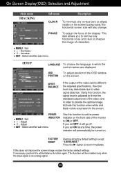
... the input signal is different the required specifications, the color level may deteriorate due to video signal distortion. PHASE To adjust the focus of the video card in order to set the power indicator on the screen background.The horizontal screen size will also change. Using this function to provide the optimal image. MENU - + SET POWER MENU : Exit +- : Adjust : Adjust INDICATOR SET : Select another sub-menu SETUP SETUP LANGUAGE To choose the language in the screen. If you set ON at any vertical bars...
... the input signal is different the required specifications, the color level may deteriorate due to video signal distortion. PHASE To adjust the focus of the video card in order to set the power indicator on the screen background.The horizontal screen size will also change. Using this function to provide the optimal image. MENU - + SET POWER MENU : Exit +- : Adjust : Adjust INDICATOR SET : Select another sub-menu SETUP SETUP LANGUAGE To choose the language in the screen. If you set ON at any vertical bars...
User Guide
Page 14
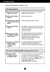
... the 'Specifications' section of this manual and configure your display is out of horizontal or vertical frequency range of the display connected? You can secure the current control settings, so that they cannot be inadvertently changed. Check and see a "OSD LOCKED" message on the screen? Is the power on ? Try to the power outlet. This message appears when the signal from the PC (video card) is not connected. Do you see a "CHECK SIGNAL CABLE" message...
... the 'Specifications' section of this manual and configure your display is out of horizontal or vertical frequency range of the display connected? You can secure the current control settings, so that they cannot be inadvertently changed. Check and see a "OSD LOCKED" message on the screen? Is the power on ? Try to the power outlet. This message appears when the signal from the PC (video card) is not connected. Do you see a "CHECK SIGNAL CABLE" message...
User Guide
Page 15
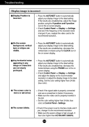
.... Check if the signal cable is set to interlace mode and if yes, change it to the recommend resolution. Make sure the video card is high enough, It has to the ideal setting. A14 Troubleshooting Display image is incorrect Display Position is mono or abnormal. Press the AUTO/SET button to automatically adjust your display image to the ideal setting. The screen color is incorrect. Set the color setting higher than AC100-240V 50/60Hz. Settings. Make sure the power voltage...
.... Check if the signal cable is set to interlace mode and if yes, change it to the recommend resolution. Make sure the video card is high enough, It has to the ideal setting. A14 Troubleshooting Display image is incorrect Display Position is mono or abnormal. Press the AUTO/SET button to automatically adjust your display image to the ideal setting. The screen color is incorrect. Set the color setting higher than AC100-240V 50/60Hz. Settings. Make sure the power voltage...
User Guide
Page 16
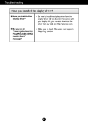
Or, you installed the display driver? A15 Do you installed the display driver? Troubleshooting Have you see an "Unrecognized monitor, Plug&Play (VESA DDC) monitor found" message? Be sure to check if the video card supports Plug&Play function. Have you can also download the driver from the display driver CD (or diskette) that comes with your display. Make sure to install the display driver from our web site: http://www.lge.com.
Or, you installed the display driver? A15 Do you installed the display driver? Troubleshooting Have you see an "Unrecognized monitor, Plug&Play (VESA DDC) monitor found" message? Be sure to check if the video card supports Plug&Play function. Have you can also download the driver from the display driver CD (or diskette) that comes with your display. Make sure to install the display driver from our web site: http://www.lge.com.
User Guide
Page 17
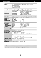
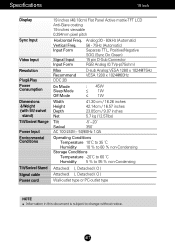
... 5 % to 95 % non-Condensing Attached( ), Detached ( O ) Attached( ), Detached ( O ) Wall-outlet type or PC-outlet type NOTE Information in this document is subject to change without notice. A16 Vertical Freq. Specifications 17 inch Display Sync Input Video Input Resolution Plug&Play Power Consumption Dimensions &Weight (with tilt/ swivel stand) Tilt/Swivel Range Power Input Environmental Conditions Tilt/Swivel Stand Signal cable Power cord 17 inches (43.2cm) Flat Panel Active matrix-TFT LCD Anti-Glare coating 17 inches viewable 0.26mm pixel pitch Horizontal Freq.
... 5 % to 95 % non-Condensing Attached( ), Detached ( O ) Attached( ), Detached ( O ) Wall-outlet type or PC-outlet type NOTE Information in this document is subject to change without notice. A16 Vertical Freq. Specifications 17 inch Display Sync Input Video Input Resolution Plug&Play Power Consumption Dimensions &Weight (with tilt/ swivel stand) Tilt/Swivel Range Power Input Environmental Conditions Tilt/Swivel Stand Signal cable Power cord 17 inches (43.2cm) Flat Panel Active matrix-TFT LCD Anti-Glare coating 17 inches viewable 0.26mm pixel pitch Horizontal Freq.
User Guide
Page 18
Specifications 19 inch Display Sync Input Video Input Resolution Plug&Play Power Consumption Dimensions &Weight (with tilt/ swivel stand) Tilt/Swivel Range Power Input Environmental Conditions Tilt/Swivel Stand Signal cable Power cord 19 inches (48.18cm) Flat Panel Active matrix-TFT LCD Anti-Glare coating 19 inches viewable 0.294mm pixel pitch Horizontal Freq. A17 Input Form Signal Input Input Form Analog:30 - 83kHz (Automatic) 56 - 75Hz (Automatic) Separate TTL, Positive/Negative SOG (Sync On Green) 15 pin D-Sub Connector RGB Analog (0.7Vp-p/75ohm) Max Recommend DDC 2B D-sub ...
Specifications 19 inch Display Sync Input Video Input Resolution Plug&Play Power Consumption Dimensions &Weight (with tilt/ swivel stand) Tilt/Swivel Range Power Input Environmental Conditions Tilt/Swivel Stand Signal cable Power cord 19 inches (48.18cm) Flat Panel Active matrix-TFT LCD Anti-Glare coating 19 inches viewable 0.294mm pixel pitch Horizontal Freq. A17 Input Form Signal Input Input Form Analog:30 - 83kHz (Automatic) 56 - 75Hz (Automatic) Separate TTL, Positive/Negative SOG (Sync On Green) 15 pin D-Sub Connector RGB Analog (0.7Vp-p/75ohm) Max Recommend DDC 2B D-sub ...

User Guide
Page 19
Specifications Preset Modes (Resolution) Display Modes (Resolution) 1 VGA 640 x 350 2 VGA 720 x 400 3 VGA 640 x 480 4 VESA 640 x 480 5 VESA 800 x 600 6 VESA 800 x 600 7 MAC 832 x 624 8 VESA 1024 x 768 9 VESA 1024 x 768 10 MAC 1152 x 870 11 VESA 1152 x 900 12 VESA 1280 x 1024 13 VESA 1280 x 1024 Horizontal Freq. (kHz) 31.469 31.468 31.469 37.500 37.879 46.875 49.725 48.363 60.023 68.681 61.805 63.981 79.976 Indicator MODE On Mode Sleep Mode Off Mode LED Color green amber Off Vertical Freq. (Hz) 70 70 60 75 60 75 75 60 75 75 65 60 75 A18
Specifications Preset Modes (Resolution) Display Modes (Resolution) 1 VGA 640 x 350 2 VGA 720 x 400 3 VGA 640 x 480 4 VESA 640 x 480 5 VESA 800 x 600 6 VESA 800 x 600 7 MAC 832 x 624 8 VESA 1024 x 768 9 VESA 1024 x 768 10 MAC 1152 x 870 11 VESA 1152 x 900 12 VESA 1280 x 1024 13 VESA 1280 x 1024 Horizontal Freq. (kHz) 31.469 31.468 31.469 37.500 37.879 46.875 49.725 48.363 60.023 68.681 61.805 63.981 79.976 Indicator MODE On Mode Sleep Mode Off Mode LED Color green amber Off Vertical Freq. (Hz) 70 70 60 75 60 75 75 60 75 75 65 60 75 A18
User Guide
Page 20
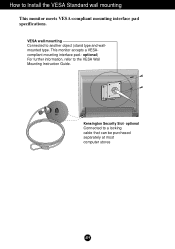
optional) For further information, refer to another object (stand type and wallmounted type. Kensington Security Slot- This monitor accepts a VESAcompliant mounting interface pad.- VESA wall mounting Connected to the VESA Wall Mounting Instruction Guide. optional Connected to Install the VESA Standard wall mounting This monitor meets VESA-compliant mounting interface pad specifications. How to a locking cable that can be purchased separately at most computer stores A19
optional) For further information, refer to another object (stand type and wallmounted type. Kensington Security Slot- This monitor accepts a VESAcompliant mounting interface pad.- VESA wall mounting Connected to the VESA Wall Mounting Instruction Guide. optional Connected to Install the VESA Standard wall mounting This monitor meets VESA-compliant mounting interface pad specifications. How to a locking cable that can be purchased separately at most computer stores A19


