
Owner's Manual
Page 2
.... Overloaded AC outlets and extension cords are frayed power cords and broken plugs. To Avoid Personal Injury : Do not place the display on the display. Keep children from the wall outlet. If you are not sure what type of power supply you have not been designed for an extended period of this display. Do not Open the Display. Use only a stand recommended by the supplier...
.... Overloaded AC outlets and extension cords are frayed power cords and broken plugs. To Avoid Personal Injury : Do not place the display on the display. Keep children from the wall outlet. If you are not sure what type of power supply you have not been designed for an extended period of this display. Do not Open the Display. Use only a stand recommended by the supplier...

Owner's Manual
Page 3
...Cover the openings with general household waste. Do not rub or strike the Active Matrix LCD with anything to rest upon or roll over the power cord, and do not place the display where the power cord is subject to obtain the best image quality for your finger for a long time as Red, Green or Blue spots on the display screen... unless proper ventilation is characteristic of the fixed-resolution LCD panel. On Disposal The fluorescent lamp used under any mode except the recommended resolution, some afterimages. Important Precautions On Installation Do not allow the release of heat generated...
...Cover the openings with general household waste. Do not rub or strike the Active Matrix LCD with anything to rest upon or roll over the power cord, and do not place the display where the power cord is subject to obtain the best image quality for your finger for a long time as Red, Green or Blue spots on the display screen... unless proper ventilation is characteristic of the fixed-resolution LCD panel. On Disposal The fluorescent lamp used under any mode except the recommended resolution, some afterimages. Important Precautions On Installation Do not allow the release of heat generated...
Owner's Manual
Page 4
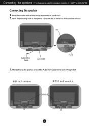
Place the monitor with its front facing downward on a soft cloth. 2. Insert the protruding hook of the speaker in the direction of the slot in the back of the product. 19 inch monitor 20.1 inch monitor A3 Slot Audio DC-In Cable Hook 3. After setting up the speaker, connect the Audio DC-In Cable to the back of the product. The feature is only for speaker models - L194WTM, L204WTM Connecting the speaker 1. Connecting the speakers -
Place the monitor with its front facing downward on a soft cloth. 2. Insert the protruding hook of the speaker in the direction of the slot in the back of the product. 19 inch monitor 20.1 inch monitor A3 Slot Audio DC-In Cable Hook 3. After setting up the speaker, connect the Audio DC-In Cable to the back of the product. The feature is only for speaker models - L194WTM, L204WTM Connecting the speaker 1. Connecting the speakers -
Owner's Manual
Page 6
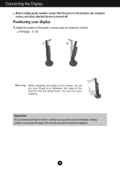
... is turned off. You can hurt your display 1. Tilt Range : -5˚~20˚ 20 Warning: When adjusting the angle of the screen, do not put your finger(s) in between the head of the monitor and the stand body. A5 Connecting the Display Before setting up the monitor, ensure that the power to maintain an ergonomic and comfortable viewing position, the forward tilt angle of the monitor should...
... is turned off. You can hurt your display 1. Tilt Range : -5˚~20˚ 20 Warning: When adjusting the angle of the screen, do not put your finger(s) in between the head of the monitor and the stand body. A5 Connecting the Display Before setting up the monitor, ensure that the power to maintain an ergonomic and comfortable viewing position, the forward tilt angle of the monitor should...
Owner's Manual
Page 7
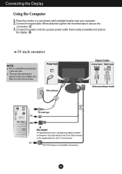
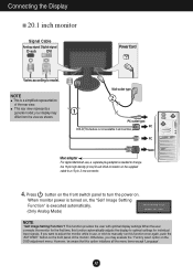
... VGA connector on the supplied cable to a 15 pin 2 row connector. your computer. 2. Connect the signal cable. PC DVI-D(This feature is not available in a convenient, well-ventilated location near your display may differ from the view as shown. Power Cord Wall-outlet type 2 1 PC-outlet type PC MAC Mac adapter For Apple Macintosh use, a separate plug adapter is a simplified representation of the rear view. Place the monitor in all countries.) Signal Cable Analog signal Digital signal D-sub DVI...
... VGA connector on the supplied cable to a 15 pin 2 row connector. your computer. 2. Connect the signal cable. PC DVI-D(This feature is not available in a convenient, well-ventilated location near your display may differ from the view as shown. Power Cord Wall-outlet type 2 1 PC-outlet type PC MAC Mac adapter For Apple Macintosh use, a separate plug adapter is a simplified representation of the rear view. Place the monitor in all countries.) Signal Cable Analog signal Digital signal D-sub DVI...
Owner's Manual
Page 8
... model; your display may execute the ' Factory reset' option on the OSD adjustment menu. Press button on the front switch panel to turn the power on the supplied cable to manually run this function once again, push the 'AUTO/SET' button on , the 'Self Image Setting Function' is turned on the front panel of the rear view. This function provides the user with optimal display settings.When the user connects the monitor for individual input signals. Wall-outlet type 2 1 PC-outlet type PC DVI...
... model; your display may execute the ' Factory reset' option on the OSD adjustment menu. Press button on the front switch panel to turn the power on the supplied cable to manually run this function once again, push the 'AUTO/SET' button on , the 'Self Image Setting Function' is turned on the front panel of the rear view. This function provides the user with optimal display settings.When the user connects the monitor for individual input signals. Wall-outlet type 2 1 PC-outlet type PC DVI...
Owner's Manual
Page 10
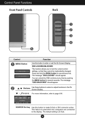
... default setting is used when two computers are connected to the display. Control Panel Functions Front Panel Controls Back Control MENU Button Function Use this button to lock the current control settings, so that they cannot be inadvertently changed. The message "OSD UNLOCKED" should appear. You can unlock the OSD controls at any time by pushing the MENU button for several seconds. A9 The message "OSD LOCKED" should appear. Press and hold the MENU button for several seconds. Buttons Use these buttons...
... default setting is used when two computers are connected to the display. Control Panel Functions Front Panel Controls Back Control MENU Button Function Use this button to lock the current control settings, so that they cannot be inadvertently changed. The message "OSD UNLOCKED" should appear. You can unlock the OSD controls at any time by pushing the MENU button for several seconds. A9 The message "OSD LOCKED" should appear. Press and hold the MENU button for several seconds. Buttons Use these buttons...
Owner's Manual
Page 11
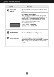
... Indicator This Indicator lights up blue when the display operates normally(On Mode). Control Panel Functions Control AUTO/SET Button Function Use this button to enter a selection in Sleep Mode (Energy Saving), this button to the ideal settings for the current screen resolution size (display mode). The best display mode is in the On Screen Display. If the display is 19 inch monitor : 1440 x 900 20.1 inch monitor : 1680 x 1050 Power Button Use this indicator color changes to amber. A10 AUTO IMAGE ADJUSTMENT When adjusting your display image to turn the display on or off...
... Indicator This Indicator lights up blue when the display operates normally(On Mode). Control Panel Functions Control AUTO/SET Button Function Use this button to enter a selection in Sleep Mode (Energy Saving), this button to the ideal settings for the current screen resolution size (display mode). The best display mode is in the On Screen Display. If the display is 19 inch monitor : 1440 x 900 20.1 inch monitor : 1680 x 1050 Power Button Use this indicator color changes to amber. A10 AUTO IMAGE ADJUSTMENT When adjusting your display image to turn the display on or off...
Owner's Manual
Page 13
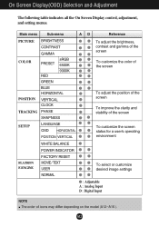
... PRESET RED sRGB 6500K 9300K POSITION GREEN BLUE HORIZONTAL VERTICAL CLOCK TRACKING PHASE SHAPNESS SETUP LANGUAGE OSD HORIZONTAL POSITION VERTICAL To adjust the brightness, contrast and gamma of the screen To customize the color of the screen To adjust the position of the screen To improve the clarity and stability of the screen To customize the screen status for a user's operating environment WHITE BALANCE POWER INDICATOR FLATRON F-ENGINE FACTORY RESET MOVIE / TEXT USER NORMAL To select or customize desired image settings : Adjustable A : Analog Input D : Digital Input NOTE...
... PRESET RED sRGB 6500K 9300K POSITION GREEN BLUE HORIZONTAL VERTICAL CLOCK TRACKING PHASE SHAPNESS SETUP LANGUAGE OSD HORIZONTAL POSITION VERTICAL To adjust the brightness, contrast and gamma of the screen To customize the color of the screen To adjust the position of the screen To improve the clarity and stability of the screen To customize the screen status for a user's operating environment WHITE BALANCE POWER INDICATOR FLATRON F-ENGINE FACTORY RESET MOVIE / TEXT USER NORMAL To select or customize desired image settings : Adjustable A : Analog Input D : Digital Input NOTE...
Owner's Manual
Page 14
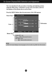
On Screen Display(OSD) Selection and Adjustment You were introduced to the procedure of the OSD appears. Menu Name PICTURE Icons Sub-menus Button Tip MENU : Exit : Adjust (Decrease/Increase) SET : Enter : Select another sub-menu NOTE OSD (On Screen Display) menu languages on the Menu. Press the MENU Button, then the main menu of selecting and adjusting an item using the OSD system. Listed below are the icons, icon names, and icon descriptions of the all items shown on the monitor may differ from the manual. A13
On Screen Display(OSD) Selection and Adjustment You were introduced to the procedure of the OSD appears. Menu Name PICTURE Icons Sub-menus Button Tip MENU : Exit : Adjust (Decrease/Increase) SET : Enter : Select another sub-menu NOTE OSD (On Screen Display) menu languages on the Menu. Press the MENU Button, then the main menu of selecting and adjusting an item using the OSD system. Listed below are the icons, icon names, and icon descriptions of the all items shown on the monitor may differ from the manual. A13
Owner's Manual
Page 15
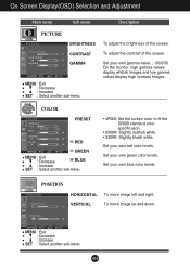
... white. VERTICAL To move image left and right. Set your own gamma value. : -50/0/50 On the monitor, high gamma values display whitish images and low gamma values display high contrast images. POSITION POSITION HORIZONTAL To move image up and down. Set your own blue color levels. COLOR COLOR PRESET RED GREEN MENU : Exit : Decrease BLUE : Increase SET : Select another sub-menu To adjust the brightness of the screen. Set your own red color levels. MENU : Exit : Decrease : Increase SET : Select another sub-menu...
... white. VERTICAL To move image left and right. Set your own gamma value. : -50/0/50 On the monitor, high gamma values display whitish images and low gamma values display high contrast images. POSITION POSITION HORIZONTAL To move image up and down. Set your own blue color levels. COLOR COLOR PRESET RED GREEN MENU : Exit : Decrease BLUE : Increase SET : Select another sub-menu To adjust the brightness of the screen. Set your own red color levels. MENU : Exit : Decrease : Increase SET : Select another sub-menu...
Owner's Manual
Page 16
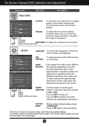
... function to set the power indicator on . POWER MENU : Exit : Adjust INDICATOR : Adjust SET : Select another sub-menu SETUP SETUP LANGUAGE To choose the language in which the control names are present in order to remove any vertical bars or stripes visible on the screen. If you set OFF, it will also change. If necessary, perform the white balance function again. FACTORY RESET Restore all factory default settings except "LANGUAGE." A15 OSD To adjust position of the video card is...
... function to set the power indicator on . POWER MENU : Exit : Adjust INDICATOR : Adjust SET : Select another sub-menu SETUP SETUP LANGUAGE To choose the language in which the control names are present in order to remove any vertical bars or stripes visible on the screen. If you set OFF, it will also change. If necessary, perform the white balance function again. FACTORY RESET Restore all factory default settings except "LANGUAGE." A15 OSD To adjust position of the video card is...
Owner's Manual
Page 17
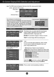
... text images (Word processing etc.) USER User You can save or restore the adjusted value even when using a different envir To adjust the USER sub-menu function, Press the SET Button ... (Brightness): Adjusts screen brightness. ...ACE(Adaptive Clarity Enhancer): Selects the clarity mode. ...RCM(Real Color Management): Selects the color mode. 0 Not applied 1 Green enhance 2 Flesh tone 3 Color Enhance Select the SAVE sub-menu using the SET button and save the YES value using the buttons. On Screen Display(OSD) Selection and Adjustment The OSD screen...
... text images (Word processing etc.) USER User You can save or restore the adjusted value even when using a different envir To adjust the USER sub-menu function, Press the SET Button ... (Brightness): Adjusts screen brightness. ...ACE(Adaptive Clarity Enhancer): Selects the clarity mode. ...RCM(Real Color Management): Selects the color mode. 0 Not applied 1 Green enhance 2 Flesh tone 3 Color Enhance Select the SAVE sub-menu using the SET button and save the YES value using the buttons. On Screen Display(OSD) Selection and Adjustment The OSD screen...
Owner's Manual
Page 18
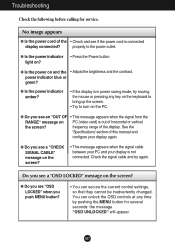
... be inadvertently changed. A17 light on and the • Adjust the brightness and the contrast. G Is the power indicator amber? • If the display is connected display connected? See the 'Specifications' section of the display. G Do you see "OSD LOCKED" when you see a "OSD LOCKED" message on the screen? frequency range of this manual and configure your display is out of the • Check and see a "CHECK SIGNAL CABLE" message on PC (video card) is not connected. Troubleshooting Check the...
... be inadvertently changed. A17 light on and the • Adjust the brightness and the contrast. G Is the power indicator amber? • If the display is connected display connected? See the 'Specifications' section of the display. G Do you see "OSD LOCKED" when you see a "OSD LOCKED" message on the screen? frequency range of this manual and configure your display is out of the • Check and see a "CHECK SIGNAL CABLE" message on PC (video card) is not connected. Troubleshooting Check the...
Owner's Manual
Page 19
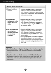
... the video card performance. If the results are unsatisfactory, decrease the horizontal bars using the CLOCK icon in any image or characters are visible. • Press the AUTO/SET button to automatically adjust your display image to the ideal setting. Important Check Control Panel --> Display --> Settings and see if the frequency or the resolution were changed. If the results are unsatisfactory, adjust the image position using the H position and V position icon in the on screen display. Troubleshooting Display image is incorrect G Display Position...
... the video card performance. If the results are unsatisfactory, decrease the horizontal bars using the CLOCK icon in any image or characters are visible. • Press the AUTO/SET button to automatically adjust your display image to the ideal setting. Important Check Control Panel --> Display --> Settings and see if the frequency or the resolution were changed. If the results are unsatisfactory, adjust the image position using the H position and V position icon in the on screen display. Troubleshooting Display image is incorrect G Display Position...
Owner's Manual
Page 20
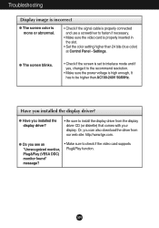
Troubleshooting Display image is incorrect G The screen color is mono or abnormal. • Check if the signal cable is properly connected and use a screwdriver to fasten if necessary. • Make sure the video card is high enough, It has to be higher than 24 bits (true color) at Control Panel - Or, you see an "Unrecognized monitor, Plug&Play (VESA DDC) monitor found" message? • Make sure to check if the video card supports Plug&Play function. G Do...
Troubleshooting Display image is incorrect G The screen color is mono or abnormal. • Check if the signal cable is properly connected and use a screwdriver to fasten if necessary. • Make sure the video card is high enough, It has to be higher than 24 bits (true color) at Control Panel - Or, you see an "Unrecognized monitor, Plug&Play (VESA DDC) monitor found" message? • Make sure to check if the video card supports Plug&Play function. G Do...

Owner's Manual
Page 21
... ˚C Humidity 5 % to 90 % non-Condensing Attached ( ), Detached ( O ) Attached ( ), Detached ( O ) Wall-outlet type or PC-outlet type NOTE Information in this document is subject to change without notice. Specifications L194WT/L194WTQ/L194WTX Display Sync Input Video Input Resolution Plug&Play Power Consumption Dimensions &Weight Tilt Range Power Input Environmental Conditions Stand Base Signal cable Power cord 19 inches (48.2 cm) Flat Panel Active matrix-TFT LCD Anti-Glare coating 19 inches viewable 0.2835 mm pixel pitch Horizontal Freq. A20 Vertical Freq.
... ˚C Humidity 5 % to 90 % non-Condensing Attached ( ), Detached ( O ) Attached ( ), Detached ( O ) Wall-outlet type or PC-outlet type NOTE Information in this document is subject to change without notice. Specifications L194WT/L194WTQ/L194WTX Display Sync Input Video Input Resolution Plug&Play Power Consumption Dimensions &Weight Tilt Range Power Input Environmental Conditions Stand Base Signal cable Power cord 19 inches (48.2 cm) Flat Panel Active matrix-TFT LCD Anti-Glare coating 19 inches viewable 0.2835 mm pixel pitch Horizontal Freq. A20 Vertical Freq.
Owner's Manual
Page 22
... 5 % to 90 % non-Condensing Attached ( ), Detached ( O ) Attached ( ), Detached ( O ) Wall-outlet type or PC-outlet type RMS Audio Output 1W+1W(R+L) Input Sensitivity 0.7Vrms Speaker Impedance 16Ω NOTE Information in this document is subject to change without speaker) Dimensions &Weight Tilt Range Power Input Environmental Conditions Stand Base Signal cable Power cord Audio 19 inches (48.2 cm) Flat Panel Active matrix-TFT LCD Anti-Glare coating 19 inches viewable 0.2835 mm pixel pitch Horizontal Freq.
... 5 % to 90 % non-Condensing Attached ( ), Detached ( O ) Attached ( ), Detached ( O ) Wall-outlet type or PC-outlet type RMS Audio Output 1W+1W(R+L) Input Sensitivity 0.7Vrms Speaker Impedance 16Ω NOTE Information in this document is subject to change without speaker) Dimensions &Weight Tilt Range Power Input Environmental Conditions Stand Base Signal cable Power cord Audio 19 inches (48.2 cm) Flat Panel Active matrix-TFT LCD Anti-Glare coating 19 inches viewable 0.2835 mm pixel pitch Horizontal Freq.

Owner's Manual
Page 23
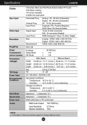
...subject to change without notice. Input Form Analog : 30 - 83 kHz (Automatic) Digital : 30 - 83 kHz (Automatic) 56 - 75 Hz (Automatic) Separate TTL, Positive/Negative SOG (Sync On Green) Digital Signal Input Input Form 15 pin D-Sub Connector DVI - Specifications L204WT/L204WTQ/L204WTX Display Sync Input Video Input Resolution Plug&Play Power Consumption Dimensions &Weight Tilt Range Power Input Environmental Conditions Stand Base Signal cable Power cord 20.1 inches (51.1 cm) Flat Panel Active matrix-TFT LCD Anti-Glare coating 20.1 inches viewable 0.258 mm pixel pitch Horizontal Freq.
...subject to change without notice. Input Form Analog : 30 - 83 kHz (Automatic) Digital : 30 - 83 kHz (Automatic) 56 - 75 Hz (Automatic) Separate TTL, Positive/Negative SOG (Sync On Green) Digital Signal Input Input Form 15 pin D-Sub Connector DVI - Specifications L204WT/L204WTQ/L204WTX Display Sync Input Video Input Resolution Plug&Play Power Consumption Dimensions &Weight Tilt Range Power Input Environmental Conditions Stand Base Signal cable Power cord 20.1 inches (51.1 cm) Flat Panel Active matrix-TFT LCD Anti-Glare coating 20.1 inches viewable 0.258 mm pixel pitch Horizontal Freq.

Owner's Manual
Page 24
... to change without speaker) Dimensions &Weight Tilt Range Power Input Environmental Conditions Stand Base Signal cable Power cord Audio 20.1 inches (51.1 cm) Flat Panel Active matrix-TFT LCD Anti-Glare coating 20.1 inches viewable 0.258 mm pixel pitch Horizontal Freq. Specifications L204WTM Display Sync Input Video Input Resolution Plug&Play Power Consumption (without notice. Input Form Signal Input Input Form Analog : 30 - 83 kHz (Automatic) Digital : 30 - 83 kHz (Automatic) 56 - 75 Hz (Automatic) Separate TTL, Positive/Negative SOG (Sync On Green) Digital 15 pin D-Sub Connector DVI...
... to change without speaker) Dimensions &Weight Tilt Range Power Input Environmental Conditions Stand Base Signal cable Power cord Audio 20.1 inches (51.1 cm) Flat Panel Active matrix-TFT LCD Anti-Glare coating 20.1 inches viewable 0.258 mm pixel pitch Horizontal Freq. Specifications L204WTM Display Sync Input Video Input Resolution Plug&Play Power Consumption (without notice. Input Form Signal Input Input Form Analog : 30 - 83 kHz (Automatic) Digital : 30 - 83 kHz (Automatic) 56 - 75 Hz (Automatic) Separate TTL, Positive/Negative SOG (Sync On Green) Digital 15 pin D-Sub Connector DVI...


