
User Manual
Page 2
...-outlet is used as the main disconnection device. So are dangerous. There are Dangerous High Voltages inside . Keep children from a power source indicated in the specifications of all safeguards incorporated in any way, please contact the manufacturer or the nearest authorized repair service provider for replacement. In order to allow the...
...-outlet is used as the main disconnection device. So are dangerous. There are Dangerous High Voltages inside . Keep children from a power source indicated in the specifications of all safeguards incorporated in any way, please contact the manufacturer or the nearest authorized repair service provider for replacement. In order to allow the...

User Manual
Page 11
... the screen. If you set ON at any time, the power indicator will automatically be enabled only when the input signal is different the required specifications, the color level may deteriorate due to provide the optimal image. A10 To customize the screen status for a user's operating environment OSD Adjust SETUP LANGUAGE...
... the screen. If you set ON at any time, the power indicator will automatically be enabled only when the input signal is different the required specifications, the color level may deteriorate due to provide the optimal image. A10 To customize the screen status for a user's operating environment OSD Adjust SETUP LANGUAGE...

User Manual
Page 12
Press the Power button. Is the power indicator amber? If the display is connected properly to the power outlet. See the 'Specifications' section of the display connected? Do you push MENU button? You can unlock the OSD controls at any key on the keyboard to turn on ...
Press the Power button. Is the power indicator amber? If the display is connected properly to the power outlet. See the 'Specifications' section of the display connected? Do you push MENU button? You can unlock the OSD controls at any key on the keyboard to turn on ...

User Manual
Page 15
Specifications Display Sync Input Video Input Resolution Plug&Play Power Consumption Dimensions &Weight (with tilt stand) Tilt Range Power Input Environmental Conditions Tilt Stand Signal cable ...
Specifications Display Sync Input Video Input Resolution Plug&Play Power Consumption Dimensions &Weight (with tilt stand) Tilt Range Power Input Environmental Conditions Tilt Stand Signal cable ...
User Manual
Page 16
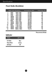
Specifications Preset Modes (Resolution) Display Modes (Resolution) 1 VGA 640 x 350 2 VGA 720 x 400 3 VGA 640 x 480 4 VESA 640 x 480 5 VESA 800 x 600 6 VESA 800 x 600 7 MAC 832 x 624 8 VESA 1024 x 768 9 VESA 1024 x 768 10 MAC 1152 x 870 11 VESA 1152 x 900 *12 VESA 1280 x 1024 13 VESA 1280 x 1024 Horizontal Freq. (kHz) 31.469 31.468 31.469 37.500 37.879 46.875 49.725 48.363 60.023 68.681 61.805 63.981 79.976 Vertical Freq. (Hz) 70 70 60 75 60 75 75 60 75 75 65 60 75 Indicator Mode On Mode Sleep Mode Off Mode LED Color Blue Amber Off *Recommend Mode A15
Specifications Preset Modes (Resolution) Display Modes (Resolution) 1 VGA 640 x 350 2 VGA 720 x 400 3 VGA 640 x 480 4 VESA 640 x 480 5 VESA 800 x 600 6 VESA 800 x 600 7 MAC 832 x 624 8 VESA 1024 x 768 9 VESA 1024 x 768 10 MAC 1152 x 870 11 VESA 1152 x 900 *12 VESA 1280 x 1024 13 VESA 1280 x 1024 Horizontal Freq. (kHz) 31.469 31.468 31.469 37.500 37.879 46.875 49.725 48.363 60.023 68.681 61.805 63.981 79.976 Vertical Freq. (Hz) 70 70 60 75 60 75 75 60 75 75 65 60 75 Indicator Mode On Mode Sleep Mode Off Mode LED Color Blue Amber Off *Recommend Mode A15

User Manual
Page 17
... Ground (return for +5V, H. M. Data018 T. Data0/5 Shield 20 T. D. S. M. S. (Transition Minimized Differential Signaling) A16 Data22 T. Data4+ 6 DDC Clock 7 DDC Data 8 Analog Vertical Sync. 9 T. S. M. M. Clock Shield 23 T. Specifications Signal Connector Pin Assignment 1 8 9 16 17 24 DVI-D Connector Pin Signal(DVI-D) 1 T. M. Data110 T. S. Data0+ 19 T. D. T. Data45 T. D. S. S. M. M. Data5+ 22 T. Clock+ 24 T. M. D. Data2/4 Shield 4 T. M. Data1+ 11 T. S. S. D. D. Data313...
... Ground (return for +5V, H. M. Data018 T. Data0/5 Shield 20 T. D. S. M. S. (Transition Minimized Differential Signaling) A16 Data22 T. Data4+ 6 DDC Clock 7 DDC Data 8 Analog Vertical Sync. 9 T. S. M. M. Clock Shield 23 T. Specifications Signal Connector Pin Assignment 1 8 9 16 17 24 DVI-D Connector Pin Signal(DVI-D) 1 T. M. Data110 T. S. Data0+ 19 T. D. T. Data45 T. D. S. S. M. M. Data5+ 22 T. Clock+ 24 T. M. D. Data2/4 Shield 4 T. M. Data1+ 11 T. S. S. D. D. Data313...

User Manual
Page 18
... a VESA-compliant mounting interface pad.-optional) For further information, refer to Install the VESA Standard wall mounting This monitor meets VESA-compliant mounting interface pad specifications. 1. Kensington Security Slot- Install the VESA standrad wall mounting. optional Connected to another object (stand type and wall-mounted type. Separate the stand base using...
... a VESA-compliant mounting interface pad.-optional) For further information, refer to Install the VESA Standard wall mounting This monitor meets VESA-compliant mounting interface pad specifications. 1. Kensington Security Slot- Install the VESA standrad wall mounting. optional Connected to another object (stand type and wall-mounted type. Separate the stand base using...
User Manual
Page 20
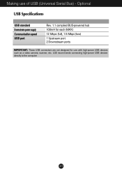
Making use with high-power USB devices such as a video camera, scanner, etc. Optional USB Specifications USB standard Downstream power supply Communication speed USB port Rev. 1.1 complied BUS-powered hub 100mA for each (MAX) 12 Mbps (full), 1.5 Mbps (low) 1 Upstream port 2 Downstream ports IMPORTANT: These USB connectors are not designed for use of USB (Universal Serial Bus) - LGE recommends connecting high-power USB devices directly to the computer A19
Making use with high-power USB devices such as a video camera, scanner, etc. Optional USB Specifications USB standard Downstream power supply Communication speed USB port Rev. 1.1 complied BUS-powered hub 100mA for each (MAX) 12 Mbps (full), 1.5 Mbps (low) 1 Upstream port 2 Downstream ports IMPORTANT: These USB connectors are not designed for use of USB (Universal Serial Bus) - LGE recommends connecting high-power USB devices directly to the computer A19
