Owner's Manual
Page 3
... shall be determined by turning the equipment off and on a circuit different from LG Electronics. Unauthorized modification could void the user's authority to persons. NO USER SERVICEABLE PARTS INSIDE. These limits are designed to Article 820-40 of the device). This...installed and used in particular, specifies that may not cause (harmful) interference, and (2) this equipment does cause harmful interference to Part 15 of important operating and maintenance (servicing) instructions in a particular installation. Operation is connected. - The exclamation point within the...
... shall be determined by turning the equipment off and on a circuit different from LG Electronics. Unauthorized modification could void the user's authority to persons. NO USER SERVICEABLE PARTS INSIDE. These limits are designed to Article 820-40 of the device). This...installed and used in particular, specifies that may not cause (harmful) interference, and (2) this equipment does cause harmful interference to Part 15 of important operating and maintenance (servicing) instructions in a particular installation. Operation is connected. - The exclamation point within the...
Owner's Manual
Page 5
... objects filled with something. 14 CAUTION concerning the Power Cord: It is the disconnecting device. Do not overload wall outlets. a TV with an exact replacement part by connecting it is , a single outlet circuit which powers only that is not disconnected from the AC power source even if you connect the earth...
... objects filled with something. 14 CAUTION concerning the Power Cord: It is the disconnecting device. Do not overload wall outlets. a TV with an exact replacement part by connecting it is , a single outlet circuit which powers only that is not disconnected from the AC power source even if you connect the earth...
Owner's Manual
Page 16
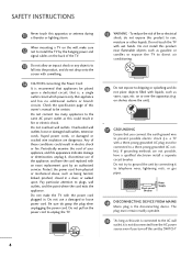
x 3 M5x14 Stand Body Stand Base 3 Assemble the TV as shown. 4 Fix the 4 bolts securely using the holes in the back of the TV. PREPARATION STAND INSTRUCTION I Image shown may differ from damage. 2 Assemble the parts of the Stand Body with the Stand Base of the TV. x 4 M4x28 15 Installation (Except 60PK250, 60PK540, 60PK550, 60PK280, 60PK290, 60PK550C) 1 Carefully place the TV screen side down on a cushioned surface to protect the screen from your TV.
x 3 M5x14 Stand Body Stand Base 3 Assemble the TV as shown. 4 Fix the 4 bolts securely using the holes in the back of the TV. PREPARATION STAND INSTRUCTION I Image shown may differ from damage. 2 Assemble the parts of the Stand Body with the Stand Base of the TV. x 4 M4x28 15 Installation (Except 60PK250, 60PK540, 60PK550, 60PK280, 60PK290, 60PK550C) 1 Carefully place the TV screen side down on a cushioned surface to protect the screen from your TV.
Owner's Manual
Page 20
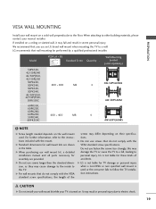
...50PJ350, 42/50PJ250 50PK250, 50PK340, 400 * 400 M6 50PK350, 50PK540, 42/50PJ550, 42/50PJ350C, 50PK550C 60PK550, 60PK250, 60PK280, 60PK290, 50PK540, 60PK550C 600 * 400 M8 4 AW-50PG60MS AW-50PG60M 4 AW-60PG60MS ! NOTE ... of accidents. G When purchasing our wall mount kit, a detailed installation manual and all parts necessary for TV damage or personal injury when a non-VESA or non specified wall mount ... screws too strongly, this may cause damage to the inside to personal injury. LG is used . G LG is turned on. We recommend that do not comply with the mount. G For...
...50PJ350, 42/50PJ250 50PK250, 50PK340, 400 * 400 M6 50PK350, 50PK540, 42/50PJ550, 42/50PJ350C, 50PK550C 60PK550, 60PK250, 60PK280, 60PK290, 50PK540, 60PK550C 600 * 400 M8 4 AW-50PG60MS AW-50PG60M 4 AW-60PG60MS ! NOTE ... of accidents. G When purchasing our wall mount kit, a detailed installation manual and all parts necessary for TV damage or personal injury when a non-VESA or non specified wall mount ... screws too strongly, this may cause damage to the inside to personal injury. LG is used . G LG is turned on. We recommend that do not comply with the mount. G For...
Owner's Manual
Page 71
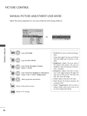
Select Contrast, Brightness, Sharpness, Color, Tint or Color Temperature. You may use Contrast when the bright part of picture is saturated. I Color: Adjusts intensity of crispness in the picture. EXIT Return to the previous menu. I Sharpness: Adjusts the level of all colors.... I Contrast: Increase or decrease the gradient of the picture is saturated. You may use brightness when the dark part of the video signal. I Color Temperature: Set to warm to enhance hotter colors such as red, or set to cool to suit your preference and...
Select Contrast, Brightness, Sharpness, Color, Tint or Color Temperature. You may use Contrast when the bright part of picture is saturated. I Color: Adjusts intensity of crispness in the picture. EXIT Return to the previous menu. I Sharpness: Adjusts the level of all colors.... I Contrast: Increase or decrease the gradient of the picture is saturated. You may use brightness when the dark part of the video signal. I Color Temperature: Set to warm to enhance hotter colors such as red, or set to cool to suit your preference and...
Owner's Manual
Page 74
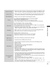
... adjust the overall color of the video signal and can adjust Red, Green or Blue according to the feeling you make adjustments by making bright parts brighter and dark parts darker. Color difference may not be set to use and set it at 24 frames per second.
... adjust the overall color of the video signal and can adjust Red, Green or Blue according to the feeling you make adjustments by making bright parts brighter and dark parts darker. Color difference may not be set to use and set it at 24 frames per second.

Owner's Manual
Page 120
... 05 = 0000 0001 in Hex. * 7th bit : For which must be converted to 0. * 3-0 bits: Choose signal type. 22. Data 05: 7 Main/Sub Picture 6 Two/One Part Channel 5 Using Physical 4 Channel Reserved 3 2 1 0 Step 0 Main 1 Sub 0 Two 1 One 0 Use x 0 0 0 0 NTSC Air 1 No Use x 0 0 0 1 NTSC Cable x 0 0 1 0 ATSC Air x 0 0 1 ...to an NTSC cable channel is "1000 0001", which translates to change the channel. * 6th bit: Use a two part or one part channel. Transmission [m][b][ ][Set ID][ ][Data][Cr] Data 00: Channel Delete Data 01: Channel Add Acknowledgement [b][ ][Set...
... 05 = 0000 0001 in Hex. * 7th bit : For which must be converted to 0. * 3-0 bits: Choose signal type. 22. Data 05: 7 Main/Sub Picture 6 Two/One Part Channel 5 Using Physical 4 Channel Reserved 3 2 1 0 Step 0 Main 1 Sub 0 Two 1 One 0 Use x 0 0 0 0 NTSC Air 1 No Use x 0 0 0 1 NTSC Cable x 0 0 1 0 ATSC Air x 0 0 1 ...to an NTSC cable channel is "1000 0001", which translates to change the channel. * 6th bit: Use a two part or one part channel. Transmission [m][b][ ][Set ID][ ][Data][Cr] Data 00: Channel Delete Data 01: Channel Add Acknowledgement [b][ ][Set...


