Owners Manual
Page 2
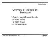
Troubleshooting Overview of Topics to be Discussed •Switch Mode Power Supply •Y SUS Board •Z SUS Board •X Drive Boards Plasma Display Panel Troubleshooting - 2007 2
Troubleshooting Overview of Topics to be Discussed •Switch Mode Power Supply •Y SUS Board •Z SUS Board •X Drive Boards Plasma Display Panel Troubleshooting - 2007 2

Owners Manual
Page 4
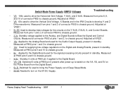
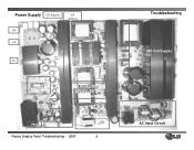
...voltage levels for the DC 5v, VA, VS, V SET UP, -VY, VSC, and Z Bias as they will cover troubleshooting the Switch Mode Power Supply for troubleshooting and alignments. • DC Voltages developed on the SMPS • Adjustments VA, VS, and 5V DC • Always refer to Panel... Switch Mode Power Supply Troubleshooting This Section of the Presentation will vary from Panel to the sticker located in the upper right side of the Power Supply circuit and will be able to locate voltage and test points needed for the Single Scan Plasma. V SET_UP -VY VSC Z_BIAS Plasma Display Panel ...
...voltage levels for the DC 5v, VA, VS, V SET UP, -VY, VSC, and Z Bias as they will cover troubleshooting the Switch Mode Power Supply for troubleshooting and alignments. • DC Voltages developed on the SMPS • Adjustments VA, VS, and 5V DC • Always refer to Panel... Switch Mode Power Supply Troubleshooting This Section of the Presentation will vary from Panel to the sticker located in the upper right side of the Power Supply circuit and will be able to locate voltage and test points needed for the Single Scan Plasma. V SET_UP -VY VSC Z_BIAS Plasma Display Panel ...
Owners Manual
Page 5
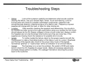
... the failure. Frequency of power supplies will change with the Oscilloscope to those circuits under test. If the supplies are missing check the resistance for possible short circuits. • Isolate To further isolate the failure check for proper levels. Plasma Display Panel Troubleshooting - 2007... 5 Make all necessary adjustments and lastly always perform a Safety AC Leakage Test before returning the product back to check the DC Supplies for the proper waveforms with the load, or...
... the failure. Frequency of power supplies will change with the Oscilloscope to those circuits under test. If the supplies are missing check the resistance for possible short circuits. • Isolate To further isolate the failure check for proper levels. Plasma Display Panel Troubleshooting - 2007... 5 Make all necessary adjustments and lastly always perform a Safety AC Leakage Test before returning the product back to check the DC Supplies for the proper waveforms with the load, or...

Owners Manual
Page 6
...the Digital Board through P800 Pin 6 and used to turn on the VA, and VS Supplies • 5V-M Sent from the Digital Board to the Power Board to turn on connector P800 Pin 5 used to bring the Power Supply out of the Standby Voltages and the VA, VS, and 5v DC, set will output...TVGOS Data. • Standby Operation - Guide Plus has been programmed or a Cable Card is installed and unit is plugged in Standby Mode when turned off . Plasma Display Panel Troubleshooting - 2007 6 Needed to enable the Micro Processor to output the RL-ON Signal to turn on the SMPS. • Digital Board sends...
...the Digital Board through P800 Pin 6 and used to turn on the VA, and VS Supplies • 5V-M Sent from the Digital Board to the Power Board to turn on connector P800 Pin 5 used to bring the Power Supply out of the Standby Voltages and the VA, VS, and 5v DC, set will output...TVGOS Data. • Standby Operation - Guide Plus has been programmed or a Cable Card is installed and unit is plugged in Standby Mode when turned off . Plasma Display Panel Troubleshooting - 2007 6 Needed to enable the Micro Processor to output the RL-ON Signal to turn on the SMPS. • Digital Board sends...
Owners Manual
Page 7
... waveforms. Measured from pins 1 and 2 of connector P805 to chassis ground. • 12v Used for the Audio Output Supply, present in standby. Switch Mode Power Supply (SMPS) Voltages Troubleshooting • VS 196v used to drive the Vertical Grid Voltage, X Boards and in standby. Measured .... Measured from pins 1 and 2 of connector P804 to the Digital Board used for supplying low voltage regulators on the 5V-DC Supply. Measured at P802 pins 1 and 2 to chassis ground. Plasma Display Panel Troubleshooting - 2007 7 Standby voltage applied to the Analog, and Digital Boards...
... waveforms. Measured from pins 1 and 2 of connector P805 to chassis ground. • 12v Used for the Audio Output Supply, present in standby. Switch Mode Power Supply (SMPS) Voltages Troubleshooting • VS 196v used to drive the Vertical Grid Voltage, X Boards and in standby. Measured .... Measured from pins 1 and 2 of connector P804 to the Digital Board used for supplying low voltage regulators on the 5V-DC Supply. Measured at P802 pins 1 and 2 to chassis ground. Plasma Display Panel Troubleshooting - 2007 7 Standby voltage applied to the Analog, and Digital Boards...
Owners Manual
Page 8
Power Supply VS Adjust VA Adjust VS VA Source VA 5v VS Source Control IC 3.3v Adjust 19v Audio Supply 12V,6V, 5V and 3.3V Source Standby Circuit P802 P803 P800 Plasma Display Panel Troubleshooting - 2007 8 Troubleshooting 380 Volt Supply AC Input Circuit
Power Supply VS Adjust VA Adjust VS VA Source VA 5v VS Source Control IC 3.3v Adjust 19v Audio Supply 12V,6V, 5V and 3.3V Source Standby Circuit P802 P803 P800 Plasma Display Panel Troubleshooting - 2007 8 Troubleshooting 380 Volt Supply AC Input Circuit
Owners Manual
Page 9
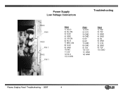
Power Supply Low Voltage Connectors Troubleshooting P800 PIN1 P803 PIN 1 P802 PIN 1 P800 1) AC-D 2) RL-ON 3) S-5V 4) GND 5) VS-ON 6) 5V-D 7) M5V-ON 8) S-5V 9) GND 10) NC 11) 6V 12) N.C 13) 3.3ON P803 1) 3.3V 2) 3.3V 3) GND 4) GND 5) 6V 6) 6V 7) GND 8) GND 9) 12V 10) 12V 11) GND 12) GND P802 1) 19V 2) 19V 3) GND 4) GND 5) 6V 6) GND 7) 3.3V 8) GND 9) 12V 10) GND Plasma Display Panel Troubleshooting - 2007 9
Power Supply Low Voltage Connectors Troubleshooting P800 PIN1 P803 PIN 1 P802 PIN 1 P800 1) AC-D 2) RL-ON 3) S-5V 4) GND 5) VS-ON 6) 5V-D 7) M5V-ON 8) S-5V 9) GND 10) NC 11) 6V 12) N.C 13) 3.3ON P803 1) 3.3V 2) 3.3V 3) GND 4) GND 5) 6V 6) 6V 7) GND 8) GND 9) 12V 10) 12V 11) GND 12) GND P802 1) 19V 2) 19V 3) GND 4) GND 5) 6V 6) GND 7) 3.3V 8) GND 9) 12V 10) GND Plasma Display Panel Troubleshooting - 2007 9
Owners Manual
Page 10
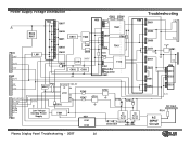
...Q151 Standby Regulator U501 S-5V U601 PCs Control S-5V IC 28 U701 24 20 19 D502 R745 R747 Q702 Q701 D703 D704 Low Voltage Standby Power Supply T501 HS1 D101 D102 AC Relay RL101 AC Relay RL102 120VAC D506 D501 TH01 TH02 Troubleshooting D951 VS D952 D953 D271 6V D261 Q252 D251... D202 VA 5V-M Q281 5V HS6 U261 Q223 D221 3.3v AC Input F101 AC INPUT Circuit Plasma Display Panel Troubleshooting - 2007 10 Power Supply Voltage Distribution HS2 Q607 Q801 PC901 HS3 U801 HS4 T801 R606 R607 Q606 Q601 U851 T902 Q854 R963 P802 19V 3.3V 12V P803...
...Q151 Standby Regulator U501 S-5V U601 PCs Control S-5V IC 28 U701 24 20 19 D502 R745 R747 Q702 Q701 D703 D704 Low Voltage Standby Power Supply T501 HS1 D101 D102 AC Relay RL101 AC Relay RL102 120VAC D506 D501 TH01 TH02 Troubleshooting D951 VS D952 D953 D271 6V D261 Q252 D251... D202 VA 5V-M Q281 5V HS6 U261 Q223 D221 3.3v AC Input F101 AC INPUT Circuit Plasma Display Panel Troubleshooting - 2007 10 Power Supply Voltage Distribution HS2 Q607 Q801 PC901 HS3 U801 HS4 T801 R606 R607 Q606 Q601 U851 T902 Q854 R963 P802 19V 3.3V 12V P803...
Owners Manual
Page 22
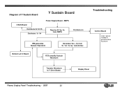
Diagram of Y Sustain Board Y Sustain Board Z SUS Board Distributes 5v VA VS Distributes 5v VA Power Supply Board - Bottom Left X Board FETs amplify Sustain Waveform Troubleshooting Control Board Logic signals needed to generate drive waveform Transfer Waveform to Y Drive Board Display Panel Plasma Display Panel Troubleshooting - 2007 22 SMPS Receive 5V,Va, Vs from SMPS Distributes 5v IPM generates Sustain Waveform Generates Vsc, -Vy from 5v VA Vs by transformer.
Diagram of Y Sustain Board Y Sustain Board Z SUS Board Distributes 5v VA VS Distributes 5v VA Power Supply Board - Bottom Left X Board FETs amplify Sustain Waveform Troubleshooting Control Board Logic signals needed to generate drive waveform Transfer Waveform to Y Drive Board Display Panel Plasma Display Panel Troubleshooting - 2007 22 SMPS Receive 5V,Va, Vs from SMPS Distributes 5v IPM generates Sustain Waveform Generates Vsc, -Vy from 5v VA Vs by transformer.


