Owner's Manual
Page 1
LCD TV MODELS 32LD400 42LD400 47LD500 P/NO :1947-1600-1050 www.lg.com OWNER'S MANUAL LCD TV Please read this manual carefully before operating your set and retain it for future reference.
LCD TV MODELS 32LD400 42LD400 47LD500 P/NO :1947-1600-1050 www.lg.com OWNER'S MANUAL LCD TV Please read this manual carefully before operating your set and retain it for future reference.

Owner's Manual
Page 4
..., make the TV with something. 14 CAUTION concerning the Power Cord: It is recommend that appliances be placed upon . Check the specification page of this owner's manual to fall into the product, and do grasp the plug when unplugging the power cord. Power Supply Short-circuit Breaker 18 DISCONNECTING DEVICE FROM MAINS...
..., make the TV with something. 14 CAUTION concerning the Power Cord: It is recommend that appliances be placed upon . Check the specification page of this owner's manual to fall into the product, and do grasp the plug when unplugging the power cord. Power Supply Short-circuit Breaker 18 DISCONNECTING DEVICE FROM MAINS...
Owner's Manual
Page 8
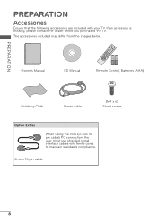
D-sub 15 pin cable 8 The accessories included may differ from the images below. Owner's Manual CD Manual 1.5V 1.5V Remote Control, Batteries (AAA) Polishing Cloth Power cable (M4 x 6) Stand screws Option Extras When using the VGA (D-sub 15 pin cable) PC connection, the user must use shielded signal interface cables with your TV. If an accessory is missing, please contact the dealer where you purchased the TV. PREPARATION PREPARATION Accessories Ensure that the following accessories are included with ferrite cores to maintain standards compliance.
D-sub 15 pin cable 8 The accessories included may differ from the images below. Owner's Manual CD Manual 1.5V 1.5V Remote Control, Batteries (AAA) Polishing Cloth Power cable (M4 x 6) Stand screws Option Extras When using the VGA (D-sub 15 pin cable) PC connection, the user must use shielded signal interface cables with your TV. If an accessory is missing, please contact the dealer where you purchased the TV. PREPARATION PREPARATION Accessories Ensure that the following accessories are included with ferrite cores to maintain standards compliance.

Owner's Manual
Page 17
... connect 1 Connect the video outputs (Y, PB, PR) of the digital set -top box to the COMPONENT IN AUDIO jack on the TV. How to the owner's manual for the digital set -top box. However, if you have finished connecting all equipment. Component Connection 1. EXTERNAL EQUIPMENT SETUP r To prevent the equipment damage, never...
... connect 1 Connect the video outputs (Y, PB, PR) of the digital set -top box to the COMPONENT IN AUDIO jack on the TV. How to the owner's manual for the digital set -top box. However, if you have finished connecting all equipment. Component Connection 1. EXTERNAL EQUIPMENT SETUP r To prevent the equipment damage, never...

Owner's Manual
Page 18
... separate audio connection is necessary. How to connect 1 Connect the digital set-top box to the owner's manual for the digital set -top box. (Refer to HDMI/DVI IN 1, 2, or 3* jack on the remote control. * HDMI 3: For 47LD500 / DVI IN RGB IN RGB (PC) AUDIO 1 AV IN VIDEO AUDIO ANTENNA/ CABLE IN OPTICAL...
... separate audio connection is necessary. How to connect 1 Connect the digital set-top box to the owner's manual for the digital set -top box. (Refer to HDMI/DVI IN 1, 2, or 3* jack on the remote control. * HDMI 3: For 47LD500 / DVI IN RGB IN RGB (PC) AUDIO 1 AV IN VIDEO AUDIO ANTENNA/ CABLE IN OPTICAL...

Owner's Manual
Page 19
DVD Setup Component Connection 1. Y PB PR L R 1 2 2 Connect the audio output of the digital set -top box. (Refer to the DVD player's manual for this connection. DVI to the COMPONENT IN AUDIO jack on the TV. / DVI IN RGB IN RGB (PC) AUDIO 1 AV IN VIDEO AUDIO ANTENNA/ ...) of the digital set-top box to HDMI Connection 1. How to the COMPONENT IN VIDEO jack on the DVD player, insert a DVD. r Refer to the owner's manual for the digital set -top box audio output to HDMI cable or adapter is necessary. Match the jack colors (Y = green, PB = blue, and PR = red...
DVD Setup Component Connection 1. Y PB PR L R 1 2 2 Connect the audio output of the digital set -top box. (Refer to the DVD player's manual for this connection. DVI to the COMPONENT IN AUDIO jack on the TV. / DVI IN RGB IN RGB (PC) AUDIO 1 AV IN VIDEO AUDIO ANTENNA/ ...) of the digital set-top box to HDMI Connection 1. How to the COMPONENT IN VIDEO jack on the DVD player, insert a DVD. r Refer to the owner's manual for the digital set -top box audio output to HDMI cable or adapter is necessary. Match the jack colors (Y = green, PB = blue, and PR = red...

Owner's Manual
Page 21
r Insert a video tape into the VCR and press PLAY on the VCR. (Refer to the VCR owner's manual.) r Select the AV input source on the TV using the INPUT button on the remote control. / DVI IN RGB IN RGB (PC) AUDIO 1 AV IN ... use r Set VCR output switch to 3 or 4 and then tune TV to the RF antenna in socket of the TV. 21 How to the VCR owner's manual). 1 ANTENNA/ CABLE IN ANT OUT S-VIDEO VIDEO L R AUDIO ANT IN OUTPUT SWITCH 2 Wall Jack Antenna Composite (RCA) Connection 1. How to connect 1 Connect the RF antenna...
r Insert a video tape into the VCR and press PLAY on the VCR. (Refer to the VCR owner's manual.) r Select the AV input source on the TV using the INPUT button on the remote control. / DVI IN RGB IN RGB (PC) AUDIO 1 AV IN ... use r Set VCR output switch to 3 or 4 and then tune TV to the RF antenna in socket of the TV. 21 How to the VCR owner's manual). 1 ANTENNA/ CABLE IN ANT OUT S-VIDEO VIDEO L R AUDIO ANT IN OUTPUT SWITCH 2 Wall Jack Antenna Composite (RCA) Connection 1. How to connect 1 Connect the RF antenna...


