Owners Manual
Page 2
... radio/TV technician for help. • Any changes or modifications not expressly approved by turning the equipment off and on a circuit different from LG Electronics. Reorient or relocate the receiving antenna. - COMPLIANCE: The responsible party for compliance could void the user's warranty. The lightning flash with the limits for a Class B digital device, pursuant to Part 15 of electric...
... radio/TV technician for help. • Any changes or modifications not expressly approved by turning the equipment off and on a circuit different from LG Electronics. Reorient or relocate the receiving antenna. - COMPLIANCE: The responsible party for compliance could void the user's warranty. The lightning flash with the limits for a Class B digital device, pursuant to Part 15 of electric...

Owners Manual
Page 5
Owner's Manual 5 Contents Contents Safety Instructions 2~4 Introduction Accessories 7 Controls and Connection Options 8~9 Remote Control Key Functions 10 Installation Installation Instructions 11 External Equipment Connections 12~16 When Connecting to original factory settings) . . .31 External Control Device Setup 32~37 IR Code 38~39 Troubleshooting Checklist 40 Product Specifications 41 After reading this manual, keep it handy for future reference. Black level 20 Reset 20 Sound Menu Options SSM 21 AVL (Auto Volume Leveler 21 Balance 22 Speaker 22 Timer...
Owner's Manual 5 Contents Contents Safety Instructions 2~4 Introduction Accessories 7 Controls and Connection Options 8~9 Remote Control Key Functions 10 Installation Installation Instructions 11 External Equipment Connections 12~16 When Connecting to original factory settings) . . .31 External Control Device Setup 32~37 IR Code 38~39 Troubleshooting Checklist 40 Product Specifications 41 After reading this manual, keep it handy for future reference. Black level 20 Reset 20 Sound Menu Options SSM 21 AVL (Auto Volume Leveler 21 Balance 22 Speaker 22 Timer...
Owners Manual
Page 8
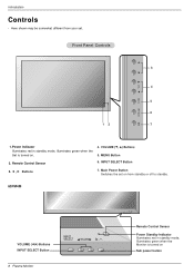
Power Indicator Illuminates red in standby mode, Illuminates green when the Monitor is turned on Sub power button Front Panel Controls 3 4 5 6 12 7 1. Main Power Button Switches the set . MENU Button 2. INPUT SELECT Button 3. Remote Control Sensor 6. Here shown may be somewhat different from your set on from standby or off to standby. 60PM4M VOLUME (F,G) Buttons INPUT SELECT Button INPUT SELECT VOLUME 8 Plasma Monitor INPUT SELECT VOLUME Remote Control Sensor Power Standby Indicator Illuminates red in standby mode, Illuminates green when the Set is turned on...
Power Indicator Illuminates red in standby mode, Illuminates green when the Monitor is turned on Sub power button Front Panel Controls 3 4 5 6 12 7 1. Main Power Button Switches the set . MENU Button 2. INPUT SELECT Button 3. Remote Control Sensor 6. Here shown may be somewhat different from your set on from standby or off to standby. 60PM4M VOLUME (F,G) Buttons INPUT SELECT Button INPUT SELECT VOLUME 8 Plasma Monitor INPUT SELECT VOLUME Remote Control Sensor Power Standby Indicator Illuminates red in standby mode, Illuminates green when the Set is turned on...
Owners Manual
Page 9
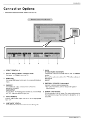
REMOTE CONTROL IN 2. Or connect a DVI(Video) signal. 4. RGB INPUT Connect the set , connect RGB OUTPUT to 'Speaker & Speaker Stand' manual. 9. RGB OUTPUT You can watch the RGB signal on another set operates on the Specifications page. EXTERNAL SPEAKER (8 ohm output) Connect to optional external speaker(s). * For further information, refer to another set output connector from a PC to the appropriate input port. Owner's Manual 9 RS-232C INPUT(CONTROL&SERVICE) PORT Connect to these jacks. AV OUT 8. The voltage is indicated on an AC power. POWER CORD SOCKET This set 's PC...
REMOTE CONTROL IN 2. Or connect a DVI(Video) signal. 4. RGB INPUT Connect the set , connect RGB OUTPUT to 'Speaker & Speaker Stand' manual. 9. RGB OUTPUT You can watch the RGB signal on another set operates on the Specifications page. EXTERNAL SPEAKER (8 ohm output) Connect to optional external speaker(s). * For further information, refer to another set output connector from a PC to the appropriate input port. Owner's Manual 9 RS-232C INPUT(CONTROL&SERVICE) PORT Connect to these jacks. AV OUT 8. The voltage is indicated on an AC power. POWER CORD SOCKET This set 's PC...
Owners Manual
Page 10
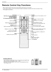
.... POWER AV INPUT SLEEP PSM ARC AUTO 1 2 3 4 5 6 7 8 9 0 MENU EXIT SET MUTE * POWER switches the set on the monitor. - SET accepts your selection or displays the current mode. SLEEP Sets the sleep timer. AUTO Automatic adjustment function. (Operational for the analog signal only) ARC Changes the picture format. Replace cover. 10 Plasma Monitor Introduction Remote Control Key Functions - NUMBER buttons There is not a function which is supported. Selects menu item. * : No function Installing Batteries • Open the battery compartment cover on screen...
.... POWER AV INPUT SLEEP PSM ARC AUTO 1 2 3 4 5 6 7 8 9 0 MENU EXIT SET MUTE * POWER switches the set on the monitor. - SET accepts your selection or displays the current mode. SLEEP Sets the sleep timer. AUTO Automatic adjustment function. (Operational for the analog signal only) ARC Changes the picture format. Replace cover. 10 Plasma Monitor Introduction Remote Control Key Functions - NUMBER buttons There is not a function which is supported. Selects menu item. * : No function Installing Batteries • Open the battery compartment cover on screen...
Owners Manual
Page 11
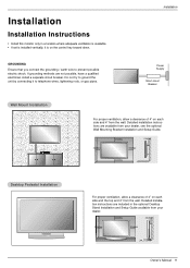
... and 4" from your dealer. 4 inches 4 inches 4 inches 4 inches Owner's Manual 11 GROUNDING Ensure that you connect the grounding / earth wire to telephone wires, lightening rods, or gas pipes. Installation Power Supply Short-circuit Breaker Wall Mount Installation For proper ventilation, allow a clearance of 4" on the control key toward down. Installation Installation Instructions • Install this monitor only in the optional Desktop Stand Installation and Setup Guide available from the wall. If grounding methods are...
... and 4" from your dealer. 4 inches 4 inches 4 inches 4 inches Owner's Manual 11 GROUNDING Ensure that you connect the grounding / earth wire to telephone wires, lightening rods, or gas pipes. Installation Power Supply Short-circuit Breaker Wall Mount Installation For proper ventilation, allow a clearance of 4" on the control key toward down. Installation Installation Instructions • Install this monitor only in the optional Desktop Stand Installation and Setup Guide available from the wall. If grounding methods are...
Owners Manual
Page 12
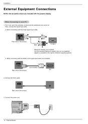
... Plasma Monitor When Connecting to DVI signal input cable (not included). When connecting with the HDMI to your PC 1. Connect the Audio cable. PC 3. Then, connect the signal input cable. a. HDMI/DVI IN (not included) Rear side of the product. Installation External Equipment Connections NOTE: Not all , see if the computer, product and the peripherals are included with the D-Sub signal input cable. When connecting with the plasma display. PC MAC PC/MAC Macintosh Adapter (not included) Use...
... Plasma Monitor When Connecting to DVI signal input cable (not included). When connecting with the HDMI to your PC 1. Connect the Audio cable. PC 3. Then, connect the signal input cable. a. HDMI/DVI IN (not included) Rear side of the product. Installation External Equipment Connections NOTE: Not all , see if the computer, product and the peripherals are included with the D-Sub signal input cable. When connecting with the plasma display. PC MAC PC/MAC Macintosh Adapter (not included) Use...
Owners Manual
Page 13
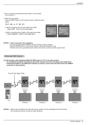
Installation 4. Turn on power by pressing the power button on the PC. 5. We recommend that you should use different products connected to select the input signal. Owner's Manual 13 Select an input signal. INPUT D /E SET a. When connecting with a ground wire. Input AV Component1 Component2 RGB HDMI/DVI Input AV Component1 Component2 RGB HDMI/DVI NOTES: • How to connect to DVI Digital signal. Press the INPUT button on the remote control to select the computer to use. • Directly connect to a grounded power outlet on the...
Installation 4. Turn on power by pressing the power button on the PC. 5. We recommend that you should use different products connected to select the input signal. Owner's Manual 13 Select an input signal. INPUT D /E SET a. When connecting with a ground wire. Input AV Component1 Component2 RGB HDMI/DVI Input AV Component1 Component2 RGB HDMI/DVI NOTES: • How to connect to DVI Digital signal. Press the INPUT button on the remote control to select the computer to use. • Directly connect to a grounded power outlet on the...
Owners Manual
Page 14
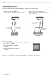
... AV IN VIDEO L-AUDIO-R S-VIDEO AV OUT b. When connecting with S-Video cable, S-Video cable is connected simultaneously with an BNC cable. • Select AV. Input AV Component1 Component2 RGB HDMI/DVI NOTES: • When the BNC cable is first. 14 Plasma Monitor Select an input signal. Press the INPUT button on the remote control to watch high image quality movies. When connecting with a S-Video cable. • Connect to the S-Video input terminal to select the input signal. a. Connect the video cable as shown in...
... AV IN VIDEO L-AUDIO-R S-VIDEO AV OUT b. When connecting with S-Video cable, S-Video cable is connected simultaneously with an BNC cable. • Select AV. Input AV Component1 Component2 RGB HDMI/DVI NOTES: • When the BNC cable is first. 14 Plasma Monitor Select an input signal. Press the INPUT button on the remote control to watch high image quality movies. When connecting with a S-Video cable. • Connect to the S-Video input terminal to select the input signal. a. Connect the video cable as shown in...
Owners Manual
Page 15
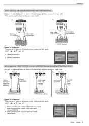
... HDMI/DVI/RGB from the VCR/DVD/Set-top Box (480p/576p/720p/1080i) 1. INPUT D /E SET a. a. Press the INPUT button on the remote control to select the input signal. Product COMPONENT IN VIDEO L-AUDIO-R 1 2 b. a. When connecting with a D-Sub signal input cable. • Select RGB VCR/DVD/Set-top Box Input AV Component1 Component2 RGB HDMI/DVI Input AV Component1 Component2 RGB HDMI/DVI Owner's Manual 15 Connect the video/audio cable as shown in the below figure and then connect the power cord. Select an input signal. Connect the video/audio cable...
... HDMI/DVI/RGB from the VCR/DVD/Set-top Box (480p/576p/720p/1080i) 1. INPUT D /E SET a. a. Press the INPUT button on the remote control to select the input signal. Product COMPONENT IN VIDEO L-AUDIO-R 1 2 b. a. When connecting with a D-Sub signal input cable. • Select RGB VCR/DVD/Set-top Box Input AV Component1 Component2 RGB HDMI/DVI Input AV Component1 Component2 RGB HDMI/DVI Owner's Manual 15 Connect the video/audio cable as shown in the below figure and then connect the power cord. Select an input signal. Connect the video/audio cable...
Owners Manual
Page 16
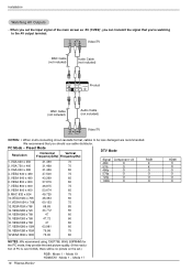
... picture on the set the input signal of PC is over UXGA, there will be less damaged are recommended. VESA 800 x 600 46.875 75 8. VESA1360 x 768 47.72 60 16. VESA1280 x 1024 63.981 60 18. Installation Watching AV Outputs • When you set .) RGB : Mode 1 ~ Mode 19 HDMI/DVI : Mode 1 ~ Mode 17 16 Plasma Monitor HDMI X X O O O O Video/TV BNC Cable (not included) Audio Cable (not included) AV IN VIDEO L-AUDIO-R S-VIDEO...
... picture on the set the input signal of PC is over UXGA, there will be less damaged are recommended. VESA 800 x 600 46.875 75 8. VESA1360 x 768 47.72 60 16. VESA1280 x 1024 63.981 60 18. Installation Watching AV Outputs • When you set .) RGB : Mode 1 ~ Mode 19 HDMI/DVI : Mode 1 ~ Mode 17 16 Plasma Monitor HDMI X X O O O O Video/TV BNC Cable (not included) Audio Cable (not included) AV IN VIDEO L-AUDIO-R S-VIDEO...

Owners Manual
Page 18
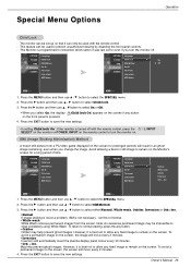
...button and then use D / E button to make appropriate adjustments. 6. To initialize values (reset to the best picture appearance. - When adjusting picture options (contrast, brightness, colour, sharpness and tint (NTSC input only)) manually, PSM is automatically changed . Menu Prev. 1. Press the G button and then use F / G button to select CSM. 3. PSM (Picture Status Memory) - Manual Picture Control (user option) - Press the MENU button and then use D / E button to select the PICTURE menu. 2. Operation Picture Menu Options - Press the G button and then use D / E button...
...button and then use D / E button to make appropriate adjustments. 6. To initialize values (reset to the best picture appearance. - When adjusting picture options (contrast, brightness, colour, sharpness and tint (NTSC input only)) manually, PSM is automatically changed . Menu Prev. 1. Press the G button and then use F / G button to select CSM. 3. PSM (Picture Status Memory) - Manual Picture Control (user option) - Press the MENU button and then use D / E button to select the PICTURE menu. 2. Operation Picture Menu Options - Press the G button and then use D / E button...
Owners Manual
Page 19
... User. 4. Press the G button and then use this function in PC[RGB/HDMI] mode. Press the MENU button and then use D / E button to display a real HD source through an advanced digital signal processing algorithm. - Press the EXIT button to save the new settings. * Selecting the Manual This menu is activated after selecting the User1 or User2 of Red, Green and Blue is LG electronic's unique picture improving technology to select Red, Green or Blue. 5. You can adjust red, green, or blue...
... User. 4. Press the G button and then use this function in PC[RGB/HDMI] mode. Press the MENU button and then use D / E button to display a real HD source through an advanced digital signal processing algorithm. - Press the EXIT button to save the new settings. * Selecting the Manual This menu is activated after selecting the User1 or User2 of Red, Green and Blue is LG electronic's unique picture improving technology to select Red, Green or Blue. 5. You can adjust red, green, or blue...
Owners Manual
Page 25
... White Wash removes permanent images from a PC/video game displayed on the screen. Menu Prev. 1. Menu Prev. 1. set up so that it is pressed. 4. To avoid a permanent image on . / I, INPUT ISM (Image Sticking Minimization) Method - Special Menu Options Operation Child Lock - A frozen still picture from the screen. Note: An excessive permanent image may help prevent ghost images. May help prevent ghost images. Press the EXIT button to clear completely using White Wash. Owner's Manual 25 This Monitor...
... White Wash removes permanent images from a PC/video game displayed on the screen. Menu Prev. 1. Menu Prev. 1. set up so that it is pressed. 4. To avoid a permanent image on . / I, INPUT ISM (Image Sticking Minimization) Method - Special Menu Options Operation Child Lock - A frozen still picture from the screen. Note: An excessive permanent image may help prevent ghost images. May help prevent ghost images. Press the EXIT button to clear completely using White Wash. Owner's Manual 25 This Monitor...
Owners Manual
Page 30
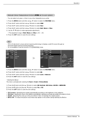
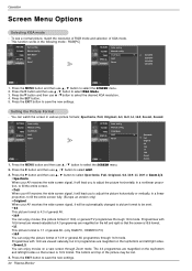
... Manual config. Press the G button and then use D / E button to select XGA Mode. 3. Press the G button and then use D / E button to select the desired XGA resolution. 4. Manual config. XGA Mode ARC Reset Menu Prev. XGA Mode ARC Reset Menu Prev. Press the G button and then use D / E button to select Spectacle, Full, Original, 4:3, 16:9, 1:1, 14:9 or Zoom 1/2. • Spectacle When your AV receives the wide screen signal, it will lead you to adjust the picture horizontally...
... Manual config. Press the G button and then use D / E button to select XGA Mode. 3. Press the G button and then use D / E button to select the desired XGA resolution. 4. Manual config. XGA Mode ARC Reset Menu Prev. XGA Mode ARC Reset Menu Prev. Press the G button and then use D / E button to select Spectacle, Full, Original, 4:3, 16:9, 1:1, 14:9 or Zoom 1/2. • Spectacle When your AV receives the wide screen signal, it will lead you to adjust the picture horizontally...
Owners Manual
Page 32
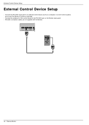
External Control Device Setup External Control Device Setup - Connect the RS-232C input jack to the RS-232C jack on the Monitor back panel. - Connect the serial port of the control device to an external control device (such as a computer or an A/V control system) and control the Monitor's functions externally. - RS-232C connection cables are not supplied with the Monitor. REMOTE CONTROL IN RS-232C (CONTROL&SERVICE) OUT IN HDMI/DVI IN RGB OUT IN AUDIO (RGB/DVI) COMPONENT IN VIDEO L-AUDIO-R 1 2 VIDEO AV...
External Control Device Setup External Control Device Setup - Connect the RS-232C input jack to the RS-232C jack on the Monitor back panel. - Connect the serial port of the control device to an external control device (such as a computer or an A/V control system) and control the Monitor's functions externally. - RS-232C connection cables are not supplied with the Monitor. REMOTE CONTROL IN RS-232C (CONTROL&SERVICE) OUT IN HDMI/DVI IN RGB OUT IN AUDIO (RGB/DVI) COMPONENT IN VIDEO L-AUDIO-R 1 2 VIDEO AV...

Owners Manual
Page 33
... MENU button and then use the D / E button to specify a monitor ID number. - Volume Control k 07. OSD Select k 13. Key m 20. Tile V Size d 23. When selecting Set ID '0', every connected Plasma Monitor set ID to choose desired moni- If the data is error, it returns the data of the PC computer. Menu Prev. 1. Command Reference List COMMAND 1 COMMAND 2 DATA (Hexadecimal) 01. Power k 02. Volume Mute k 06. Brightness k 09. Sharpness k 12. Error...
... MENU button and then use the D / E button to specify a monitor ID number. - Volume Control k 07. OSD Select k 13. Key m 20. Tile V Size d 23. When selecting Set ID '0', every connected Plasma Monitor set ID to choose desired moni- If the data is error, it returns the data of the PC computer. Menu Prev. 1. Command Reference List COMMAND 1 COMMAND 2 DATA (Hexadecimal) 01. Power k 02. Volume Mute k 06. Brightness k 09. Sharpness k 12. Error...
Owners Manual
Page 34
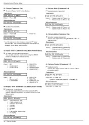
... 6 : RGB (DTV) 7 : RGB (PC) 8 : HDMI/DVI(DTV) 9 : HDMI/DVI(PC) 03. Aspect Ratio (Command 2:c) (Main picture format) G To adjust the screen format. You can also select an input source using the INPUT button on the Monitor's remote control. Transmission [k][d][ ][Set ID][ ][Data][Cr] Data 0 : Screen mute off (Picture on) 1 : Screen mute on (Picture off) Acknowledgement [d][ ][Set ID][ ][OK][Data][x] Data 0 : Screen mute off (Picture on) 1 : Screen mute on remote control or in the Screen menu. See page 35. Power (Command 2:a) G To control Power...
... 6 : RGB (DTV) 7 : RGB (PC) 8 : HDMI/DVI(DTV) 9 : HDMI/DVI(PC) 03. Aspect Ratio (Command 2:c) (Main picture format) G To adjust the screen format. You can also select an input source using the INPUT button on the Monitor's remote control. Transmission [k][d][ ][Set ID][ ][Data][Cr] Data 0 : Screen mute off (Picture on) 1 : Screen mute on (Picture off) Acknowledgement [d][ ][Set ID][ ][OK][Data][x] Data 0 : Screen mute off (Picture on) 1 : Screen mute on remote control or in the Screen menu. See page 35. Power (Command 2:a) G To control Power...

Owners Manual
Page 36
... (Power on and signal exist) 1: No signal (Power on) 2 : Turn the monitor off by remote control 3 : Turn the monitor off by sleep time function 4 : Turn the monitor off by RS-232C function 6 : AC down 8 : Turn the monitor off by off time function 9 : Turn the monitor off by auto off status when Stand-by mode. Auto Configure only works in the Picture menu. Transmission [j][p][ ][Set ID][ ][Data][Cr] Data 1 : Inversion 2 : Orbiter 3 : Orb.+Inv. 4 : White Wash 8 : Normal Acknowledgement [p][ ][Set...
... (Power on and signal exist) 1: No signal (Power on) 2 : Turn the monitor off by remote control 3 : Turn the monitor off by sleep time function 4 : Turn the monitor off by RS-232C function 6 : AC down 8 : Turn the monitor off by off time function 9 : Turn the monitor off by auto off status when Stand-by mode. Auto Configure only works in the Picture menu. Transmission [j][p][ ][Set ID][ ][Data][Cr] Data 1 : Inversion 2 : Orbiter 3 : Orb.+Inv. 4 : White Wash 8 : Normal Acknowledgement [p][ ][Set...
Owners Manual
Page 40
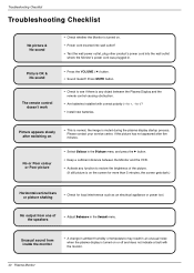
... picture & No sound • Check whether the Monitor is muted during the plasma display startup process. Picture appears slowly after five minutes. Please contact your service center, if the picture has not appeared after switching on • This is normal, the image is turned on. • Power cord inserted into wall outlet? • Test the wall power outlet, plug other product's power cord into the wall outlet where the Monitor's power cord was plugged...
... picture & No sound • Check whether the Monitor is muted during the plasma display startup process. Picture appears slowly after five minutes. Please contact your service center, if the picture has not appeared after switching on • This is normal, the image is turned on. • Power cord inserted into wall outlet? • Test the wall power outlet, plug other product's power cord into the wall outlet where the Monitor's power cord was plugged...


