Owners Manual
Page 2
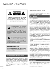
.... This equipment generates, uses and can be determined by one or more of the following two conditions: (1) This device may be connected to the grounding system of the National Electric Code (U.S.A.). This device complies with the limits for help. The exclamation point within the product... This equipment has been tested and found to comply with part 15 of the device). However, there is connected. - Connect the equipment to an outlet on a circuit different from LG Electronics. WARNING/CAUTION TO REDUCE THE RISK OF FIRE AND ELECTRIC SHOCK, DO NOT EXPOSE THIS PRODUCT TO...
.... This equipment generates, uses and can be determined by one or more of the following two conditions: (1) This device may be connected to the grounding system of the National Electric Code (U.S.A.). This device complies with the limits for help. The exclamation point within the product... This equipment has been tested and found to comply with part 15 of the device). However, there is connected. - Connect the equipment to an outlet on a circuit different from LG Electronics. WARNING/CAUTION TO REDUCE THE RISK OF FIRE AND ELECTRIC SHOCK, DO NOT EXPOSE THIS PRODUCT TO...
Owners Manual
Page 4
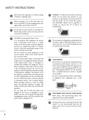
...do not expose this apparatus or antenna during a thunder or lighting storm. Do not install this owner's manual to be certain. that appliances be connected to a three-prong grounded AC outlet). Overloaded wall outlets, loose or damaged wall outlets, extension cords, frayed power cords, or damaged or ... fire or electrical shock, do grasp the plug when unplugging the power cord. Do not make sure 12 not to install the TV by connecting it , discontinue use a damaged or loose power cord. SAFETY INSTRUCTIONS 11 Never touch this product to rain, moisture or other liquids. Do...
...do not expose this apparatus or antenna during a thunder or lighting storm. Do not install this owner's manual to be certain. that appliances be connected to a three-prong grounded AC outlet). Overloaded wall outlets, loose or damaged wall outlets, extension cords, frayed power cords, or damaged or ... fire or electrical shock, do grasp the plug when unplugging the power cord. Do not make sure 12 not to install the TV by connecting it , discontinue use a damaged or loose power cord. SAFETY INSTRUCTIONS 11 Never touch this product to rain, moisture or other liquids. Do...
Owners Manual
Page 5
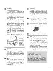
...dusty places. 24 If you smell smoke or other materials (e.g.) plastic while plugged in the U.S.A. ON DISPOSAL (Only Hg lamp used LCD TV) The fluorescent lamp used in Wire Electric Service Equipment NEC: National Electrical Code Antenna Discharge Unit (NEC Section 810-20) Grounding ... to grounding electrodes and requirements for long periods of antenna discharge unit, connection to the regulations of this product must be a small "flicker" when it is proper ventilation. Avoid touching the LCD screen or holding your TV where there is turned on the monitor's performance...
...dusty places. 24 If you smell smoke or other materials (e.g.) plastic while plugged in the U.S.A. ON DISPOSAL (Only Hg lamp used LCD TV) The fluorescent lamp used in Wire Electric Service Equipment NEC: National Electrical Code Antenna Discharge Unit (NEC Section 810-20) Grounding ... to grounding electrodes and requirements for long periods of antenna discharge unit, connection to the regulations of this product must be a small "flicker" when it is proper ventilation. Avoid touching the LCD screen or holding your TV where there is turned on the monitor's performance...
Owners Manual
Page 6
... the TV to a Desk 17 Securing the TV to the wall to prevent falling when the TV is used on a stand 18 Antenna or Cable Connection 19 EXTERNAL EQUIPMENT SETUP HD Receiver Setup 20 DVD Setup 23 VCR Setup 25 Other A/V Source Setup 27 USB... Connection 28 Audio out Connection 29 PC Setup 30 WATCHING TV / CHANNEL CONTROL Remote Control Functions 36 Turning On TV 38 Channel Selection 38 Volume Adjustment 38 Initial Setting 39 ...
... the TV to a Desk 17 Securing the TV to the wall to prevent falling when the TV is used on a stand 18 Antenna or Cable Connection 19 EXTERNAL EQUIPMENT SETUP HD Receiver Setup 20 DVD Setup 23 VCR Setup 25 Other A/V Source Setup 27 USB... Connection 28 Audio out Connection 29 PC Setup 30 WATCHING TV / CHANNEL CONTROL Remote Control Functions 36 Turning On TV 38 Channel Selection 38 Volume Adjustment 38 Initial Setting 39 ...
Owners Manual
Page 9
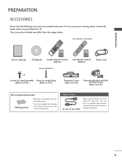
... * Wipe spots on the exterior only with ferrite cores to maintain standards compliance. 9 Option Extras D-sub 15 pin Cable When using the VGA (D-sub 15 pin cable) PC connection, the user must use shielded signal interface cables with the polishing cloth. * Do not wipe roughly when removing stain. The accessories included may...
... * Wipe spots on the exterior only with ferrite cores to maintain standards compliance. 9 Option Extras D-sub 15 pin Cable When using the VGA (D-sub 15 pin cable) PC connection, the user must use shielded signal interface cables with the polishing cloth. * Do not wipe roughly when removing stain. The accessories included may...
Owners Manual
Page 11
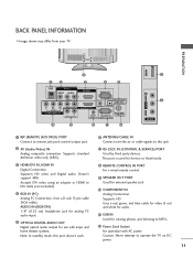
...work. 8 REMOTE CONTROL IN PORT For a wired remote control. 9 SPEAKER OUT PORT Used for external speaker jack. 10 COMPONENT IN Analog Connection. Uses a D-sub 15 pin cable (VGA cable). Uses a red, green, and blue cable for video & red and white for audio. 11 USB IN Used for Service or Hotel... mode. 3 HDMI/DVI IN, HDMI IN Digital Connection. Supports standard definition video only (480i). 7 RS-232C IN (CONTROL & SERVICE) PORT Used by third party ...
...work. 8 REMOTE CONTROL IN PORT For a wired remote control. 9 SPEAKER OUT PORT Used for external speaker jack. 10 COMPONENT IN Analog Connection. Uses a D-sub 15 pin cable (VGA cable). Uses a red, green, and blue cable for video & red and white for audio. 11 USB IN Used for Service or Hotel... mode. 3 HDMI/DVI IN, HDMI IN Digital Connection. Supports standard definition video only (480i). 7 RS-232C IN (CONTROL & SERVICE) PORT Used by third party ...
Owners Manual
Page 15
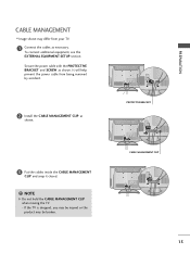
NOTE G Do not hold the CABLE MANAGEMENT CLIP when moving the TV. - PROTECTIVE BRACKET CABLE MANAGEMENT CLIP 15 PREPARATION To connect additional equipment, see the EXTERNAL EQUIPMENT SETUP section. CABLE MANAGEMENT I Image shown may be broken. Secure the power cable with the PROTECTIVE BRACKET and SCREW ... CLIP as shown. 3 Put the cables inside the CABLE MANAGEMENT CLIP and snap it closed. ! It will help prevent the power cable from your TV. 1 Connect the cables as shown.
NOTE G Do not hold the CABLE MANAGEMENT CLIP when moving the TV. - PROTECTIVE BRACKET CABLE MANAGEMENT CLIP 15 PREPARATION To connect additional equipment, see the EXTERNAL EQUIPMENT SETUP section. CABLE MANAGEMENT I Image shown may be broken. Secure the power cable with the PROTECTIVE BRACKET and SCREW ... CLIP as shown. 3 Put the cables inside the CABLE MANAGEMENT CLIP and snap it closed. ! It will help prevent the power cable from your TV. 1 Connect the cables as shown.

Owners Manual
Page 16
G Do not mount near or above any type of the Kensington company. Connect the Kensington Security System cable as notebook PCs and LCD projectors. Kensington sells security systems for all four sides from your viewing position. For the detailed installation and use of 4 inches on the back panel. ...
G Do not mount near or above any type of the Kensington company. Connect the Kensington Security System cable as notebook PCs and LCD projectors. Kensington sells security systems for all four sides from your viewing position. For the detailed installation and use of 4 inches on the back panel. ...
Owners Manual
Page 19
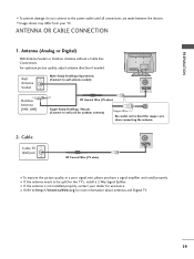
...antenna needs to be split for more information about antennas and Digital TV. 19 PREPARATION I To prevent damage do not connect to bend the copper wire when connecting the antenna. 2. I Image shown may differ from your dealer for outdoor antenna) Copper Wire Be careful not to the...org for two TV's, install a 2-Way Signal Splitter. Antenna (Analog or Digital) Wall Antenna Socket or Outdoor Antenna without a Cable Box Connections. For optimum picture quality, adjust antenna direction if needed. I Refer to wall jack for assistance. I To improve the picture quality in a...
...antenna needs to be split for more information about antennas and Digital TV. 19 PREPARATION I To prevent damage do not connect to bend the copper wire when connecting the antenna. 2. I Image shown may differ from your dealer for outdoor antenna) Copper Wire Be careful not to the...org for two TV's, install a 2-Way Signal Splitter. Antenna (Analog or Digital) Wall Antenna Socket or Outdoor Antenna without a Cable Box Connections. For optimum picture quality, adjust antenna direction if needed. I Refer to wall jack for assistance. I To improve the picture quality in a...
Owners Manual
Page 20
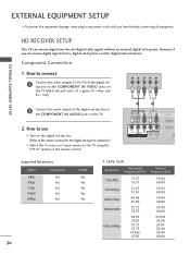
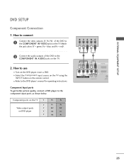
... AUDIO 2 L(MONO) R 1 VIDEO COMPONENT IN L AUDIO R L R SPEAKER OUT /DVI IN REMO CONTRO Supported Resolutions Signal Component 480i Yes 480p Yes 720p Yes 1080i Yes 1080p Yes HDMI No Yes Yes Yes Yes 20 Y, CB/PB, CR/PR Resolution Horizontal Vertical Frequency(KHz) Frequency(Hz) 720x480i 720x480p 1280x720p 1920x1080i 1920x1080p 15.73 15... 59.94 60.00 59.94 60.00 23.976 24.00 29.97 30.00 59.94 60.00 However, if you have finished connecting all equipment. How to use I Turn on the digital set -top box. Match the jack colors (Y = green, PB = blue, and PR = red...
... AUDIO 2 L(MONO) R 1 VIDEO COMPONENT IN L AUDIO R L R SPEAKER OUT /DVI IN REMO CONTRO Supported Resolutions Signal Component 480i Yes 480p Yes 720p Yes 1080i Yes 1080p Yes HDMI No Yes Yes Yes Yes 20 Y, CB/PB, CR/PR Resolution Horizontal Vertical Frequency(KHz) Frequency(Hz) 720x480i 720x480p 1280x720p 1920x1080i 1920x1080p 15.73 15... 59.94 60.00 59.94 60.00 23.976 24.00 29.97 30.00 59.94 60.00 However, if you have finished connecting all equipment. How to use I Turn on the digital set -top box. Match the jack colors (Y = green, PB = blue, and PR = red...
Owners Manual
Page 21
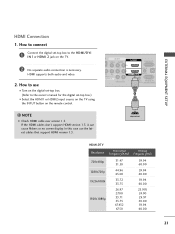
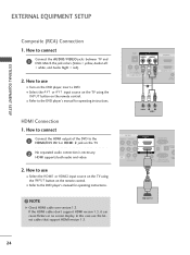
... I Select the HDMI1 or HDMI2 input source on the TV using the INPUT button on the TV. 2 No separate audio connection is necessary. If the HDMI cables don't support HDMI version 1.3, it can cause flickers or no screen display. In this case use I Turn on the digital set-top box. (Refer ...to the owner's manual for the digital set -top box to connect 1 Connect the digital set -top box.) I N 1or HDMI 2 jack on the remote control. ! EXTERNAL EQUIPMENT SETUP HDMI Connection 1. How to use the latest cables that support...
... I Select the HDMI1 or HDMI2 input source on the TV using the INPUT button on the TV. 2 No separate audio connection is necessary. If the HDMI cables don't support HDMI version 1.3, it can cause flickers or no screen display. In this case use I Turn on the digital set-top box. (Refer ...to the owner's manual for the digital set -top box to connect 1 Connect the digital set -top box.) I N 1or HDMI 2 jack on the remote control. ! EXTERNAL EQUIPMENT SETUP HDMI Connection 1. How to use the latest cables that support...
Owners Manual
Page 22
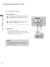
...CONTROL IN (CONTROL&SERVICE) 1 2 ! DVI doesn't support audio, so a separate audio connection is required for the digital set -top box audio output to the HDMI/DVI IN 1or HDMI 2 jack on the TV. 2 Connect the digital set -top box.) I Select the HDMI1 or HDMI2 input source on the ... 2. EXTERNAL EQUIPMENT SETUP EXTERNAL EQUIPMENT SETUP DVI to HDMI cable or adapter is necessary. NOTE G A DVI to HDMI Connection 1. How to use I Turn on the digital set-top box. (Refer to the owner's manual for this connection. How to connect 1 Connect the DVI output of the digital set-top box to...
...CONTROL IN (CONTROL&SERVICE) 1 2 ! DVI doesn't support audio, so a separate audio connection is required for the digital set -top box audio output to the HDMI/DVI IN 1or HDMI 2 jack on the TV. 2 Connect the digital set -top box.) I Select the HDMI1 or HDMI2 input source on the ... 2. EXTERNAL EQUIPMENT SETUP EXTERNAL EQUIPMENT SETUP DVI to HDMI cable or adapter is necessary. NOTE G A DVI to HDMI Connection 1. How to use I Turn on the digital set-top box. (Refer to the owner's manual for this connection. How to connect 1 Connect the DVI output of the digital set-top box to...
Owners Manual
Page 23
... use I Refer to the COMPONENT IN AUDIO jacks on the TV. 2. I Turn on the TV. Component Input ports To get better picture quality, connect a DVD player to the COMPONENT IN VIDEO jacks on the DVD player, insert a DVD. Component ports on the TV Y Y Video output ports Y... PR) of the DVD to the DVD player's manual for operating instructions. EXTERNAL EQUIPMENT SETUP DVD SETUP Component Connection 1. Match the jack colors (Y = green, PB = blue, and PR = red). 2 Connect the audio outputs of the DVD to the component input ports as shown below. I Select the Component input ...
... use I Refer to the COMPONENT IN AUDIO jacks on the TV. 2. I Turn on the TV. Component Input ports To get better picture quality, connect a DVD player to the COMPONENT IN VIDEO jacks on the DVD player, insert a DVD. Component ports on the TV Y Y Video output ports Y... PR) of the DVD to the DVD player's manual for operating instructions. EXTERNAL EQUIPMENT SETUP DVD SETUP Component Connection 1. Match the jack colors (Y = green, PB = blue, and PR = red). 2 Connect the audio outputs of the DVD to the component input ports as shown below. I Select the Component input ...
Owners Manual
Page 24
... IN /DVI IN (RGB/DVI) OPTICAL AUDIO REMOTE RS-232C IN ACNATB CONTROL IN (CONTROL&SERVICE) 1 ! EXTERNAL EQUIPMENT SETUP EXTERNAL EQUIPMENT SETUP Composite (RCA) Connection 1. How to use I Refer to use the latest cables that support HDMI version 1.3. HDMI supports both audio and video. 2. How to the DVD player's manual for operating instructions.
... IN /DVI IN (RGB/DVI) OPTICAL AUDIO REMOTE RS-232C IN ACNATB CONTROL IN (CONTROL&SERVICE) 1 ! EXTERNAL EQUIPMENT SETUP EXTERNAL EQUIPMENT SETUP Composite (RCA) Connection 1. How to use I Refer to use the latest cables that support HDMI version 1.3. HDMI supports both audio and video. 2. How to the DVD player's manual for operating instructions.
Owners Manual
Page 25
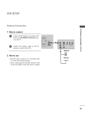
... 3 or 4 and then tune TV to the same channel number. How to use I Insert a video tape into the VCR and press PLAY on the TV. 2 Connect the antenna cable to the VCR owner's manual.) 1 ANT OUT S-VIDEO VIDEO L R AUDIO ANT IN OUTPUT SWITCH Wall Jack 2 Antenna 25 How to... connect 1 Connect the RF antenna out socket of the VCR to the ANTENNA/CABLE IN socket on the VCR. (Refer to the RF antenna in socket of ...
... 3 or 4 and then tune TV to the same channel number. How to use I Insert a video tape into the VCR and press PLAY on the TV. 2 Connect the antenna cable to the VCR owner's manual.) 1 ANT OUT S-VIDEO VIDEO L R AUDIO ANT IN OUTPUT SWITCH Wall Jack 2 Antenna 25 How to... connect 1 Connect the RF antenna out socket of the VCR to the ANTENNA/CABLE IN socket on the VCR. (Refer to the RF antenna in socket of ...

Owners Manual
Page 26
NOTE G If you have a mono VCR, connect the audio cable from the VCR to the VCR owner's manual.) I Select the A V 1 or A V 2 input source on the TV using the INPUT button on the ... to use I Insert a video tape into the VCR and press PLAY on the VCR. (Refer to the AUDIO L/MONO jack of the TV. How to connect 1 Connect the AUDIO/VIDEO jacks between TV and VCR. PREPARATION PREPARATION Composite (RCA...
NOTE G If you have a mono VCR, connect the audio cable from the VCR to the VCR owner's manual.) I Select the A V 1 or A V 2 input source on the TV using the INPUT button on the ... to use I Insert a video tape into the VCR and press PLAY on the VCR. (Refer to the AUDIO L/MONO jack of the TV. How to connect 1 Connect the AUDIO/VIDEO jacks between TV and VCR. PREPARATION PREPARATION Composite (RCA...

Owners Manual
Page 27
PREPARATION OTHER A/V SOURCE SETUP 1. I Select the A V 1 or A V 2 input source on the TV using the INPUT button on the remote control. USB IN Camcorder Video Game Set VIDEO L R 1 VIDEO L/MONO AUDIO R AV IN 2 27 Match the jack colors. (Video = yellow, Audio Left = white, and Audio Right = red) 2. How to connect 1 Connect the AUDIO/VIDEO jacks between TV and external equipment. How to use I Operate the corresponding external equipment.
PREPARATION OTHER A/V SOURCE SETUP 1. I Select the A V 1 or A V 2 input source on the TV using the INPUT button on the remote control. USB IN Camcorder Video Game Set VIDEO L R 1 VIDEO L/MONO AUDIO R AV IN 2 27 Match the jack colors. (Video = yellow, Audio Left = white, and Audio Right = red) 2. How to connect 1 Connect the AUDIO/VIDEO jacks between TV and external equipment. How to use I Operate the corresponding external equipment.
Owners Manual
Page 28
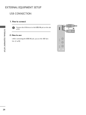
How to the USB I N jack, you use I After connecting the USB I N jack on the side of TV. 2. How to connect 1 Connect the USB device to use the USB function. (G p.54) VIDEO L/MONO AUDIO R USB IN or 1 Memory Key AV IN 2 EXTERNAL EQUIPMENT SETUP 28 EXTERNAL EQUIPMENT SETUP USB CONNECTION 1.
How to the USB I N jack, you use I After connecting the USB I N jack on the side of TV. 2. How to connect 1 Connect the USB device to use the USB function. (G p.54) VIDEO L/MONO AUDIO R USB IN or 1 Memory Key AV IN 2 EXTERNAL EQUIPMENT SETUP 28 EXTERNAL EQUIPMENT SETUP USB CONNECTION 1.
Owners Manual
Page 29
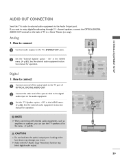
... your vision. G Audio with external audio equipments, such as amplifiers or speakers, you want to enjoy digital broadcasting through 5.1-channel speakers, connect the OPTICAL DIGITAL AUDIO OUT terminal on the audio equipment. 3 Set the "TV Speaker option - Looking at the laser beam may block...) 2 CAUTION G Do not look into the optical output port. On" in the AUDIO menu. (G p.82). Digital 1. How to connect L R 1 Connect audio outputs to external audio equipment via the Audio Output port. See the external audio equipment instruc- EXTERNAL EQUIPMENT SETUP AUDIO OUT...
... your vision. G Audio with external audio equipments, such as amplifiers or speakers, you want to enjoy digital broadcasting through 5.1-channel speakers, connect the OPTICAL DIGITAL AUDIO OUT terminal on the audio equipment. 3 Set the "TV Speaker option - Looking at the laser beam may block...) 2 CAUTION G Do not look into the optical output port. On" in the AUDIO menu. (G p.82). Digital 1. How to connect L R 1 Connect audio outputs to external audio equipment via the Audio Output port. See the external audio equipment instruc- EXTERNAL EQUIPMENT SETUP AUDIO OUT...
Owners Manual
Page 30
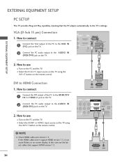
... connect 1 Connect the VGA output of the PC to the HDMI/DVI I N 1or HDMI 2 jack on the TV. 2 Connect the PC audio output to use I Select the RGB-PC input source on the TV using the INPUT button on the TV. 2. I Turn on the PC and the TV. If the HDMI cables don't support HDMI version... 1.3, it can cause flickers or no screen display. NOTE G Check HDMI cable over version 1.3. How to connect 1 Connect the DVI output of the PC to the RGB IN (P C) jack on the TV...
... connect 1 Connect the VGA output of the PC to the HDMI/DVI I N 1or HDMI 2 jack on the TV. 2 Connect the PC audio output to use I Select the RGB-PC input source on the TV using the INPUT button on the TV. 2. I Turn on the PC and the TV. If the HDMI cables don't support HDMI version... 1.3, it can cause flickers or no screen display. NOTE G Check HDMI cable over version 1.3. How to connect 1 Connect the DVI output of the PC to the RGB IN (P C) jack on the TV...


