Owner's Manual (English)
Page 1
... STAR Partner LGE U. A.,Inc. Retain it for energy efficiency. Environmental Protection Agency(EPA). LCD TV PLASMA TV OWNER'S MANUAL LCD TV MODELS 32LC7D 32LC7DC 37LC7D 42LC7D PLASMA TV MODELS 42PC5D 42PC5DC 50PC5D 50PC5DC Please read this manual carefully before operating your dealer when you require service.... S. www.lgusa.com / www.lg.ca / www.lgcommercial.com has determined that...
... STAR Partner LGE U. A.,Inc. Retain it for energy efficiency. Environmental Protection Agency(EPA). LCD TV PLASMA TV OWNER'S MANUAL LCD TV MODELS 32LC7D 32LC7DC 37LC7D 42LC7D PLASMA TV MODELS 42PC5D 42PC5DC 50PC5D 50PC5DC Please read this manual carefully before operating your dealer when you require service.... S. www.lgusa.com / www.lg.ca / www.lgcommercial.com has determined that...
Owner's Manual (English)
Page 9
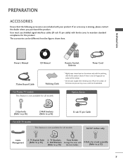
...169; 2007 LGE, All Rights Reserved. For Plasma TV models This feature is not available for all models 32/37 inches only Cable Management 2- ENU ENTER RATIO SIMPLINK CH BRIGHT + TV INPUT TV AUDIO POWER CAMBOLEDDVED INPUT VCR STB BRIGHT - TV Bracket Bolts 2- Wall Brackets Arrange the wires with your...signal interface cables (D-sub 15 pin cable) with the polishing cloth for all models Option Extras 2-Eye-bolts (Refer to p.16) 2-Wall brackets (Refer to p.16) D-sub 15 pin Cable For LCD TV models This feature is not available for the product exterior if there is missing,...
...169; 2007 LGE, All Rights Reserved. For Plasma TV models This feature is not available for all models 32/37 inches only Cable Management 2- ENU ENTER RATIO SIMPLINK CH BRIGHT + TV INPUT TV AUDIO POWER CAMBOLEDDVED INPUT VCR STB BRIGHT - TV Bracket Bolts 2- Wall Brackets Arrange the wires with your...signal interface cables (D-sub 15 pin cable) with the polishing cloth for all models Option Extras 2-Eye-bolts (Refer to p.16) 2-Wall brackets (Refer to p.16) D-sub 15 pin Cable For LCD TV models This feature is not available for the product exterior if there is missing,...
Owner's Manual (English)
Page 10
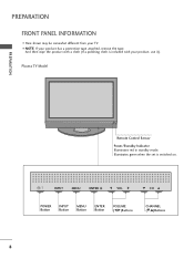
I Here shown may be somewhat different from your TV. INPUT MENU ENTER VOL CH INPUT MENU ENTER VOL CH POWER Button INPUT Button MENU Button ENTER Button VOLUME (F,G)Buttons CHANNEL (E,D)Buttons 8 And then wipe the product with your product, use it). Plasma TV Model PREPARATION Remote Control Sensor Power/Standby Indicator Illuminates red in standby mode. Illuminates green when the set is included with a cloth (If a polishing cloth is switched on. PREPARATION FRONT PANEL INFORMATION I NOTE: If your product has a protection tape attached, remove the tape.
I Here shown may be somewhat different from your TV. INPUT MENU ENTER VOL CH INPUT MENU ENTER VOL CH POWER Button INPUT Button MENU Button ENTER Button VOLUME (F,G)Buttons CHANNEL (E,D)Buttons 8 And then wipe the product with your product, use it). Plasma TV Model PREPARATION Remote Control Sensor Power/Standby Indicator Illuminates red in standby mode. Illuminates green when the set is included with a cloth (If a polishing cloth is switched on. PREPARATION FRONT PANEL INFORMATION I NOTE: If your product has a protection tape attached, remove the tape.
Owner's Manual (English)
Page 11
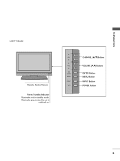
CH VOL ENTER MENU INPUT CH VOL ENTER MENU INPUT CHANNEL (D,E)Buttons VOLUME (F,G)Buttons ENTER Button MENU Button INPUT Button POWER Button 9 PREPARATION LCD TV Model Remote Control Sensor Power/Standby Indicator Illuminates red in standby mode. Illuminates green when the set is switched on.
CH VOL ENTER MENU INPUT CH VOL ENTER MENU INPUT CHANNEL (D,E)Buttons VOLUME (F,G)Buttons ENTER Button MENU Button INPUT Button POWER Button 9 PREPARATION LCD TV Model Remote Control Sensor Power/Standby Indicator Illuminates red in standby mode. Illuminates green when the set is switched on.
Owner's Manual (English)
Page 14
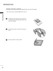
PREPARATION PREPARATION STAND INSTALLATION (Only 32/37 inches LCD TV models) I Here shown may be somewhat different from your TV. 1 Carefully place the product screen side down on a cushioned surface that will protect product and screen from damage. 2 Assemble the product stand with the product as shown. 3 Securely install the 4 bolts provided. 12
PREPARATION PREPARATION STAND INSTALLATION (Only 32/37 inches LCD TV models) I Here shown may be somewhat different from your TV. 1 Carefully place the product screen side down on a cushioned surface that will protect product and screen from damage. 2 Assemble the product stand with the product as shown. 3 Securely install the 4 bolts provided. 12
Owner's Manual (English)
Page 15
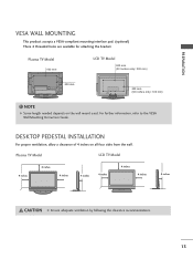
...: 100 mm) ! PREPARATION VESA WALL MOUNTING This product accepts a VESA-compliant mounting interface pad. (optional) There 4 threaded holes are available for attaching the bracket. Plasma TV Model LCD TV Model 4 inches 4 inches 4 inches 4 inches 4 inches 4 inches 4 inches 4 inches CAUTION G Ensure adequate ventilation by following the clearance recommendations. 13 For further information, refer to the VESA...
...: 100 mm) ! PREPARATION VESA WALL MOUNTING This product accepts a VESA-compliant mounting interface pad. (optional) There 4 threaded holes are available for attaching the bracket. Plasma TV Model LCD TV Model 4 inches 4 inches 4 inches 4 inches 4 inches 4 inches 4 inches 4 inches CAUTION G Ensure adequate ventilation by following the clearance recommendations. 13 For further information, refer to the VESA...
Owner's Manual (English)
Page 16
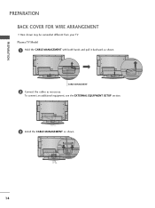
PREPARATION PREPARATION BACK COVER FOR WIRE ARRANGEMENT I Here shown may be somewhat different from your TV. CABLE MANAGEMENT 2 Connect the cables as shown. 14 To connect an additional equipment, see the EXTERNAL EQUIPMENT SETUP section. 3 Install the CABLE MANAGEMENT as necessary. Plasma TV Model 1 Hold the CABLE MANAGEMENT with both hands and pull it backward as shown.
PREPARATION PREPARATION BACK COVER FOR WIRE ARRANGEMENT I Here shown may be somewhat different from your TV. CABLE MANAGEMENT 2 Connect the cables as shown. 14 To connect an additional equipment, see the EXTERNAL EQUIPMENT SETUP section. 3 Install the CABLE MANAGEMENT as necessary. Plasma TV Model 1 Hold the CABLE MANAGEMENT with both hands and pull it backward as shown.
Owner's Manual (English)
Page 17
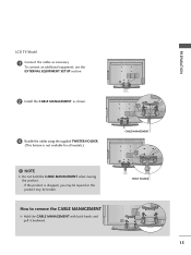
How to remove the CABLE MANAGEMENT G Hold the CABLE MANAGEMENT with both hands and pull it backward. NOTE G Do not hold the CABLE MANAGEMENT when moving the product. - If the product is not available for all models.) CABLE MANAGEMENT ! PREPARATION LCD TV Model 1 Connect the cables as shown. 3 Bundle the cables using the supplied TWISTER HOLDER. (This feature is dropped, you may be injured or the product may be broken. TWIST HOLDER 15 To connect an additional equipment, see the EXTERNAL EQUIPMENT SETUP section. 2 Install the CABLE MANAGEMENT as necessary.
How to remove the CABLE MANAGEMENT G Hold the CABLE MANAGEMENT with both hands and pull it backward. NOTE G Do not hold the CABLE MANAGEMENT when moving the product. - If the product is not available for all models.) CABLE MANAGEMENT ! PREPARATION LCD TV Model 1 Connect the cables as shown. 3 Bundle the cables using the supplied TWISTER HOLDER. (This feature is dropped, you may be injured or the product may be broken. TWIST HOLDER 15 To connect an additional equipment, see the EXTERNAL EQUIPMENT SETUP section. 2 Install the CABLE MANAGEMENT as necessary.
Owner's Manual (English)
Page 18
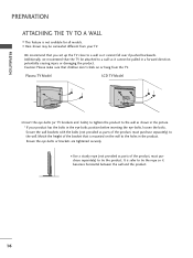
Ensure the eye-bolts or brackets are tightened securely. I Here shown may be pulled in the picture. * If your TV. Plasma TV Model LCD TV Model I Insert the eye-bolts (or TV brackets and bolts) to tighten the product to the wall as shown in a forward direction, potentially causing injury or damaging the product. ...to a wall so it cannot fall over if pushed backwards. We recommend that the TV be attached to tie the product. It is not available for all models. Additionally, we recommend that you set up the TV close to tie the rope so it cannot be somewhat different from the...
Ensure the eye-bolts or brackets are tightened securely. I Here shown may be pulled in the picture. * If your TV. Plasma TV Model LCD TV Model I Insert the eye-bolts (or TV brackets and bolts) to tighten the product to the wall as shown in a forward direction, potentially causing injury or damaging the product. ...to a wall so it cannot fall over if pushed backwards. We recommend that the TV be attached to tie the product. It is not available for all models. Additionally, we recommend that you set up the TV close to tie the rope so it cannot be somewhat different from the...
Owner's Manual (English)
Page 20
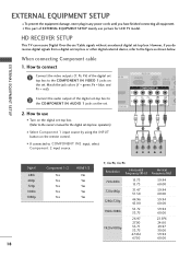
...) AUDIO REM (RGB/DVI) SERVICE CONT COMPONENT IN 2 RS (CONTR 2 Connect the audio output of the digital set top box to the owner's manual for LCD TV model. Match the jack colors (Y = green, PB = blue, and PR = red). operation) I Select Component 1 input source by using the INPUT button on the remote control. ...a digital set-top box or other digital external device, refer to COMPONENT IN2 input, select Component 2 input source. HD RECEIVER SETUP This TV can receive Digital Over-the-air/Cable signals without an external digital set . How to use picture for the digital set .
...) AUDIO REM (RGB/DVI) SERVICE CONT COMPONENT IN 2 RS (CONTR 2 Connect the audio output of the digital set top box to the owner's manual for LCD TV model. Match the jack colors (Y = green, PB = blue, and PR = red). operation) I Select Component 1 input source by using the INPUT button on the remote control. ...a digital set-top box or other digital external device, refer to COMPONENT IN2 input, select Component 2 input source. HD RECEIVER SETUP This TV can receive Digital Over-the-air/Cable signals without an external digital set . How to use picture for the digital set .
Owner's Manual (English)
Page 25
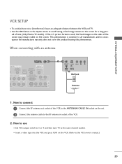
...R ANT IN OUTPUT SWITCH 2 Wall Jack Antenna 1. I Set VCR output switch to 3 or 4 and then tune TV to the same channel number. the fixed images on the sides of time (Only Plasma TV model). This phenomenon is used; I To avoid picture noise (interference), leave an adequate distance between the VCR and... TV. If the 4:3 picture format is common to all manufactures and in the Option menu to ...
...R ANT IN OUTPUT SWITCH 2 Wall Jack Antenna 1. I Set VCR output switch to 3 or 4 and then tune TV to the same channel number. the fixed images on the sides of time (Only Plasma TV model). This phenomenon is used; I To avoid picture noise (interference), leave an adequate distance between the VCR and... TV. If the 4:3 picture format is common to all manufactures and in the Option menu to ...
Owner's Manual (English)
Page 37
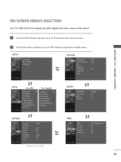
... OPTION Language Input Label SimpLink Key Lock Caption ISM Method Low Power Set ID : English : Off : Off : Off : Orbiter : Off : 1 Only Plasma TV model AUDIO Sound Mode Auto Volume Balance TV Speaker : Standard : On : 0 : On TIME Clock Off Time On Time Sleep Time Auto Sleep : Oct 19, 2006, 03:44 AM : Off : Off... : Off : Off 35 ON-SCREEN MENUS SELECTION Your TV's OSD (On Screen Display) may differ slightly from what is shown in this manual. 1 Press the MENU button and then use D or E button to select...
... OPTION Language Input Label SimpLink Key Lock Caption ISM Method Low Power Set ID : English : Off : Off : Off : Orbiter : Off : 1 Only Plasma TV model AUDIO Sound Mode Auto Volume Balance TV Speaker : Standard : On : 0 : On TIME Clock Off Time On Time Sleep Time Auto Sleep : Oct 19, 2006, 03:44 AM : Off : Off... : Off : Off 35 ON-SCREEN MENUS SELECTION Your TV's OSD (On Screen Display) may differ slightly from what is shown in this manual. 1 Press the MENU button and then use D or E button to select...
Owner's Manual (English)
Page 83
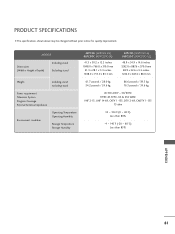
PRODUCT SPECIFICATIONS I The specifications shown above may be changed without prior notice for quality improvement. MODELS Dimensions (Width x Height x Depth) Including stand Excluding stand Weight including stand excluding stand Power requirement Television System Program Coverage External Antenna Impedance Environment condition Operating ...
PRODUCT SPECIFICATIONS I The specifications shown above may be changed without prior notice for quality improvement. MODELS Dimensions (Width x Height x Depth) Including stand Excluding stand Weight including stand excluding stand Power requirement Television System Program Coverage External Antenna Impedance Environment condition Operating ...

Owner's Manual (English)
Page 84
APPENDIX MODELS Dimensions (Width x Height x Depth) Including stand Excluding stand 32LC7D (32LC7D-UK) 32LC7DC (32LC7DC-UK) 37LC7D (37LC7D-UK) 42LC7D (42LC7D-UK) 31.8 x 23.9x 9.8 inches 806.6 x 606.5 x 249.0mm 31.8 x 21.7 x 3.1 inches 806.6 x 552.3 x 79.0 mm 36.5 x 27.3 x 11.0 inches 40.7 x 29.5 x 11.3 inches 927.0 x ...
APPENDIX MODELS Dimensions (Width x Height x Depth) Including stand Excluding stand 32LC7D (32LC7D-UK) 32LC7DC (32LC7DC-UK) 37LC7D (37LC7D-UK) 42LC7D (42LC7D-UK) 31.8 x 23.9x 9.8 inches 806.6 x 606.5 x 249.0mm 31.8 x 21.7 x 3.1 inches 806.6 x 552.3 x 79.0 mm 36.5 x 27.3 x 11.0 inches 40.7 x 29.5 x 11.3 inches 927.0 x ...
Owner's Manual (English)
Page 85
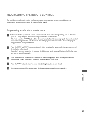
.... 5 Test the remote control functions to see if the device responds properly. The program- If not, steps 2-5. After that the remote may not control all models of other brands. Note that , press the POWER button. Programming a code into a remote mode 1 To find out whether your remote control can be programmed to...
.... 5 Test the remote control functions to see if the device responds properly. The program- If not, steps 2-5. After that the remote may not control all models of other brands. Note that , press the POWER button. Programming a code into a remote mode 1 To find out whether your remote control can be programmed to...
Owner's Manual (English)
Page 93
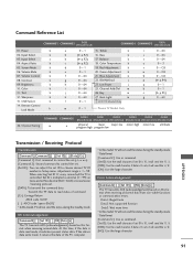
... the standby mode. * Data Format [Command 2]: Use as Hexa decimal (0x0~0x63) on this format when receiving normal data. Key m k 0 ~ 64 27. Back Light m l 0~1 LCD TV Model Only m 0~1 Plasma TV Model Only r 0 ~ 64 s 0 ~ 64 t 0 ~ 64 u 0~3 v 0 ~ C8 w 0 ~ C8 $ 0 ~ C8 p (G p.94) q 0~1 b 0~1 c ... x ab, it indicates present status data. Data1: Illegal Code Data2: Not supported function Data3: Wait more time * In this model, TV will send the 'a', 'b'. [OK]: Use the large character. Volume Control k 08. Adjustment range is controlled. Input Select x...
... the standby mode. * Data Format [Command 2]: Use as Hexa decimal (0x0~0x63) on this format when receiving normal data. Key m k 0 ~ 64 27. Back Light m l 0~1 LCD TV Model Only m 0~1 Plasma TV Model Only r 0 ~ 64 s 0 ~ 64 t 0 ~ 64 u 0~3 v 0 ~ C8 w 0 ~ C8 $ 0 ~ C8 p (G p.94) q 0~1 b 0~1 c ... x ab, it indicates present status data. Data1: Illegal Code Data2: Not supported function Data3: Wait more time * In this model, TV will send the 'a', 'b'. [OK]: Use the large character. Volume Control k 08. Adjustment range is controlled. Input Select x...

Owner's Manual (English)
Page 94
... [b][ ][Set ID][ ][OK/NG][Data][x] 04. Volume Mute (Command: k e) To control volume mute on /off . Power (Command: k a) To control Power On/Off of the TV. Transmission [k][b][ ][Set ID][ ][Data][Cr] Data 0: DTV Data 1: Analog Data 2: AV1 Data 3: AV2 Data 4: Component 1 Data 5: Component 2 Data 7: RGB-PC Data 8: HDMI1... like manner, if other functions transmit 'FF' data based on this format, Acknowledgement data feedback presents status about each function. * Note: In this model, TV will send the Acknowledge after power on remote control or in the Picture menu.
... [b][ ][Set ID][ ][OK/NG][Data][x] 04. Volume Mute (Command: k e) To control volume mute on /off . Power (Command: k a) To control Power On/Off of the TV. Transmission [k][b][ ][Set ID][ ][Data][Cr] Data 0: DTV Data 1: Analog Data 2: AV1 Data 3: AV2 Data 4: Component 1 Data 5: Component 2 Data 7: RGB-PC Data 8: HDMI1... like manner, if other functions transmit 'FF' data based on this format, Acknowledgement data feedback presents status about each function. * Note: In this model, TV will send the Acknowledge after power on remote control or in the Picture menu.

Owner's Manual (English)
Page 96
...2: Major Channel Number Data1: High byte Data2: Low byte Two bytes are available for NTSC. ISM Method (Command: j p) (Only Plasma TV model) To avoid having a fixed image remain on Acknowledgement [q][ ][Set ID][ ][OK/NG][Data][x] 24. See page 93. Low Power (Command: j q) (Only... Plasma TV model) To control the low power function on/off 1: Low Power on screen. Transmission [m][a][ ][Set ID][ ][Data0][ ][Data1] [ ][Data2][ ][Data3][ ][...
...2: Major Channel Number Data1: High byte Data2: Low byte Two bytes are available for NTSC. ISM Method (Command: j p) (Only Plasma TV model) To avoid having a fixed image remain on Acknowledgement [q][ ][Set ID][ ][OK/NG][Data][x] 24. See page 93. Low Power (Command: j q) (Only... Plasma TV model) To control the low power function on/off 1: Low Power on screen. Transmission [m][a][ ][Set ID][ ][Data0][ ][Data1] [ ][Data2][ ][Data3][ ][...

Owner's Manual (English)
Page 97
... signal type. * Tune Command Examples: 1. Tune to the digital (ATSC) local channel 30-3. Tune to the analog (NTSC) cable channel 35. Back Light (Command: m g) (Only LCD TV model) To adjust screen back light. Data 0 = Physical of 35 = 23 Data 1 & 2 = No Major = 00 00 Data 3 & 4 = No Minor = 00 00 Data 5 = 0000 0001 in Hex...
... signal type. * Tune Command Examples: 1. Tune to the digital (ATSC) local channel 30-3. Tune to the analog (NTSC) cable channel 35. Back Light (Command: m g) (Only LCD TV model) To adjust screen back light. Data 0 = Physical of 35 = 23 Data 1 & 2 = No Major = 00 00 Data 3 & 4 = No Minor = 00 00 Data 5 = 0000 0001 in Hex...


