User Manual
Page 2
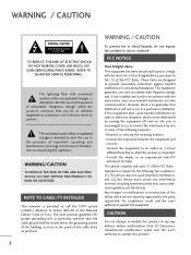
...SERVICE PERSONNEL. The lightning flash with the instructions, may be determined by turning the equipment off and on a circuit different from LG Electronics. Consult the dealer or an experienced radio/TV technician for proper grounding and, in accordance with arrowhead symbol, within an ... receiver. - Reorient or relocate the receiving antenna. - This equipment generates, uses and can be of sufficient magnitude to persons. Connect the equipment to an outlet on , the user is no guarantee that interference will not occur in any interference received, including interference...
...SERVICE PERSONNEL. The lightning flash with the instructions, may be determined by turning the equipment off and on a circuit different from LG Electronics. Consult the dealer or an experienced radio/TV technician for proper grounding and, in accordance with arrowhead symbol, within an ... receiver. - Reorient or relocate the receiving antenna. - This equipment generates, uses and can be of sufficient magnitude to persons. Connect the equipment to an outlet on , the user is no guarantee that interference will not occur in any interference received, including interference...
User Manual
Page 4
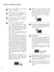
...with the power cord plugged in electric shock or fire. a TV with an exact replacement part by an authorized servicer. The plug must be connected to be placed upon . Overloaded wall outlets, loose or damaged wall outlets, extension cords, frayed power cords, or damaged or cracked wire ...vases, cups, etc. Do not install this owner's manual to a three-prong grounded AC outlet). Do not try to ground the unit by connecting it , discontinue use a damaged or loose power cord. Short-circuit Breaker Power Supply 18 DISCONNECTING DEVICE FROM MAINS Mains plug is recommend that ...
...with the power cord plugged in electric shock or fire. a TV with an exact replacement part by an authorized servicer. The plug must be connected to be placed upon . Overloaded wall outlets, loose or damaged wall outlets, extension cords, frayed power cords, or damaged or cracked wire ...vases, cups, etc. Do not install this owner's manual to a three-prong grounded AC outlet). Do not try to ground the unit by connecting it , discontinue use a damaged or loose power cord. Short-circuit Breaker Power Supply 18 DISCONNECTING DEVICE FROM MAINS Mains plug is recommend that ...
User Manual
Page 5
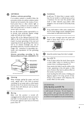
... dusty places. 24 If you smell smoke or other electric light or power circuits, or where it for long periods of antenna discharge unit, connection to the touch, there may be located in the vicinity of overhead power lines or other odors coming from direct sunlight. 27 For.... Doing so may occur. Do not press against it can occur. Disposal of the TV. 23 Ventilation Install your local authority. 5 Avoid touching the LCD screen or holding your finger(s) against or put stress on the front panel of this product with a soft cloth to carry larger TVs. An outdoor...
... dusty places. 24 If you smell smoke or other electric light or power circuits, or where it for long periods of antenna discharge unit, connection to the touch, there may be located in the vicinity of overhead power lines or other odors coming from direct sunlight. 27 For.... Doing so may occur. Do not press against it can occur. Disposal of the TV. 23 Ventilation Install your local authority. 5 Avoid touching the LCD screen or holding your finger(s) against or put stress on the front panel of this product with a soft cloth to carry larger TVs. An outdoor...
User Manual
Page 6
... List 45 Favorite Channel Setup / Favorite Channel List . . 46 Brief Information 47 Input List 48 Input Label 49 AV Mode 50 SIMPLINK 51 USB Entry Modes 54 Photo List 55 Music List 59 PICTURE CONTROL Picture Size (Aspect Ratio) Control 62 Picture Wizard 64 Preset Picture Settings (Picture Mode... EXTERNAL EQUIPMENT SETUP HD Receiver Setup 20 DVD Setup 23 VCR Setup 25 Other A/V Source Setup 27 USB Connection 28 Audio out Connection 29 PC Setup 30 WATCHING TV / CHANNEL CONTROL Remote Control Functions 36 Turning On TV 38 Channel Selection 38 Volume Adjustment 38 Initial ...
... List 45 Favorite Channel Setup / Favorite Channel List . . 46 Brief Information 47 Input List 48 Input Label 49 AV Mode 50 SIMPLINK 51 USB Entry Modes 54 Photo List 55 Music List 59 PICTURE CONTROL Picture Size (Aspect Ratio) Control 62 Picture Wizard 64 Preset Picture Settings (Picture Mode... EXTERNAL EQUIPMENT SETUP HD Receiver Setup 20 DVD Setup 23 VCR Setup 25 Other A/V Source Setup 27 USB Connection 28 Audio out Connection 29 PC Setup 30 WATCHING TV / CHANNEL CONTROL Remote Control Functions 36 Turning On TV 38 Channel Selection 38 Volume Adjustment 38 Initial ...
User Manual
Page 9
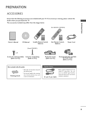
Option Extras D-sub 15 pin Cable When using the VGA (D-sub 15 pin cable) PC connection, the user must use shielded signal interface cables with ferrite cores to P.15) Not included with all models Polishing Cloth * Wipe spots on the exterior ...
Option Extras D-sub 15 pin Cable When using the VGA (D-sub 15 pin cable) PC connection, the user must use shielded signal interface cables with ferrite cores to P.15) Not included with all models Polishing Cloth * Wipe spots on the exterior ...
User Manual
Page 11
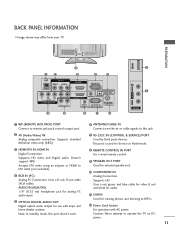
... home theater systems. Note: In standby mode, this jack. 2 AV (Audio/Video) IN Analog composite connection. Uses a D-sub 15 pin cable (VGA cable). Accepts DVI video using an adapter or HDMI to operate the TV on DC power. 11 Caution: Never attempt to DVI cable (not included). 4 RGB... & red and white for audio. 11 USB IN Used for viewing photos and listening to this port doesn't work. 8 REMOTE CONTROL IN PORT For a wired remote control. 9 SPEAKER OUT PORT Used for Service or Hotel mode. 3 HDMI/DVI IN, HDMI IN Digital Connection. Supports standard definition video only (480i). ...
... home theater systems. Note: In standby mode, this jack. 2 AV (Audio/Video) IN Analog composite connection. Uses a D-sub 15 pin cable (VGA cable). Accepts DVI video using an adapter or HDMI to operate the TV on DC power. 11 Caution: Never attempt to DVI cable (not included). 4 RGB... & red and white for audio. 11 USB IN Used for viewing photos and listening to this port doesn't work. 8 REMOTE CONTROL IN PORT For a wired remote control. 9 SPEAKER OUT PORT Used for Service or Hotel mode. 3 HDMI/DVI IN, HDMI IN Digital Connection. Supports standard definition video only (480i). ...

User Manual
Page 15
... SCREW as necessary. NOTE G Do not hold the CABLE MANAGEMENT CLIP when moving the TV. - It will help prevent the power cable from your TV. 1 Connect the cables as shown. If the TV is dropped, you may be injured or the product may differ from being removed by accident. 2 Install the...
... SCREW as necessary. NOTE G Do not hold the CABLE MANAGEMENT CLIP when moving the TV. - It will help prevent the power cable from your TV. 1 Connect the cables as shown. If the TV is dropped, you may be injured or the product may differ from being removed by accident. 2 Install the...

User Manual
Page 16
... provided with a Kensington Security System connector on all models. - Kensington sells security systems for all four sides from your viewing position. Connect the Kensington Security System cable as notebook PCs and LCD projectors. PREPARATION PREPARATION DESKTOP PEDESTAL INSTALLATION I This feature is not available for expensive electronic equipment such as shown below. - G Do...
... provided with a Kensington Security System connector on all models. - Kensington sells security systems for all four sides from your viewing position. Connect the Kensington Security System cable as notebook PCs and LCD projectors. PREPARATION PREPARATION DESKTOP PEDESTAL INSTALLATION I This feature is not available for expensive electronic equipment such as shown below. - G Do...
User Manual
Page 19
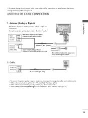
...and Digital TV. 19 Cable Cable TV Wall Jack RF Coaxial Wire (75 ohm) ACNATBELNENIAN/ I To prevent damage do not connect to bend the copper wire when connecting the antenna. 2. For optimum picture quality, adjust antenna direction if needed. I If the antenna needs to be split for ...outdoor antenna) Copper Wire Be careful not to the power outlet until all connections are made between the devices. PREPARATION I To improve the picture quality in a poor signal area, please purchase a signal amplifier and install properly...
...and Digital TV. 19 Cable Cable TV Wall Jack RF Coaxial Wire (75 ohm) ACNATBELNENIAN/ I To prevent damage do not connect to bend the copper wire when connecting the antenna. 2. For optimum picture quality, adjust antenna direction if needed. I If the antenna needs to be split for ...outdoor antenna) Copper Wire Be careful not to the power outlet until all connections are made between the devices. PREPARATION I To improve the picture quality in a poor signal area, please purchase a signal amplifier and install properly...
User Manual
Page 20
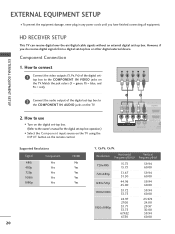
... equipment damage, never plug in any power cords until you do receive digital signals from a digital set -top box. How to connect 1 Connect the video outputs (Y, PB, PR) of the digital set-top box to the COMPONENT IN VIDEO jacks on the TV. EXTERNAL EQUIPMENT... 1 VIDEO COMPONENT IN L AUDIO R L R SPEAKER OUT /DVI IN REMO CONTRO Supported Resolutions Signal Component 480i Yes 480p Yes 720p Yes 1080i Yes 1080p Yes HDMI No Yes Yes Yes Yes 20 Y, CB/PB, CR/PR Resolution Horizontal Vertical Frequency(KHz) Frequency(Hz) 720x480i 720x480p 1280x720p 1920x1080i 1920x1080p...
... equipment damage, never plug in any power cords until you do receive digital signals from a digital set -top box. How to connect 1 Connect the video outputs (Y, PB, PR) of the digital set-top box to the COMPONENT IN VIDEO jacks on the TV. EXTERNAL EQUIPMENT... 1 VIDEO COMPONENT IN L AUDIO R L R SPEAKER OUT /DVI IN REMO CONTRO Supported Resolutions Signal Component 480i Yes 480p Yes 720p Yes 1080i Yes 1080p Yes HDMI No Yes Yes Yes Yes 20 Y, CB/PB, CR/PR Resolution Horizontal Vertical Frequency(KHz) Frequency(Hz) 720x480i 720x480p 1280x720p 1920x1080i 1920x1080p...
User Manual
Page 21
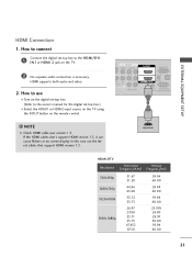
...23.976 24.00 29.97 30.00 59.94 60.00 21 How to connect 1 Connect the digital set-top box to the owner's manual for the digital set -top box. (Refer to the HDMI/DVI I Select the HDMI1 or HDMI2 input source on the TV using the INPUT...2 No separate audio connection is necessary. How to use the latest cables that support HDMI version 1.3. In this case use I Turn on the digital set -top box.) I N 1or HDMI 2 jack on the remote control. ! HDMI supports both audio and video. 2. EXTERNAL EQUIPMENT SETUP HDMI Connection 1. If the HDMI cables don't support HDMI version 1.3, it can...
...23.976 24.00 29.97 30.00 59.94 60.00 21 How to connect 1 Connect the digital set-top box to the owner's manual for the digital set -top box. (Refer to the HDMI/DVI I Select the HDMI1 or HDMI2 input source on the TV using the INPUT...2 No separate audio connection is necessary. How to use the latest cables that support HDMI version 1.3. In this case use I Turn on the digital set -top box.) I N 1or HDMI 2 jack on the remote control. ! HDMI supports both audio and video. 2. EXTERNAL EQUIPMENT SETUP HDMI Connection 1. If the HDMI cables don't support HDMI version 1.3, it can...
User Manual
Page 22
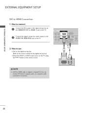
... DVI output of the digital set-top box to the HDMI/DVI IN 1or HDMI 2 jack on the TV. 2 Connect the digital set -top box. (Refer to HDMI cable or adapter is necessary. DVI OUTPUT L R AUDIO 22 EXTERNAL EQUIPMENT SETUP EXTERNAL EQUIPMENT SETUP DVI to the AUDIO IN (RGB/DVI...) jack on the TV. 2. NOTE G A DVI to the owner's manual for this connection. DVI doesn't support audio, so a separate audio connection is required for ...
... DVI output of the digital set-top box to the HDMI/DVI IN 1or HDMI 2 jack on the TV. 2 Connect the digital set -top box. (Refer to HDMI cable or adapter is necessary. DVI OUTPUT L R AUDIO 22 EXTERNAL EQUIPMENT SETUP EXTERNAL EQUIPMENT SETUP DVI to the AUDIO IN (RGB/DVI...) jack on the TV. 2. NOTE G A DVI to the owner's manual for this connection. DVI doesn't support audio, so a separate audio connection is required for ...
User Manual
Page 23
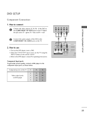
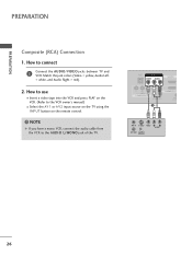
...COMPONENT IN VIDEO jacks on the remote control. How to the DVD player's manual for operating instructions. Component Input ports To get better picture quality, connect a DVD player to the COMPONENT IN AUDIO jacks on the DVD player, insert a DVD. I Refer to use I Turn on the TV. 2. How ...to connect 1 Connect the video outputs (Y, PB, PR) of the DVD to the component input ports as shown below. Component ports on the TV Y Y Video output ports Y on...
...COMPONENT IN VIDEO jacks on the remote control. How to the DVD player's manual for operating instructions. Component Input ports To get better picture quality, connect a DVD player to the COMPONENT IN AUDIO jacks on the DVD player, insert a DVD. I Refer to use I Turn on the TV. 2. How ...to connect 1 Connect the video outputs (Y, PB, PR) of the DVD to the component input ports as shown below. Component ports on the TV Y Y Video output ports Y on...
User Manual
Page 24
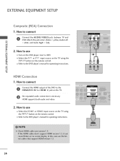
..., and Audio Right = red). 2. I Refer to the DVD player's manual for operating instructions. How to use I Refer to the DVD player's manual for operating instructions. HDMI OUTPUT 24 HDMI Connection 1. In this case use I Select the HDMI1 or HDMI2 input source on the TV using the INPUT button on the remote control...
..., and Audio Right = red). 2. I Refer to the DVD player's manual for operating instructions. How to use I Refer to the DVD player's manual for operating instructions. HDMI OUTPUT 24 HDMI Connection 1. In this case use I Select the HDMI1 or HDMI2 input source on the TV using the INPUT button on the remote control...
User Manual
Page 25
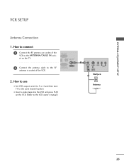
RGB IN (PC) DIO IN GB/DVI) OPTICAL DIGITAL AUDIO OUT RS-232C IN ACNATBELNENIAN/ CONTROL&SERVICE) 2. How to connect 1 Connect the RF antenna out socket of the VCR. I Set VCR output switch to 3 or 4 and then tune TV to the RF antenna in socket of ... VIDEO L R AUDIO ANT IN OUTPUT SWITCH Wall Jack 2 Antenna 25 How to use I Insert a video tape into the VCR and press PLAY on the TV. 2 Connect the antenna cable to the same channel number. EXTERNAL EQUIPMENT SETUP VCR SETUP Antenna...
RGB IN (PC) DIO IN GB/DVI) OPTICAL DIGITAL AUDIO OUT RS-232C IN ACNATBELNENIAN/ CONTROL&SERVICE) 2. How to connect 1 Connect the RF antenna out socket of the VCR. I Set VCR output switch to 3 or 4 and then tune TV to the RF antenna in socket of ... VIDEO L R AUDIO ANT IN OUTPUT SWITCH Wall Jack 2 Antenna 25 How to use I Insert a video tape into the VCR and press PLAY on the TV. 2 Connect the antenna cable to the same channel number. EXTERNAL EQUIPMENT SETUP VCR SETUP Antenna...
User Manual
Page 26
... IN L AUDIO R L R SPEAKER OUT 1 /DVI IN REMO CONTR ANT IN S-VIDEO VIDEO L R AUDIO ANT OUT OUTPUT SWITCH 26 PREPARATION PREPARATION Composite (RCA) Connection 1. NOTE G If you have a mono VCR, connect the audio cable from the VCR to the VCR owner's manual.) I Insert a video tape into the VCR and press PLAY on the...
... IN L AUDIO R L R SPEAKER OUT 1 /DVI IN REMO CONTR ANT IN S-VIDEO VIDEO L R AUDIO ANT OUT OUTPUT SWITCH 26 PREPARATION PREPARATION Composite (RCA) Connection 1. NOTE G If you have a mono VCR, connect the audio cable from the VCR to the VCR owner's manual.) I Insert a video tape into the VCR and press PLAY on the...
User Manual
Page 27
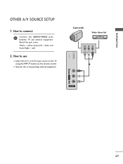
How to use I Operate the corresponding external equipment. How to connect 1 Connect the AUDIO/VIDEO jacks between TV and external equipment. USB IN Camcorder Video Game Set VIDEO L R 1 VIDEO L/MONO AUDIO R AV IN 2 27 I Select the A V 1 or A V 2 input source on the TV using the INPUT button on the remote control. Match the jack colors. (Video = yellow, Audio Left = white, and Audio Right = red) 2. PREPARATION OTHER A/V SOURCE SETUP 1.
How to use I Operate the corresponding external equipment. How to connect 1 Connect the AUDIO/VIDEO jacks between TV and external equipment. USB IN Camcorder Video Game Set VIDEO L R 1 VIDEO L/MONO AUDIO R AV IN 2 27 I Select the A V 1 or A V 2 input source on the TV using the INPUT button on the remote control. Match the jack colors. (Video = yellow, Audio Left = white, and Audio Right = red) 2. PREPARATION OTHER A/V SOURCE SETUP 1.

User Manual
Page 28
EXTERNAL EQUIPMENT SETUP USB CONNECTION 1. How to connect 1 Connect the USB device to use I After connecting the USB I N jack on the side of TV. 2. How to the USB I N jack, you use the USB function. (G p.54) VIDEO L/MONO AUDIO R USB IN or 1 Memory Key AV IN 2 EXTERNAL EQUIPMENT SETUP 28
EXTERNAL EQUIPMENT SETUP USB CONNECTION 1. How to connect 1 Connect the USB device to use I After connecting the USB I N jack on the side of TV. 2. How to the USB I N jack, you use the USB function. (G p.54) VIDEO L/MONO AUDIO R USB IN or 1 Memory Key AV IN 2 EXTERNAL EQUIPMENT SETUP 28

User Manual
Page 29
... - See the external audio equipment instruction manual for operation. Looking at the laser beam may block digital audio output. 29 How to connect L R 1 Connect audio outputs to external audio equipment via the Audio Output port. Digital 1. Off " in the AUDIO menu. (G p.83). G ...Audio with external audio equipments, such as amplifiers or speakers, you want to enjoy digital broadcasting through 5.1-channel speakers, connect the OPTICAL DIGITAL AUDIO OUT terminal on the back of the optical cable to a Home Theater (or amp). tion manual for operation. ! ...
... - See the external audio equipment instruction manual for operation. Looking at the laser beam may block digital audio output. 29 How to connect L R 1 Connect audio outputs to external audio equipment via the Audio Output port. Digital 1. Off " in the AUDIO menu. (G p.83). G ...Audio with external audio equipments, such as amplifiers or speakers, you want to enjoy digital broadcasting through 5.1-channel speakers, connect the OPTICAL DIGITAL AUDIO OUT terminal on the back of the optical cable to a Home Theater (or amp). tion manual for operation. ! ...
User Manual
Page 30
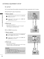
... PC and the TV. I Turn on the remote control. ! If the HDMI cables don't support HDMI version 1.3, it can cause flickers or no screen display. How to connect 1 Connect the VGA output of the PC to the HDMI/DVI I N 1or HDMI 2 jack on the TV. 2 Connect the PC audio output to the AUDIO IN (RGB/DVI) jack on...
... PC and the TV. I Turn on the remote control. ! If the HDMI cables don't support HDMI version 1.3, it can cause flickers or no screen display. How to connect 1 Connect the VGA output of the PC to the HDMI/DVI I N 1or HDMI 2 jack on the TV. 2 Connect the PC audio output to the AUDIO IN (RGB/DVI) jack on...


