

Owner's Manual (English)
Page 1
www.lgcommercial.com See the label attached on the back cover and quote t tion to your set . Record model number and serial number of the set . Retain it for future reference. LCD TV PLASMA TV OWNER'S MANUAL LCD TV MODELS PLASMA TV MODEL 32LC5DC 32LC50C 42PX8DC 32LC5DCS 32LC50CS 32LC5DCB 32LC50CB 37LC5DC 32LX50C 37LC5DCB 32LX50CS 37LC5DC1 37LC50C 42LC5DC 37LC50CB 32LX5DC 42LB50C 32LX5DCS 42LC50C 42LB5DC Please read this manual carefully before operating your dealer when you require service.
www.lgcommercial.com See the label attached on the back cover and quote t tion to your set . Record model number and serial number of the set . Retain it for future reference. LCD TV PLASMA TV OWNER'S MANUAL LCD TV MODELS PLASMA TV MODEL 32LC5DC 32LC50C 42PX8DC 32LC5DCS 32LC50CS 32LC5DCB 32LC50CB 37LC5DC 32LX50C 37LC5DCB 32LX50CS 37LC5DC1 37LC50C 42LC5DC 37LC50CB 32LX5DC 42LB50C 32LX5DCS 42LC50C 42LB5DC Please read this manual carefully before operating your dealer when you require service.
Owner's Manual (English)
Page 3
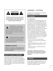
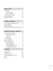
.../CAUTION TO REDUCE THE RISK OF FIRE AND ELECTRIC SHOCK, DO NOT EXPOSE THIS PRODUCT TO RAIN OR MOISTURE. NOTE TO CABLE/TV INSTALLER This reminder is intended to alert the user to provide reasonable protection against harmful interference in a particular installation. WARNING / CAUTION...REFER TO QUALIFIED SERVICE PERSONNEL. Any changes or modifications not expressly approved by turning the equipment off and on a circuit different from LG Electronics. The exclamation point within the product's enclosure that to which can radiate radio frequency energy and, if not installed and used...
.../CAUTION TO REDUCE THE RISK OF FIRE AND ELECTRIC SHOCK, DO NOT EXPOSE THIS PRODUCT TO RAIN OR MOISTURE. NOTE TO CABLE/TV INSTALLER This reminder is intended to alert the user to provide reasonable protection against harmful interference in a particular installation. WARNING / CAUTION...REFER TO QUALIFIED SERVICE PERSONNEL. Any changes or modifications not expressly approved by turning the equipment off and on a circuit different from LG Electronics. The exclamation point within the product's enclosure that to which can radiate radio frequency energy and, if not installed and used...
Owner's Manual (English)
Page 6
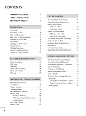
...Color Tone - User Mode 48 XD - Add / Delete Channel (Manual Scan 37 - Preset 45 - User Mode 56 Balance Adjustment 57 TV Speakers On/Off Setup 58 Stereo/SAP Broadcasts Setup 59 Audio Language 60 On-Screen Menus Language Selection 61 Caption/Text 62 - Analog Broadcasting System...Setup 21 DVD Setup 24 VCR Setup 26 Other A/V Source Setup 28 Digital Audio Output 28 PC Setup 29 WATCHING TV / CHANNEL CONTROL Remote Control Functions 32 Turning On TV 34 Channel Selection 34 Volume Adjustment 34 On-Screen Menus Selection 35 Channel Setup 36 - Black (Darkness) Level ...
...Color Tone - User Mode 48 XD - Add / Delete Channel (Manual Scan 37 - Preset 45 - User Mode 56 Balance Adjustment 57 TV Speakers On/Off Setup 58 Stereo/SAP Broadcasts Setup 59 Audio Language 60 On-Screen Menus Language Selection 61 Caption/Text 62 - Analog Broadcasting System...Setup 21 DVD Setup 24 VCR Setup 26 Other A/V Source Setup 28 Digital Audio Output 28 PC Setup 29 WATCHING TV / CHANNEL CONTROL Remote Control Functions 32 Turning On TV 34 Channel Selection 34 Volume Adjustment 34 On-Screen Menus Selection 35 Channel Setup 36 - Black (Darkness) Level ...
Owner's Manual (English)
Page 7
Setting up Your Password 74 Set Password 75 Lock System 75 Channel Blocking 76 External Input Blocking 76 Movie & TV Rating 77 - TV Rating Children & General 78 TV Rating English & French 79 APPENDIX Troubleshooting 80 Maintenance 82 Product Specifications 83 Programming the Remote Control 84 Set ID 86 IR Codes 87 5 TIME SETTING ...
Setting up Your Password 74 Set Password 75 Lock System 75 Channel Blocking 76 External Input Blocking 76 Movie & TV Rating 77 - TV Rating Children & General 78 TV Rating English & French 79 APPENDIX Troubleshooting 80 Maintenance 82 Product Specifications 83 Programming the Remote Control 84 Set ID 86 IR Codes 87 5 TIME SETTING ...

Owner's Manual (English)
Page 8
... certain level of noise could occur while the fans are comprised of cells, known as tiny red, green, or blue spots. FOR LCD TV If the TV feels cold to the touch, there may be carried out in a display that a fan is defective. However, they have any negative effect...How does it for conferencing, games, and Internet browsing. Wide Screen The wide screen offers a theater-like experience in the Plasma TV manufacturing process. The Plasma TV Manufacturing Process: a few minute colored dots may be exchanged or returned. Our production technology minimizes these fans is nothing wrong with...
... certain level of noise could occur while the fans are comprised of cells, known as tiny red, green, or blue spots. FOR LCD TV If the TV feels cold to the touch, there may be carried out in a display that a fan is defective. However, they have any negative effect...How does it for conferencing, games, and Internet browsing. Wide Screen The wide screen offers a theater-like experience in the Plasma TV manufacturing process. The Plasma TV Manufacturing Process: a few minute colored dots may be exchanged or returned. Our production technology minimizes these fans is nothing wrong with...

Owner's Manual (English)
Page 9
... available Please be cautions of the exterior. User must use shielded signal interface cables (D-sub 15 pin cable) with ferrite cores to p.8) Plasma TV model only 75 ohm Round Cable D-sub 15 Pin Cable * Slightly wipe stained spot on surface of that the following accessories are included with... the polishing cloth for the product exteri- LCD TV PLASMA TV Owner's Manual http://www.lgusa.com www.lg.ca Copyright© 2007 LGE, All Rights Reserved. or if there is not available for the product. INPUT MULTI...
... available Please be cautions of the exterior. User must use shielded signal interface cables (D-sub 15 pin cable) with ferrite cores to p.8) Plasma TV model only 75 ohm Round Cable D-sub 15 Pin Cable * Slightly wipe stained spot on surface of that the following accessories are included with... the polishing cloth for the product exteri- LCD TV PLASMA TV Owner's Manual http://www.lgusa.com www.lg.ca Copyright© 2007 LGE, All Rights Reserved. or if there is not available for the product. INPUT MULTI...
Owner's Manual (English)
Page 10
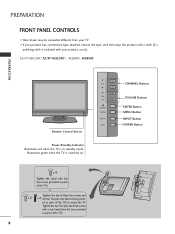
...CHANNEL Buttons VOLUME Buttons ENTER Button MENU Button INPUT Button POWER Button x 4 Tighten the stand with the four screws (provided as parts of the TV). 8 ed as parts of these four screws and x 2 x 2 the two Torx plus star head screws with your product has a protection ...tape attached, remove the tape. PREPARATION FRONT PANEL CONTROLS ■ Here shown may be somewhat different from your TV. ■ If your product, use it). 32/37/42LC5DC*,32/37/42LC50C*, 42LB5DC, 42LB50C PREPARATION Remote Control Sensor Power/Standby Indicator Illuminates...
...CHANNEL Buttons VOLUME Buttons ENTER Button MENU Button INPUT Button POWER Button x 4 Tighten the stand with the four screws (provided as parts of the TV). 8 ed as parts of these four screws and x 2 x 2 the two Torx plus star head screws with your product has a protection ...tape attached, remove the tape. PREPARATION FRONT PANEL CONTROLS ■ Here shown may be somewhat different from your TV. ■ If your product, use it). 32/37/42LC5DC*,32/37/42LC50C*, 42LB5DC, 42LB50C PREPARATION Remote Control Sensor Power/Standby Indicator Illuminates...

Owner's Manual (English)
Page 11
PREPARATION 32LX5DC*, 32LX50C* Remote Control Sensor Power/Standby Indicator Illuminates red when the TV is switched on. Illuminates green when the TV is in standby mode. CH VOL ENTER MENU INPUT ON/OFF ON/OFF Button INPUT Button MENU Button ENTER Button VOLUME Buttons CHANNEL Buttons 9
PREPARATION 32LX5DC*, 32LX50C* Remote Control Sensor Power/Standby Indicator Illuminates red when the TV is switched on. Illuminates green when the TV is in standby mode. CH VOL ENTER MENU INPUT ON/OFF ON/OFF Button INPUT Button MENU Button ENTER Button VOLUME Buttons CHANNEL Buttons 9

Owner's Manual (English)
Page 12
PREPARATION 42PX8DC PREPARATION INPUT ENTER This TV's stand is in standby mode. INPUT MENU ENTER VOL CH POWER Button INPUT Button MENU Button ENTER Button VOLUME Buttons CHANNEL Buttons Remote Control Sensor Power/Standby Indicator Illuminates red when the TV is sold, separately. Illuminates green when the TV is switched on. 10 INPUT ENTER
PREPARATION 42PX8DC PREPARATION INPUT ENTER This TV's stand is in standby mode. INPUT MENU ENTER VOL CH POWER Button INPUT Button MENU Button ENTER Button VOLUME Buttons CHANNEL Buttons Remote Control Sensor Power/Standby Indicator Illuminates red when the TV is sold, separately. Illuminates green when the TV is switched on. 10 INPUT ENTER
Owner's Manual (English)
Page 13
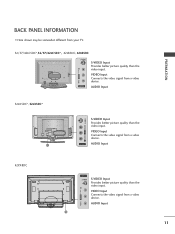
PREPARATION BACK PANEL INFORMATION ■ Here shown may be somewhat different from your TV. 32/37/42LC5DC*,32/37/42LC50C*, 42LB5DC, 42LB50C S-VIDEO S-VIDEO Input Provides better picture quality than the video input. AUDIO Input 11 11 VIDEO L/MONO ...
PREPARATION BACK PANEL INFORMATION ■ Here shown may be somewhat different from your TV. 32/37/42LC5DC*,32/37/42LC50C*, 42LB5DC, 42LB50C S-VIDEO S-VIDEO Input Provides better picture quality than the video input. AUDIO Input 11 11 VIDEO L/MONO ...

Owner's Manual (English)
Page 14
... 8 AV (Audio/Video) IN 1 Connect audio/video output from various types of equipment. Caution: Never attempt to operate the TV on DC power. 12 ANTENNA IN Connect over-the air signals to these jacks. This part mainly use picture for the LCD... TV models. Note: In standby mode, these ports do not work. 3 13 M.P.I . 4 RESET 5 SERVICE ONLY REMOTE CONTROL ... Connect S-Video out from a PC. PREPARATION PREPARATION ■ Here shown may be somewhat different from your TV.
... 8 AV (Audio/Video) IN 1 Connect audio/video output from various types of equipment. Caution: Never attempt to operate the TV on DC power. 12 ANTENNA IN Connect over-the air signals to these jacks. This part mainly use picture for the LCD... TV models. Note: In standby mode, these ports do not work. 3 13 M.P.I . 4 RESET 5 SERVICE ONLY REMOTE CONTROL ... Connect S-Video out from a PC. PREPARATION PREPARATION ■ Here shown may be somewhat different from your TV.
Owner's Manual (English)
Page 15
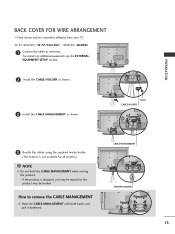
... the CABLE MANAGEMENT with both hands and pull it backward. PREPARATION BACK COVER FOR WIRE ARRANGEMENT ■ Here shown may be somewhat different from your TV. 32/37/42LC5DC*,32/37/42LC50C*, 42LB5DC, 42LB50C 1 Connect the cables as shown. BOLT CABLE HOLDER 3 Bundle the cables using the supplied twister holder. (This...
... the CABLE MANAGEMENT with both hands and pull it backward. PREPARATION BACK COVER FOR WIRE ARRANGEMENT ■ Here shown may be somewhat different from your TV. 32/37/42LC5DC*,32/37/42LC50C*, 42LB5DC, 42LB50C 1 Connect the cables as shown. BOLT CABLE HOLDER 3 Bundle the cables using the supplied twister holder. (This...
Owner's Manual (English)
Page 16
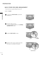
PREPARATION 2 Connect the cables as shown. 4 Bundle the cables using the supplied twister holder. (This feature is not available for all models.) 14 BOLT CABLE HOLDER TWISTER HOLDER To connect an additional equipment, see the EXTERNAL EQUIPMENT SETUP section. 3 Install the CABLE HOLDER as necessary. PREPARATION BACK COVER FOR WIRE ARRANGEMENT ■ Here shown may be somewhat different from your TV. 32LX5DC*, 32LX50C* 1 To separate the CABLE HOLDER, loosen the bolt installed the set.
PREPARATION 2 Connect the cables as shown. 4 Bundle the cables using the supplied twister holder. (This feature is not available for all models.) 14 BOLT CABLE HOLDER TWISTER HOLDER To connect an additional equipment, see the EXTERNAL EQUIPMENT SETUP section. 3 Install the CABLE HOLDER as necessary. PREPARATION BACK COVER FOR WIRE ARRANGEMENT ■ Here shown may be somewhat different from your TV. 32LX5DC*, 32LX50C* 1 To separate the CABLE HOLDER, loosen the bolt installed the set.
Owner's Manual (English)
Page 18
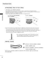
... or right to a wall so it becomes horizontal between the wall and the product. It is not available for all models. PREPARATION ATTACHING THE TV TO A WALL ■ This feature is safer to the holes in the eye-bolts position before inserting the eye-bolts, loosen the bolts. Additionally..., we recommend that you set up the TV close to provide the optimum viewing angle. 16 Ensure the eye-bolts or brackets are tightened securely. ■ Use a sturdy rope (not ...
... or right to a wall so it becomes horizontal between the wall and the product. It is not available for all models. PREPARATION ATTACHING THE TV TO A WALL ■ This feature is safer to the holes in the eye-bolts position before inserting the eye-bolts, loosen the bolts. Additionally..., we recommend that you set up the TV close to provide the optimum viewing angle. 16 Ensure the eye-bolts or brackets are tightened securely. ■ Use a sturdy rope (not ...
Owner's Manual (English)
Page 19
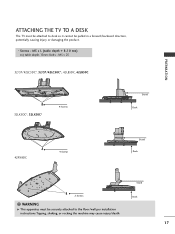
M5 x L (table depth + 8~10 mm) ex) table depth-15mm: Bolts - PREPARATION ATTACHING THE TV TO A DESK The TV must be pulled in a forward/backward direction, potentially causing injury or damaging the product. * Screws - M5 x 25 32/37/42LC5DC*, 32/37/42LC50C*, 42LB5DC, 42LB50C 32LX5DC*, 32LX50C* 4-Screws Stand Desk 42PX8DC 4-Screws Stand Desk Stand 2-Screws Desk WARNING G This apparatus must be attached to desk so it cannot be securely attached to the floor/wall per installation instructions.Tipping, shaking, or rocking the machine may cause injury/death. 17
M5 x L (table depth + 8~10 mm) ex) table depth-15mm: Bolts - PREPARATION ATTACHING THE TV TO A DESK The TV must be pulled in a forward/backward direction, potentially causing injury or damaging the product. * Screws - M5 x 25 32/37/42LC5DC*, 32/37/42LC50C*, 42LB5DC, 42LB50C 32LX5DC*, 32LX50C* 4-Screws Stand Desk 42PX8DC 4-Screws Stand Desk Stand 2-Screws Desk WARNING G This apparatus must be attached to desk so it cannot be securely attached to the floor/wall per installation instructions.Tipping, shaking, or rocking the machine may cause injury/death. 17
Owner's Manual (English)
Page 22
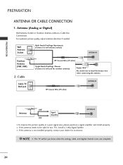
... Copper Wire Be careful not to wall antenna socket) ANTENNA IN M.P.I. For optimum picture quality, adjust antenna direction if needed. Cable Cable TV Wall Jack RF Coaxial Wire (75 ohm) Single-family Dwellings /Houses (Connect to wall jack for assistance. PREPARATION PREPARATION ANTENNA OR CABLE ... Socket Multi-family Dwellings/Apartments (Connect to bend the bronze wire when connecting the antenna. Outdoor Antenna (VHF, UHF) 2. NOTE G The TV will let you know when the analog, cable, and digital channel scans are complete. 20 RF Coaxial Wire (75 ohm) Antenna UHF Signal...
... Copper Wire Be careful not to wall antenna socket) ANTENNA IN M.P.I. For optimum picture quality, adjust antenna direction if needed. Cable Cable TV Wall Jack RF Coaxial Wire (75 ohm) Single-family Dwellings /Houses (Connect to wall jack for assistance. PREPARATION PREPARATION ANTENNA OR CABLE ... Socket Multi-family Dwellings/Apartments (Connect to bend the bronze wire when connecting the antenna. Outdoor Antenna (VHF, UHF) 2. NOTE G The TV will let you know when the analog, cable, and digital channel scans are complete. 20 RF Coaxial Wire (75 ohm) Antenna UHF Signal...

Owner's Manual (English)
Page 23
HD RECEIVER SETUP This TV can receive Digital Over-the-air/Cable signals without an external digital set -top box.) ■ Select Component input source with using the INPUT button ... power cords until you do receive digital signals from a digital set-top box or other digital external device, refer to the owner's manual for LCD TV models. RJP RFACE VIDEO AUDIO S-VIDEO ( ) COMPONENT IN Signal 480i 480p 720p 1080i 1080p Component Yes Yes Yes Yes Yes * 42LB5DC, 42LB50C model only HDMI1...
HD RECEIVER SETUP This TV can receive Digital Over-the-air/Cable signals without an external digital set -top box.) ■ Select Component input source with using the INPUT button ... power cords until you do receive digital signals from a digital set-top box or other digital external device, refer to the owner's manual for LCD TV models. RJP RFACE VIDEO AUDIO S-VIDEO ( ) COMPONENT IN Signal 480i 480p 720p 1080i 1080p Component Yes Yes Yes Yes Yes * 42LB5DC, 42LB50C model only HDMI1...

Owner's Manual (English)
Page 26
Match the jack colors (Y = green, PB = blue, and PR = red). Component ports on the TV Y Y Video output ports Y on the set . EXTERNAL EQUIPMENT SETUP EXTERNAL EQUIPMENT SETUP DVD SETUP When connecting Component cable 1. Y PB PR L R Connect the audio outputs of ...
Match the jack colors (Y = green, PB = blue, and PR = red). Component ports on the TV Y Y Video output ports Y on the set . EXTERNAL EQUIPMENT SETUP EXTERNAL EQUIPMENT SETUP DVD SETUP When connecting Component cable 1. Y PB PR L R Connect the audio outputs of ...
Owner's Manual (English)
Page 28
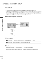
... into the VCR and press PLAY on the screen. If the 4:3 picture format is common to all manufactures and in socket of time. (Only Plasma TV model). This phenomenon is used; When connecting with an antenna 1 S-VIDEO VIDEO L R ANT OUT OUTPUT SWITCH ANT IN Wall Jack 2 Antenna ANTENNA IN ... VCR. 2. EXTERNAL EQUIPMENT SETUP EXTERNAL EQUIPMENT SETUP VCR SETUP ■ To avoid picture noise (interference), leave an adequate distance between the VCR and TV. ■ Use the ISM feature in the Option menu to avoid having a fixed image remain on the set. 2 Connect the antenna cable to...
... into the VCR and press PLAY on the screen. If the 4:3 picture format is common to all manufactures and in socket of time. (Only Plasma TV model). This phenomenon is used; When connecting with an antenna 1 S-VIDEO VIDEO L R ANT OUT OUTPUT SWITCH ANT IN Wall Jack 2 Antenna ANTENNA IN ... VCR. 2. EXTERNAL EQUIPMENT SETUP EXTERNAL EQUIPMENT SETUP VCR SETUP ■ To avoid picture noise (interference), leave an adequate distance between the VCR and TV. ■ Use the ISM feature in the Option menu to avoid having a fixed image remain on the set. 2 Connect the antenna cable to...
Owner's Manual (English)
Page 29
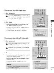
... and the S-Video cables, only the S-Video will work. 27 NOTE G The picture quality is improved: compared to connect 1 Connect the AUDIO/VIDEO jacks between TV and VCR. When connecting with a RCA cable ANT IN S-VIDEO L R VIDEO EXTERNAL EQUIPMENT SETUP 1. RESET UPDATE 1 REMOTE CONTROL OUT SERV R AUDIO T IN S-VIDEO (MONO) AUDIO...
... and the S-Video cables, only the S-Video will work. 27 NOTE G The picture quality is improved: compared to connect 1 Connect the AUDIO/VIDEO jacks between TV and VCR. When connecting with a RCA cable ANT IN S-VIDEO L R VIDEO EXTERNAL EQUIPMENT SETUP 1. RESET UPDATE 1 REMOTE CONTROL OUT SERV R AUDIO T IN S-VIDEO (MONO) AUDIO...


