User Manual
Page 5
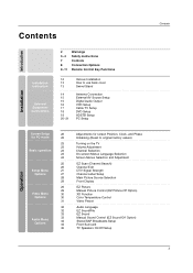
... Instructions Controls Connection Options Remote Control Key Functions 12 13 13 14 15 15 16 17 18 19 20~21 Various Installation How to use back cover Swivel Stand Antenna Connection External AV Source Setup Digital Audio Output VCR Setup Cable TV Setup DVD Setup HDSTB Setup PC Setup Installation ...Operation Screen Setup 22 for PC mode 22 23 23 Basic operation 23 23 24 25 26 Setup ...
... Instructions Controls Connection Options Remote Control Key Functions 12 13 13 14 15 15 16 17 18 19 20~21 Various Installation How to use back cover Swivel Stand Antenna Connection External AV Source Setup Digital Audio Output VCR Setup Cable TV Setup DVD Setup HDSTB Setup PC Setup Installation ...Operation Screen Setup 22 for PC mode 22 23 23 Basic operation 23 23 24 25 26 Setup ...
User Manual
Page 8
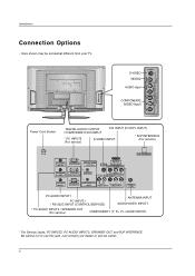
...INPUT (CONTROL/SERVICE) OUTPUT VIDEO1 COMPONENT1 PC AUDIO INPUT1 PC INPUT1 COMPONENT1/DVI R L INPUT AUDIO INPUT VIDEO INPUT Antenna PC AUDIO INPUT1 PC INPUT1 / RS-232C INPUT (CONTROL/SERVICE) ANTENNA INPUT AUDIO/VIDEO INPUT1 * PC AUDIO INPUT2 / SPEAKER OUT (For service...) COMPONENT1 (Y, PB, PR / AUDIO INPUT) * For Service Jacks: PC INPUT2, PC AUDIO INPUT2, SPEAKER OUT, and RJP INTERFACE Be careful not to use this jack. Introduction Connection...
...INPUT (CONTROL/SERVICE) OUTPUT VIDEO1 COMPONENT1 PC AUDIO INPUT1 PC INPUT1 COMPONENT1/DVI R L INPUT AUDIO INPUT VIDEO INPUT Antenna PC AUDIO INPUT1 PC INPUT1 / RS-232C INPUT (CONTROL/SERVICE) ANTENNA INPUT AUDIO/VIDEO INPUT1 * PC AUDIO INPUT2 / SPEAKER OUT (For service...) COMPONENT1 (Y, PB, PR / AUDIO INPUT) * For Service Jacks: PC INPUT2, PC AUDIO INPUT2, SPEAKER OUT, and RJP INTERFACE Be careful not to use this jack. Introduction Connection...
User Manual
Page 15
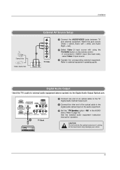
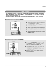
...RS-232C INPUT (CONTROL/SERVICE) OUTPUT VIDEO1 COMPONENT1 PC INPUT1 COMPONENT1/DVI R L INPUT AUDIO INPUT VIDEO INPUT 1/2 TV Back 1 Connect one end of an optical cable to the TV Digital Audio Optical Output port. 2 Connect the other end of the optical cable to ... Audio Output Optical port. Refer to VIDEO1 input (the back side), select Video 1 input source. 3 Operate the corresponding external equipment. If connected to external equipment operating guide. Installation Camcorder Video Game Set External AV Source Setup S-VIDEO VIDEO 2 R (MONO) L VIDEO AUDIO COMPONENT 2...
...RS-232C INPUT (CONTROL/SERVICE) OUTPUT VIDEO1 COMPONENT1 PC INPUT1 COMPONENT1/DVI R L INPUT AUDIO INPUT VIDEO INPUT 1/2 TV Back 1 Connect one end of an optical cable to the TV Digital Audio Optical Output port. 2 Connect the other end of the optical cable to ... Audio Output Optical port. Refer to VIDEO1 input (the back side), select Video 1 input source. 3 Operate the corresponding external equipment. If connected to external equipment operating guide. Installation Camcorder Video Game Set External AV Source Setup S-VIDEO VIDEO 2 R (MONO) L VIDEO AUDIO COMPONENT 2...
User Manual
Page 16
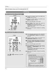
...red) 2 Insert a video tape into the VCR and press PLAY on the VCR. (Refer to the VCR owner's manual.) When connecting with a RCA cable TV Back DVI INPUT (PC/DTV INPUT) S-VIDEO R AUDIO L/MONO VIDEO VIDEO1 COMPONENT1 R L AUDIO INPUT VIDEO INPUT Antenna 1 ANT IN ANT OUT S-VIDEO ...OUT OUTPUT SWITCH (R) AUDIO (L) VIDEO 34 IN VCR 1 Connect the AUDIO/VIDEO jacks between the VCR and TV. - VCR Setup - When connecting with an antenna TV Back DVI INPUT (PC/DTV INPUT) S-VIDEO R AUDIO L/MONO VIDEO VIDEO1 COMPONENT1 R L AUDIO INPUT VIDEO INPUT Antenna...
...red) 2 Insert a video tape into the VCR and press PLAY on the VCR. (Refer to the VCR owner's manual.) When connecting with a RCA cable TV Back DVI INPUT (PC/DTV INPUT) S-VIDEO R AUDIO L/MONO VIDEO VIDEO1 COMPONENT1 R L AUDIO INPUT VIDEO INPUT Antenna 1 ANT IN ANT OUT S-VIDEO ...OUT OUTPUT SWITCH (R) AUDIO (L) VIDEO 34 IN VCR 1 Connect the AUDIO/VIDEO jacks between the VCR and TV. - VCR Setup - When connecting with an antenna TV Back DVI INPUT (PC/DTV INPUT) S-VIDEO R AUDIO L/MONO VIDEO VIDEO1 COMPONENT1 R L AUDIO INPUT VIDEO INPUT Antenna...
User Manual
Page 17
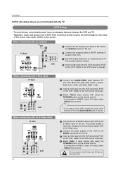
... same selected output channel on the remote control. - If connected to the RF antenna socket of the cable box. 3 Select 3 or 4 with the cable box remote control. When connecting with an antenna TV Back DVI INPUT (PC/DTV INPUT) S-VIDEO R AUDIO L/MONO VIDEO VIDEO1 COMPONENT1 ...R L AUDIO INPUT VIDEO INPUT Antenna 1/2 Cable Box (R) AUDIO (L) VIDEO TV VCR OUTPUT SWITCH 34 RF Cable 1 Connect the RF antenna socket of the cable...
... same selected output channel on the remote control. - If connected to the RF antenna socket of the cable box. 3 Select 3 or 4 with the cable box remote control. When connecting with an antenna TV Back DVI INPUT (PC/DTV INPUT) S-VIDEO R AUDIO L/MONO VIDEO VIDEO1 COMPONENT1 ...R L AUDIO INPUT VIDEO INPUT Antenna 1/2 Cable Box (R) AUDIO (L) VIDEO TV VCR OUTPUT SWITCH 34 RF Cable 1 Connect the RF antenna socket of the cable...
User Manual
Page 18
...8226; Digital Audio operation has priority if Digital Audio and AUDIO L/R are not included with the TV DVD Setup When connecting with a S-Video cable TV Back DVI INPUT (PC/DTV INPUT) S-VIDEO R AUDIO L/MONO VIDEO VIDEO1 COMPONENT1 R L AUDIO INPUT VIDEO INPUT Antenna 1 2 DVD S-VIDEO (R) AUDIO... (L) 1 Connect the S-VIDEO output of the DVD to the S-VIDEO input on the set. 2 Connect the audio outputs of the DVD to the...
...8226; Digital Audio operation has priority if Digital Audio and AUDIO L/R are not included with the TV DVD Setup When connecting with a S-Video cable TV Back DVI INPUT (PC/DTV INPUT) S-VIDEO R AUDIO L/MONO VIDEO VIDEO1 COMPONENT1 R L AUDIO INPUT VIDEO INPUT Antenna 1 2 DVD S-VIDEO (R) AUDIO... (L) 1 Connect the S-VIDEO output of the DVD to the S-VIDEO input on the set. 2 Connect the audio outputs of the DVD to the...
User Manual
Page 19
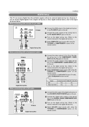
...Signal Component1/2 RGB-DTV, DVI-DTV 480i Yes No 480p/720p/1080i Yes Yes 1 Connect the DVI output of the digital set-top box to the DVI INPUT (PC/DTV INPUT) jack on the set. 2 Connect the digital audio outputs of the digital set-top box to the COMPONENT1 AUDIO INPUT ...on the digital set-top box. (Refer to the figure as shown below. When connecting with a D-sub 15 pin cable AC IN PC AUDIO INPUT2 PC INPUT2 DIGITAL AUDIO (OPTICAL) SPEAKER OUT RS-232C INPUT (CONTROL/SERVICE) OUTPUT PC AUDIO INPUT1 PC INPUT1 COMPONENT1/DVI INPUT TV Back 2 1 Digital Set-top Box (R) AUDIO (L) ...
...Signal Component1/2 RGB-DTV, DVI-DTV 480i Yes No 480p/720p/1080i Yes Yes 1 Connect the DVI output of the digital set-top box to the DVI INPUT (PC/DTV INPUT) jack on the set. 2 Connect the digital audio outputs of the digital set-top box to the COMPONENT1 AUDIO INPUT ...on the digital set-top box. (Refer to the figure as shown below. When connecting with a D-sub 15 pin cable AC IN PC AUDIO INPUT2 PC INPUT2 DIGITAL AUDIO (OPTICAL) SPEAKER OUT RS-232C INPUT (CONTROL/SERVICE) OUTPUT PC AUDIO INPUT1 PC INPUT1 COMPONENT1/DVI INPUT TV Back 2 1 Digital Set-top Box (R) AUDIO (L) ...
User Manual
Page 20
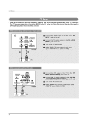
... OUTPUT VIDEO1 COMPONENT1 COMPONENT1/DVI R L INPUT AUDIO INPUT VIDEO INPUT Antenna 1 TV Back 2 DIGITAL AUDIO OPTICAL DVI-PC OUTPUT PC 1 Connect the DVI output of the PC to the DVI INPUT (PC/DTV INPUT) jack on the set. 2 Connect the PC audio outputs to the DIGITAL AUDIO COMPONENT1/DVI INPUT jack on the set. 3 Turn on the...
... OUTPUT VIDEO1 COMPONENT1 COMPONENT1/DVI R L INPUT AUDIO INPUT VIDEO INPUT Antenna 1 TV Back 2 DIGITAL AUDIO OPTICAL DVI-PC OUTPUT PC 1 Connect the DVI output of the PC to the DVI INPUT (PC/DTV INPUT) jack on the set. 2 Connect the PC audio outputs to the DIGITAL AUDIO COMPONENT1/DVI INPUT jack on the set. 3 Turn on the...
User Manual
Page 21
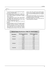
... fixed image on the TV's screen for Horizontal and Vertical frequencies is clear. To get the best picture quality, adjust the PC graphics card to another resolution, change the PC mode to another rate or adjust the brightness and contrast on your TV. If noise is set to display the... the graphic card on the TV. If the graphic card on the screen. 6. There may become permanently imprinted on the PC does not output analog and digital RGB simultaneously, connect only one of time. Check the image on the menu until the picture is separate. The synchronization input form for a...
... fixed image on the TV's screen for Horizontal and Vertical frequencies is clear. To get the best picture quality, adjust the PC graphics card to another resolution, change the PC mode to another rate or adjust the brightness and contrast on your TV. If noise is set to display the... the graphic card on the TV. If the graphic card on the screen. 6. There may become permanently imprinted on the PC does not output analog and digital RGB simultaneously, connect only one of time. Check the image on the menu until the picture is separate. The synchronization input form for a...
User Manual
Page 28
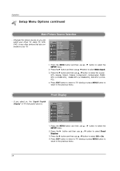
... SETUP menu. 2. Press the MENU button and then use D / E button to select the source: DTV, Analog, Video1, Video2, Component1, Component2, RGB1DTV (or RGB1-PC), RGB2-DTV (or RGB2-PC), DVI-DTV (or DVIPC). 4. Press the MENU button and then use D / E button to select Off or On. 4. Changes the picture source so you... return to TV viewing or press MENU button to return to your off-air TV, cable TV, VCR, DVD, or any other devices that are connected to the previous menu. Press the G button and then use D / E button to select the SETUP menu. 2.
... SETUP menu. 2. Press the MENU button and then use D / E button to select the source: DTV, Analog, Video1, Video2, Component1, Component2, RGB1DTV (or RGB1-PC), RGB2-DTV (or RGB2-PC), DVI-DTV (or DVIPC). 4. Press the MENU button and then use D / E button to select Off or On. 4. Changes the picture source so you... return to TV viewing or press MENU button to return to your off-air TV, cable TV, VCR, DVD, or any other devices that are connected to the previous menu. Press the G button and then use D / E button to select the SETUP menu. 2.
User Manual
Page 48
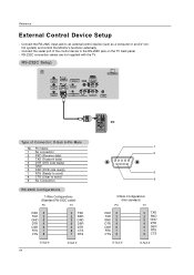
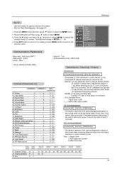
... Antenna Type of the control device to the RS-232C jack on the TV back panel. - Connect the RS-232C input jack to send) 9 No Connection RS-232C Configurations 7-Wire Configurations (Standard RS-232C cable) PC TV RXD 2 TXD 3 GND 5 DTR 4 DSR 6 RTS 7 CTS 8 3 TXD 2...6 DSR 4 DTR 8 CTS 7 RTS D-Sub 9 D-Sub 9 48 PC 1 5 9 6 3-Wire Configurations (Not standard) PC TV RXD 2 TXD 3 GND 5 DTR 4 DSR 6 RTS 7 CTS 8 3 TXD 2 RXD 5 GND 4 DTR 6 DSR 7 RTS 8 CTS D-Sub 9 D-Sub 9 D-Sub 9-Pin Male No. Connect the serial port of Connector; Reference External Control Device Setup - RS-232C...
... Antenna Type of the control device to the RS-232C jack on the TV back panel. - Connect the RS-232C input jack to send) 9 No Connection RS-232C Configurations 7-Wire Configurations (Standard RS-232C cable) PC TV RXD 2 TXD 3 GND 5 DTR 4 DSR 6 RTS 7 CTS 8 3 TXD 2...6 DSR 4 DTR 8 CTS 7 RTS D-Sub 9 D-Sub 9 48 PC 1 5 9 6 3-Wire Configurations (Not standard) PC TV RXD 2 TXD 3 GND 5 DTR 4 DSR 6 RTS 7 CTS 8 3 TXD 2 RXD 5 GND 4 DTR 6 DSR 7 RTS 8 CTS D-Sub 9 D-Sub 9 D-Sub 9-Pin Male No. Connect the serial port of Connector; Reference External Control Device Setup - RS-232C...
User Manual
Page 49
... Main Input 3. Screen Mute k 05. PIP/Double Wondow k 15. Color Temperature k 20. SETUP EZ Scan Ch.Edit 1. When selecting Set ID '0', every connected the TV is indicated as decimal (1~99) on menu and as Hexa decimal (0x0~0x63) on this time, if the data is data write mode..., it indicates present status data. If the data is data read status of the PC computer. Brightness k 09. Remote Control Lock Mode k 14. Use this format when receiving abnormal data from non-viable functions or communication errors. Contrast ...
... Main Input 3. Screen Mute k 05. PIP/Double Wondow k 15. Color Temperature k 20. SETUP EZ Scan Ch.Edit 1. When selecting Set ID '0', every connected the TV is indicated as decimal (1~99) on menu and as Hexa decimal (0x0~0x63) on this time, if the data is data write mode..., it indicates present status data. If the data is data read status of the PC computer. Brightness k 09. Remote Control Lock Mode k 14. Use this format when receiving abnormal data from non-viable functions or communication errors. Contrast ...


