
Owners Manual
Page 6
...13 14-18 Warnings TV Guide On Screen Notices / Digital Cable Compatibility Safety Instructions Accessories Controls (Model Name: 32/37/42LP1D) Connection Options (Model Name: 32/37/42LP1D) Controls (Model Name: 26/32LX1D. 26/32LX2D) Connection Options (Model Name: 26LX1D/2D) Connection Options (Model Name: 32LX1D/2D) Remote Control Key Functions 19 ...20 20 21 22-23 24-25 26-29 30 30 31 31 32-35 36-41 42-43 44-50 51-68 Various Installation How to use back cover Swivel...
...13 14-18 Warnings TV Guide On Screen Notices / Digital Cable Compatibility Safety Instructions Accessories Controls (Model Name: 32/37/42LP1D) Connection Options (Model Name: 32/37/42LP1D) Controls (Model Name: 26/32LX1D. 26/32LX2D) Connection Options (Model Name: 26LX1D/2D) Connection Options (Model Name: 32LX1D/2D) Remote Control Key Functions 19 ...20 20 21 22-23 24-25 26-29 30 30 31 31 32-35 36-41 42-43 44-50 51-68 Various Installation How to use back cover Swivel...
Owners Manual
Page 8
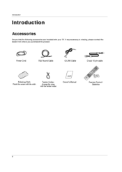
Introduction Introduction Accessories Ensure that the following accessories are included with the cloth. Power Cord 7552 Round Cable G-LINK Cable Polishing Cloth Polish the screen with your TV. Twister Holder Arrange the wires with the twister holder. If any accessory is missing, please contact the dealer from where you purchased the product. l=1 Owner's Manual D-sub 15 pin cable {03 1.0/) 1A1 Remote Control / Batteries 8
Introduction Introduction Accessories Ensure that the following accessories are included with the cloth. Power Cord 7552 Round Cable G-LINK Cable Polishing Cloth Polish the screen with your TV. Twister Holder Arrange the wires with the twister holder. If any accessory is missing, please contact the dealer from where you purchased the product. l=1 Owner's Manual D-sub 15 pin cable {03 1.0/) 1A1 Remote Control / Batteries 8
Owners Manual
Page 9
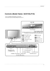
...441(Al Channel Display Power Standby Indicator Illuminates red when the TV is switched on, blinks green and then illuminates green. (lin/ DTV, CADTV mode 2 TV TV, CATV mode CIO Videol-2 mode Component) -2 mode Remote Control Sensor PC mode IJONfTOA Hi= HDMI mode MEM IEEE1394 0.4 ...Surround mode Xsruoio mode C f -G---EM= h4.O4(..vs,...re ,0 . ,100.19 V CH • VOL D. Introduction Controls (Model Name: 32/37/42LP1D) - When the TV is in...
...441(Al Channel Display Power Standby Indicator Illuminates red when the TV is switched on, blinks green and then illuminates green. (lin/ DTV, CADTV mode 2 TV TV, CATV mode CIO Videol-2 mode Component) -2 mode Remote Control Sensor PC mode IJONfTOA Hi= HDMI mode MEM IEEE1394 0.4 ...Surround mode Xsruoio mode C f -G---EM= h4.O4(..vs,...re ,0 . ,100.19 V CH • VOL D. Introduction Controls (Model Name: 32/37/42LP1D) - When the TV is in...
Owners Manual
Page 10
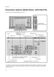
...INPUT / COMPONENT1 INPUT MONITOR OUT HDMI / IEEE1394 Port AUDIONIDEO INPUT1 CableCARD'" Slot HOMI a G-LINK DIGITAL AUDIO (OPTICAL) OUTPUT REMOTE CONTROL RS232C INPUT ICOVROUSERVICE) offElo DVI INPUT PC AUDIO INPUT RGB INPUT COMPONENT1 (PC/DTV INPUT) INPUT S-VIDE • COMPONENT1 AUDIO...CABLE nput REMOTE CONTROL Port COMPONENT1 (VIDEO / AUDIO INPUT) * The HDMI port can receive video via High-Definition Multimedia Interface (HDMI) or the Digital Visual Interface (DV!). Here shown may be somewhat different from your TV. Introduction Connection Options (Model Name: 32/37/42LP1D)...
...INPUT / COMPONENT1 INPUT MONITOR OUT HDMI / IEEE1394 Port AUDIONIDEO INPUT1 CableCARD'" Slot HOMI a G-LINK DIGITAL AUDIO (OPTICAL) OUTPUT REMOTE CONTROL RS232C INPUT ICOVROUSERVICE) offElo DVI INPUT PC AUDIO INPUT RGB INPUT COMPONENT1 (PC/DTV INPUT) INPUT S-VIDE • COMPONENT1 AUDIO...CABLE nput REMOTE CONTROL Port COMPONENT1 (VIDEO / AUDIO INPUT) * The HDMI port can receive video via High-Definition Multimedia Interface (HDMI) or the Digital Visual Interface (DV!). Here shown may be somewhat different from your TV. Introduction Connection Options (Model Name: 32/37/42LP1D)...
Owners Manual
Page 11
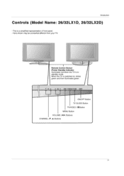
Remote Control Sensor /Power Standby Indicator Illuminates red when the TV is switched on, blinks green and then illuminates green. ♦ CH ♦ Al V0L ► MENU 'VVIDEO,'0.) TV &ADE °HOFF ON/OFF Button TV GUIDE Button TVNIDEO /®Button MENU Button VOLUME (4,►) Buttons CHANNEL (V, ♦) Buttons 11 Introduction Controls (Model Name: 26/32LX1D, 26/32LX2D) - Here shown may be somewhat different from your TV. When the TV is in standby mode. This is a simplified representation of front panel. -
Remote Control Sensor /Power Standby Indicator Illuminates red when the TV is switched on, blinks green and then illuminates green. ♦ CH ♦ Al V0L ► MENU 'VVIDEO,'0.) TV &ADE °HOFF ON/OFF Button TV GUIDE Button TVNIDEO /®Button MENU Button VOLUME (4,►) Buttons CHANNEL (V, ♦) Buttons 11 Introduction Controls (Model Name: 26/32LX1D, 26/32LX2D) - Here shown may be somewhat different from your TV. When the TV is in standby mode. This is a simplified representation of front panel. -
Owners Manual
Page 12
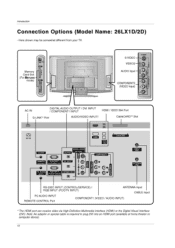
...stores). 12 Here shown may be somewhat different from your TV. CABLE Niso or, ANTENNA (MO) PC AUDIO RGB INPUT C0MP0NENT1INPUT INPUT (PC/DTV INPUT) G RS-232C INPUT (CONTROL/SERVICE) / RGB INPUT (PC/DTV INPUT) ANTENNA Input CABLE Input PC AUDIO INPUT REMOTE CONTROL Port COMPONENT1 (VIDEO / AUDIO INPUT) * The HDMI ...) 0 AC IN DIGITAL AUDIO OUTPUT / DVI INPUT / COMPONENT1 INPUT HDMI / IEEE1394 Port G-LINKm Port AUDIONIDEO INPUT1 CableCARD"' Slot !MI 1 GrLINK OUTPUT 06590 REMOTE RS•232C INPUT 0 CO ROL {CONTIVABIVICEPORT) L_J El HOMI u IEEE 13,114 izazzaa-
...stores). 12 Here shown may be somewhat different from your TV. CABLE Niso or, ANTENNA (MO) PC AUDIO RGB INPUT C0MP0NENT1INPUT INPUT (PC/DTV INPUT) G RS-232C INPUT (CONTROL/SERVICE) / RGB INPUT (PC/DTV INPUT) ANTENNA Input CABLE Input PC AUDIO INPUT REMOTE CONTROL Port COMPONENT1 (VIDEO / AUDIO INPUT) * The HDMI ...) 0 AC IN DIGITAL AUDIO OUTPUT / DVI INPUT / COMPONENT1 INPUT HDMI / IEEE1394 Port G-LINKm Port AUDIONIDEO INPUT1 CableCARD"' Slot !MI 1 GrLINK OUTPUT 06590 REMOTE RS•232C INPUT 0 CO ROL {CONTIVABIVICEPORT) L_J El HOMI u IEEE 13,114 izazzaa-
Owners Manual
Page 13
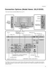
... Port AUDIONIDEO INPUT1 I CableCARD'" Slot IMP l l / 8• AC IN HDMI • CabloCARD G-LINK DIGITAL AUDIO (OPTICAL) OUTPUT REMOTE CONTROL PC AUDIO INPUT RS•232C INPUT ICONTR0USERVICE) - Here shown may be somewhat different from your TV. S-VIDE Gi CI) IEEE 1394 MONITOR OUT VIDEO 1 CABLE (MO) COMPONENT1 00 0 0 0 4_9 9 9 AUDIO INPUT VIDEO INPUT...
... Port AUDIONIDEO INPUT1 I CableCARD'" Slot IMP l l / 8• AC IN HDMI • CabloCARD G-LINK DIGITAL AUDIO (OPTICAL) OUTPUT REMOTE CONTROL PC AUDIO INPUT RS•232C INPUT ICONTR0USERVICE) - Here shown may be somewhat different from your TV. S-VIDE Gi CI) IEEE 1394 MONITOR OUT VIDEO 1 CABLE (MO) COMPONENT1 00 0 0 0 4_9 9 9 AUDIO INPUT VIDEO INPUT...
Owners Manual
Page 14
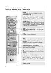
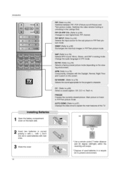
...TIMER RATIO ADJUST SWAP 00 00 SAP ES F1C AF'M EZ SOUND 00 00 CC FREEZE AUTO DEMO MC EJECT 00 00 TV GUIDE LIGHT Illuminates the remote control buttons. In Videol-2, Component 1-2, RGB-DTV (or RGB-PC), HDMVDVI, and IEEE1394 input sources, screen returns to the ...or RGB-PC), HDMI/DVI). (Video 1-2, Component 1-2 input sources are linked automatically, Only if these are connected) MODE Selects the remote operating mode: TV, VCR, DVD, CABLE, STB or AUDIO. Introduction Remote Control Key Functions NPU r iv AUDIO ■ POWER ( 1 CVO MODE - r XI T 1394 MARK 000° • PAGE ...
...TIMER RATIO ADJUST SWAP 00 00 SAP ES F1C AF'M EZ SOUND 00 00 CC FREEZE AUTO DEMO MC EJECT 00 00 TV GUIDE LIGHT Illuminates the remote control buttons. In Videol-2, Component 1-2, RGB-DTV (or RGB-PC), HDMVDVI, and IEEE1394 input sources, screen returns to the ...or RGB-PC), HDMI/DVI). (Video 1-2, Component 1-2 input sources are linked automatically, Only if these are connected) MODE Selects the remote operating mode: TV, VCR, DVD, CABLE, STB or AUDIO. Introduction Remote Control Key Functions NPU r iv AUDIO ■ POWER ( 1 CVO MODE - r XI T 1394 MARK 000° • PAGE ...
Owners Manual
Page 16
...to p.86) Select a closed caption: Off, CC1-4, Text1-4. APM (Refer to prevent environment. ass * Use a remote control 7 meter distance and 30 degree (left/right) within the receiving unit scope. * Dispose of this TV. i.e 4 ;P . PIP PIP INPUT O 0 00 I IMER RATIO ADJUST SWAP O 00 O SAP EZ PIG... APM EZ SOUND I00 00 CC FrIrl,7r AuToormo MCijroo )) ) ) TV GUIDE Installing Batteries I Open the battery compartment I , 2 3 4 5 6 7 8 9 - 0 FLASHI3KI PIP PIP CH- SWAP (Refer to p.94) Selects the...
...to p.86) Select a closed caption: Off, CC1-4, Text1-4. APM (Refer to prevent environment. ass * Use a remote control 7 meter distance and 30 degree (left/right) within the receiving unit scope. * Dispose of this TV. i.e 4 ;P . PIP PIP INPUT O 0 00 I IMER RATIO ADJUST SWAP O 00 O SAP EZ PIG... APM EZ SOUND I00 00 CC FrIrl,7r AuToormo MCijroo )) ) ) TV GUIDE Installing Batteries I Open the battery compartment I , 2 3 4 5 6 7 8 9 - 0 FLASHI3KI PIP PIP CH- SWAP (Refer to p.94) Selects the...
Owners Manual
Page 22
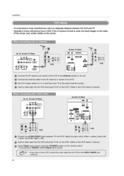
...tape into the VCR and press PLAY on the remote control. - If connected to VIDEO2, select Video2 input source. 0, • If you have a mono VCR, connect the audio cable from a VCR. To avoid picture noise (interference), leave an adequate distance between TV and VCR. Installation - MI OM ®o...ir .9 o 6,0•60.1. 0 .00, VCR • Connect the AUDIONIDEO jacks between the VCR and TV. - the fixed images on the screen. When connecting with a RCA cable 32, 37, 42 inch TV Back • O IAOMTOR OUT 4040( IDE01 r- If the 4:3 picture format is used; Typically a ...
...tape into the VCR and press PLAY on the remote control. - If connected to VIDEO2, select Video2 input source. 0, • If you have a mono VCR, connect the audio cable from a VCR. To avoid picture noise (interference), leave an adequate distance between TV and VCR. Installation - MI OM ®o...ir .9 o 6,0•60.1. 0 .00, VCR • Connect the AUDIONIDEO jacks between the VCR and TV. - the fixed images on the screen. When connecting with a RCA cable 32, 37, 42 inch TV Back • O IAOMTOR OUT 4040( IDE01 r- If the 4:3 picture format is used; Typically a ...
Owners Manual
Page 23
... button on the set . • Insert a video tape into the VCR and press PLAY on the VCR. (Refer to the S-VIDEO input on the remote control. - NPUT 26 Inch TV Back • *CS AMT • ° II ., ANTON LVIp0 0O4 W V s'IT o 'I0 .0$00.1 V.0 VCR e • • vloro e• a 'a . ...input. • Connect the audio outputs of the VCR to the VCR owner's manual.) O Select Videol input source with an S-Video cable 32, 37, 42 Inch TV Back e SVCE0 04".V4IMONITOR 7. The picture quality is improved; W VCR • Connect the S-VIDEO output of the VCR to the ...
... button on the set . • Insert a video tape into the VCR and press PLAY on the VCR. (Refer to the S-VIDEO input on the remote control. - NPUT 26 Inch TV Back • *CS AMT • ° II ., ANTON LVIp0 0O4 W V s'IT o 'I0 .0$00.1 V.0 VCR e • • vloro e• a 'a . ...input. • Connect the audio outputs of the VCR to the VCR owner's manual.) O Select Videol input source with an S-Video cable 32, 37, 42 Inch TV Back e SVCE0 04".V4IMONITOR 7. The picture quality is improved; W VCR • Connect the S-VIDEO output of the VCR to the ...

Owners Manual
Page 24
... HDMI input source with using the TVNIDEO button on the remote control. • Refer to the DVD player's manual for operating instructions. Installation DVD Setup When connecting with a S-Video cable 32S,VO37I,CD4E2-O6EI)n-IcIAOh1TIUV"VBO°DaItcUDiIkfCfTE°O"OP1O AUDIVOIDiPEUT 26 inch TV Back ow LI • ■ O DVD PSV.INIAO/)UP4DIO fa...
... HDMI input source with using the TVNIDEO button on the remote control. • Refer to the DVD player's manual for operating instructions. Installation DVD Setup When connecting with a S-Video cable 32S,VO37I,CD4E2-O6EI)n-IcIAOh1TIUV"VBO°DaItcUDiIkfCfTE°O"OP1O AUDIVOIDiPEUT 26 inch TV Back ow LI • ■ O DVD PSV.INIAO/)UP4DIO fa...
Owners Manual
Page 25
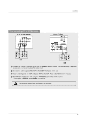
... audio output of the DVD to the DIGITAL AUDIO COMPONENT1 INPUT jack on the set . O Select Component 1 input source with a component cable 32, 37, 42 inch TV Back DIGITAL AUDIO1...._ {OPTICAL) 'OUTPUT I =D - 0 COPPOUMRVICE rt.V11 INPUT 0 ,40000:o GVIDEO O MONITOR OUT VIDEOI COIAPONENT1 ROB IIIPNT ... Il) P., DVD ts, Select Gpor depending on your DVD connector. Component ports on the TV Y Ps PR Video output ports on the DVD player, insert a DVD. Installation When connecting with using the TVNIDEO button on the remote control. - O Turn on DVD player Y Pb Pr Y B-Y R-Y Y Cb Cr Y...
... audio output of the DVD to the DIGITAL AUDIO COMPONENT1 INPUT jack on the set . O Select Component 1 input source with a component cable 32, 37, 42 inch TV Back DIGITAL AUDIO1...._ {OPTICAL) 'OUTPUT I =D - 0 COPPOUMRVICE rt.V11 INPUT 0 ,40000:o GVIDEO O MONITOR OUT VIDEOI COIAPONENT1 ROB IIIPNT ... Il) P., DVD ts, Select Gpor depending on your DVD connector. Component ports on the TV Y Ps PR Video output ports on the DVD player, insert a DVD. Installation When connecting with using the TVNIDEO button on the remote control. - O Turn on DVD player Y Pb Pr Y B-Y R-Y Y Cb Cr Y...
Owners Manual
Page 26
Installation ID naLl a ,! - O Turn on the digital set-top box. (Refer to the PC AUDIO INPUT jack on the remote control. 26 This TV can receive Digital Over-the-air/Cable signals without an external digital set . However, if you do receive Digital signals from a digital set-top box ...or other digital external device, refer to the figure as shown below. 32, 37, 42 inch TV Back AC IN DIGITAL AUDIO (OPTICAL) cli=1) 'OUTP▪ UTI bVi INPUT PC AUDIO INPUT PCN1TV I CO/IPONENTI INPUT 26 inch...
Installation ID naLl a ,! - O Turn on the digital set-top box. (Refer to the PC AUDIO INPUT jack on the remote control. 26 This TV can receive Digital Over-the-air/Cable signals without an external digital set . However, if you do receive Digital signals from a digital set-top box ...or other digital external device, refer to the figure as shown below. 32, 37, 42 inch TV Back AC IN DIGITAL AUDIO (OPTICAL) cli=1) 'OUTP▪ UTI bVi INPUT PC AUDIO INPUT PCN1TV I CO/IPONENTI INPUT 26 inch...
Owners Manual
Page 27
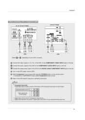
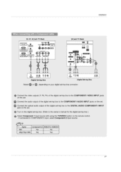
... the TVNIDEO button on the remote control. - T.. .. If connected to the owner's manual for the digital set . Connect the audio output of the digital set-top box to the COMPONENT1 AUDIO INPUT jacks on the set -top box.) O Select Component 1 input source with a Component cable 32, 37, 42 inch TV Back DIGITAL AUDIO (OPTIGAL1.../720p/1080i Yes Yes 27 MO0•1M11M1•1AO el 0 C) MI) AMMO It) II Po Po Digital Set-top Box .ook- Si 26 inch TV Back tem Li 0 ILL CI RBI MAID W.
... the TVNIDEO button on the remote control. - T.. .. If connected to the owner's manual for the digital set . Connect the audio output of the digital set-top box to the COMPONENT1 AUDIO INPUT jacks on the set -top box.) O Select Component 1 input source with a Component cable 32, 37, 42 inch TV Back DIGITAL AUDIO (OPTIGAL1.../720p/1080i Yes Yes 27 MO0•1M11M1•1AO el 0 C) MI) AMMO It) II Po Po Digital Set-top Box .ook- Si 26 inch TV Back tem Li 0 ILL CI RBI MAID W.
Owners Manual
Page 28
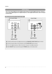
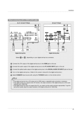
O Select HDMI/DVI input source with a HDMI cable 32, 37, 42 inch TV Back O i* umcum WEE 26 inch TV Back " ECM m' ic=i3a CM] 0 Co MOCKEITV OUTPUT Digital Set-top Box UPIO•OTY OVTINT Digital Set-lop Box &#...8226; Connect the HDMI output of the digital set-top box to the owner's manual for the digital set-top box.) • TV can receive the video and audio signal simultaneously with using the TVNIDEO button on the set. To get the best picture quality, adjust ...digital set-top box will be auto- O Turn on the digital set-top box. (Refer to the HDMI jack on the remote control.
O Select HDMI/DVI input source with a HDMI cable 32, 37, 42 inch TV Back O i* umcum WEE 26 inch TV Back " ECM m' ic=i3a CM] 0 Co MOCKEITV OUTPUT Digital Set-top Box UPIO•OTY OVTINT Digital Set-lop Box &#...8226; Connect the HDMI output of the digital set-top box to the owner's manual for the digital set-top box.) • TV can receive the video and audio signal simultaneously with using the TVNIDEO button on the set. To get the best picture quality, adjust ...digital set-top box will be auto- O Turn on the digital set-top box. (Refer to the HDMI jack on the remote control.
Owners Manual
Page 29
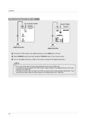
... NWT 4__9 c c≥9 0, 0 INPUT VIOCO INPUT 26 inch TV Back • 1, 11,O C P01 0 I - 3 C- OE I = 0 Wel 0 MSS j5 MOM 4c- fa Connect the audio output of the digital set-top box to the PC AUDIO INPUT jack on the remote control. • If the digital set-top box has a DVI output... set -top box to the owner's manual for the digital set-top box.) • Select HDMI/DVI input source with a HDMI to DVI cable 32, 37, 42 inch TV Back H OPUTPOOPPIT • • I G.UNK I DIGITAL AUDIO (OPTICAL I .A rr . 'MOW MIMI Digital Set-top Box Digital Set-top Box OVIOTV 01FITIO...
... NWT 4__9 c c≥9 0, 0 INPUT VIOCO INPUT 26 inch TV Back • 1, 11,O C P01 0 I - 3 C- OE I = 0 Wel 0 MSS j5 MOM 4c- fa Connect the audio output of the digital set-top box to the PC AUDIO INPUT jack on the remote control. • If the digital set-top box has a DVI output... set -top box to the owner's manual for the digital set-top box.) • Select HDMI/DVI input source with a HDMI to DVI cable 32, 37, 42 inch TV Back H OPUTPOOPPIT • • I G.UNK I DIGITAL AUDIO (OPTICAL I .A rr . 'MOW MIMI Digital Set-top Box Digital Set-top Box OVIOTV 01FITIO...

Owners Manual
Page 30
... the AUDIONIDEO jacks between TV and external equipment. DVI INPUT - O See the external audio equipment instruction manual for operation. Refer to the digital audio optical input on the remote control. - O Connect the other end of an optical cable to VIDEO1 input, select Videol input source. • ...may damage your vision. 30 For connection instructions to external audio equipment (stereo system) via the Digital Audio Output Optical port. 32, 37, 42 inch TV Back 26 inch TV Back tEti AC IN 0 MEM 0 0 PC AUDIO INPUT DIGITAL AUDIO (OPTICAL) 41=10 lan120 - O Select Video2 ...
... the AUDIONIDEO jacks between TV and external equipment. DVI INPUT - O See the external audio equipment instruction manual for operation. Refer to the digital audio optical input on the remote control. - O Connect the other end of an optical cable to VIDEO1 input, select Videol input source. • ...may damage your vision. 30 For connection instructions to external audio equipment (stereo system) via the Digital Audio Output Optical port. 32, 37, 42 inch TV Back 26 inch TV Back tEti AC IN 0 MEM 0 0 PC AUDIO INPUT DIGITAL AUDIO (OPTICAL) 41=10 lan120 - O Select Video2 ...
Owners Manual
Page 32
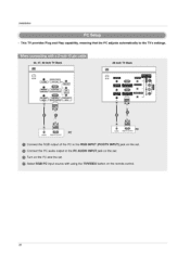
... the PC adjusts automatically to the PC AUDIO INPUT jack on the remote control. 32 When connecting with using the TVNIDEO button on the set. O Select RGB-PC input source with a D-sub 15 pin cable 32, 37,;42 Inch TV Back 26 inch TV Back AC IN 0 DIGITAL AUDIO G-LINK I (OPTICAL) c171) OUTP▪ UT a PC... output of the PC to the RGB INPUT (PC/DTV INPUT) jack on the PC and the set . O Connect the PC audio output to the TV's settings.
... the PC adjusts automatically to the PC AUDIO INPUT jack on the remote control. 32 When connecting with using the TVNIDEO button on the set. O Select RGB-PC input source with a D-sub 15 pin cable 32, 37,;42 Inch TV Back 26 inch TV Back AC IN 0 DIGITAL AUDIO G-LINK I (OPTICAL) c171) OUTP▪ UT a PC... output of the PC to the RGB INPUT (PC/DTV INPUT) jack on the PC and the set . O Connect the PC audio output to the TV's settings.
Owners Manual
Page 33
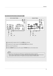
Installation When connecting with a HDMI to DVI cable 32, 37, 42 inch TV Back : WSW [ I D 26 inch TV Back 3941 0 04.INK DIGITAL AUDIO {0, TICAL) Es iOV1Ptril 9.000.10 • • 410.
Installation When connecting with a HDMI to DVI cable 32, 37, 42 inch TV Back : WSW [ I D 26 inch TV Back 3941 0 04.INK DIGITAL AUDIO {0, TICAL) Es iOV1Ptril 9.000.10 • • 410.

