Owners Manual
Page 2
... equipment and receiver. - Any changes or modifications not expressly approved by one or more of important operating and maintenance (servicing) instructions in particular, specifies that to radio or television reception, which can radiate radio frequency energy and, if not installed and used in any way without written authorization from that the cable ground shall be determined by turning the equipment...
... equipment and receiver. - Any changes or modifications not expressly approved by one or more of important operating and maintenance (servicing) instructions in particular, specifies that to radio or television reception, which can radiate radio frequency energy and, if not installed and used in any way without written authorization from that the cable ground shall be determined by turning the equipment...
Owners Manual
Page 5
... Ventilation Install your TV where there is turned off, unplugged and all cables have been removed. Antenna grounding according to the National Electrical Code, ANSI/NFPA 70 Ground Clamp Electric Service Equipment NEC: National Electrical Code Antenna Lead in Wire Antenna Discharge Unit (NEC Section 810-20) Grounding Conductors (NEC Section 810-21) Ground Clamps Power Service Grounding Electrode System (NEC Art 250, Part...
... Ventilation Install your TV where there is turned off, unplugged and all cables have been removed. Antenna grounding according to the National Electrical Code, ANSI/NFPA 70 Ground Clamp Electric Service Equipment NEC: National Electrical Code Antenna Lead in Wire Antenna Discharge Unit (NEC Section 810-20) Grounding Conductors (NEC Section 810-21) Ground Clamps Power Service Grounding Electrode System (NEC Art 250, Part...
Owners Manual
Page 6
...) Mode only 70 Manual Configure 71 Selecting XGA Mode 72 Initializing (Reset to a Desk 18 VESA Wall Mounting 19 Desktop Pedestal Installation 19 Antenna or Cable Connection 20 EXTERNAL EQUIPMENT SETUP HD Receiver Setup 21 DVD Setup 24 VCR Setup 26 Other A/V Source Setup 28 Digital Audio Output 28 PC Setup 29 WATCHING TV / CHANNEL CONTROL Remote Control Functions 32 Turning On TV 34 Channel Selection 34 Volume Adjustment 34 On-Screen Menus Selection 35 Channel Setup 36 - Preset 45 - EZ Picture - User Mode 48 XD - Auto Scan (EZ Scan 36 - Channel Editing 38 DTV Signal...
...) Mode only 70 Manual Configure 71 Selecting XGA Mode 72 Initializing (Reset to a Desk 18 VESA Wall Mounting 19 Desktop Pedestal Installation 19 Antenna or Cable Connection 20 EXTERNAL EQUIPMENT SETUP HD Receiver Setup 21 DVD Setup 24 VCR Setup 26 Other A/V Source Setup 28 Digital Audio Output 28 PC Setup 29 WATCHING TV / CHANNEL CONTROL Remote Control Functions 32 Turning On TV 34 Channel Selection 34 Volume Adjustment 34 On-Screen Menus Selection 35 Channel Setup 36 - Preset 45 - EZ Picture - User Mode 48 XD - Auto Scan (EZ Scan 36 - Channel Editing 38 DTV Signal...
Owners Manual
Page 11
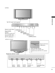
...POWER Button INPUT Button MENU Button ENTER Button VOLUME Buttons CHANNEL Buttons 42PG60C, 42PG65C Stand (Only 42PG65C model) Remote Control Sensor POWER Button Power/Standby Indicator Illuminates red in standby mode. INPUT ENTER Illuminates blue when the set is sold, separately. 42PX8DC PREPARATION INPUT ENTER This TV's stand is switched on . INPUT MENU ENTER VOL CH INPUT MENU ENTER VOL CH INPUT MENU ENTER VOL CH INPUT Button MENU Button ENTER Button VOLUME (-,+) Buttons CHANNEL (E, D) Buttons 9 Illuminates green when the TV is in standby mode. INPUT...
...POWER Button INPUT Button MENU Button ENTER Button VOLUME Buttons CHANNEL Buttons 42PG60C, 42PG65C Stand (Only 42PG65C model) Remote Control Sensor POWER Button Power/Standby Indicator Illuminates red in standby mode. INPUT ENTER Illuminates blue when the set is sold, separately. 42PX8DC PREPARATION INPUT ENTER This TV's stand is switched on . INPUT MENU ENTER VOL CH INPUT MENU ENTER VOL CH INPUT MENU ENTER VOL CH INPUT Button MENU Button ENTER Button VOLUME (-,+) Buttons CHANNEL (E, D) Buttons 9 Illuminates green when the TV is in standby mode. INPUT...
Owners Manual
Page 13
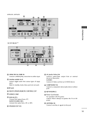
S-VIDEO Connect S-Video out from an S-VIDEO device. 9 COMPONENT IN Connect a component video/audio device to this jack. 11 Note: In standby mode, these ports do not work. 3 13 M.P.I 4 RESET/UPDATE/REMOTE CONTROL OUT 5 SERVICE ONLY 6 RGB IN (PC) Connect the output from various types of equipment. Caution: Never attempt to operate the TV on DC power. 12 ANTENNA IN Connect over-the air signals to these jacks. 10 RJP INTERFACE 11 Power Cord Socket For operation with AC power. PREPARATION 42PG60C...
S-VIDEO Connect S-Video out from an S-VIDEO device. 9 COMPONENT IN Connect a component video/audio device to this jack. 11 Note: In standby mode, these ports do not work. 3 13 M.P.I 4 RESET/UPDATE/REMOTE CONTROL OUT 5 SERVICE ONLY 6 RGB IN (PC) Connect the output from various types of equipment. Caution: Never attempt to operate the TV on DC power. 12 ANTENNA IN Connect over-the air signals to these jacks. 10 RJP INTERFACE 11 Power Cord Socket For operation with AC power. PREPARATION 42PG60C...
Owners Manual
Page 21
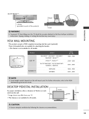
... the VESA Wall Mounting Instruction Guide. A B Product LCD TV PLASMA TV Model 32LC5DC*, 32LC50C*, 32LX5DC*, 32LX50C*, 32LG5*** 37LG5***, 42LG5*** 32/37/42LC5DC*, 32/37/42LC50C*, 42LB5DC, 42LB50C 42PG60C 42PX8DC VESA (A * B) 200 * 100 200 * 200 600 * 400 400 * 400 600 * 400 NOTE G Screw length needed depends on each side from your TV. ■ This feature is not available for all models. 32/37/42LG5*** Stand PREPARATION 1-Screw (provided as parts of...
... the VESA Wall Mounting Instruction Guide. A B Product LCD TV PLASMA TV Model 32LC5DC*, 32LC50C*, 32LX5DC*, 32LX50C*, 32LG5*** 37LG5***, 42LG5*** 32/37/42LC5DC*, 32/37/42LC50C*, 42LB5DC, 42LB50C 42PG60C 42PX8DC VESA (A * B) 200 * 100 200 * 200 600 * 400 400 * 400 600 * 400 NOTE G Screw length needed depends on each side from your TV. ■ This feature is not available for all models. 32/37/42LG5*** Stand PREPARATION 1-Screw (provided as parts of...
Owners Manual
Page 23
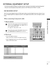
... Component input source with using the INPUT button on the remote control. Match the jack colors (Y = green, PB = blue, and PR = red). Y PB PR L R Connect the audio output of the digital set top box to the COMPONENT IN VIDEO jacks on the digital set-top box. (Refer to the owner's manual for LCD TV(Except 32/37/42LG5***) models. EXTERNAL EQUIPMENT SETUP EXTERNAL EQUIPMENT SETUP ■ To prevent the equipment damage, never plug in any power cords until you do receive digital signals from a digital set-top box or other digital external device...
... Component input source with using the INPUT button on the remote control. Match the jack colors (Y = green, PB = blue, and PR = red). Y PB PR L R Connect the audio output of the digital set top box to the COMPONENT IN VIDEO jacks on the digital set-top box. (Refer to the owner's manual for LCD TV(Except 32/37/42LG5***) models. EXTERNAL EQUIPMENT SETUP EXTERNAL EQUIPMENT SETUP ■ To prevent the equipment damage, never plug in any power cords until you do receive digital signals from a digital set-top box or other digital external device...
Owners Manual
Page 24
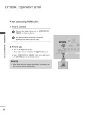
... not support Auto HDMI, you need to the owner's manual for the digital set-top box.) ■ Select HDMI1/DVI or HDMI2 input source with using the INPUT button on the remote control. HDMI/DVI IN 1(DVI) DIGITAL AUDIO OUT (OPTICAL) 2 M.P.I RJP INTERFACE 1 VIDEO AUDIO COMPONENT IN HDMI-DTV OUTPUT ( ) 22 How to use ■ Turn on the set the output resolution appropriately. How to connect 1 Connect the digital set-top box to HDMI/DVI IN 1(DVI) or 2 jack on the digital set-top box. ( ) (Refer to set . 2 No separated audio connection...
... not support Auto HDMI, you need to the owner's manual for the digital set-top box.) ■ Select HDMI1/DVI or HDMI2 input source with using the INPUT button on the remote control. HDMI/DVI IN 1(DVI) DIGITAL AUDIO OUT (OPTICAL) 2 M.P.I RJP INTERFACE 1 VIDEO AUDIO COMPONENT IN HDMI-DTV OUTPUT ( ) 22 How to use ■ Turn on the set the output resolution appropriately. How to connect 1 Connect the digital set-top box to HDMI/DVI IN 1(DVI) or 2 jack on the digital set-top box. ( ) (Refer to set . 2 No separated audio connection...
Owners Manual
Page 25
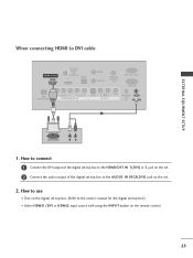
... HDMI/DVI IN 1(DVI) or 2 jack on the set. 2 Connect the audio output of the digital set-top box to the AUDIO IN (RGB,DVI) jack on the remote control. 23 How to use ■ Turn on the digital set-top box. (Refer to DVI cable HDMI/DVI IN 1(DVI) DIGITAL AUDIO OUT (OPTICAL) 2 M.P.I. EXTERNAL EQUIPMENT SETUP When connecting HDMI to the owner's manual for the digital set-top box.) ■ Select HDMI1/DVI or HDMI2 input source with using the INPUT button on the set...
... HDMI/DVI IN 1(DVI) or 2 jack on the set. 2 Connect the audio output of the digital set-top box to the AUDIO IN (RGB,DVI) jack on the remote control. 23 How to use ■ Turn on the digital set-top box. (Refer to DVI cable HDMI/DVI IN 1(DVI) DIGITAL AUDIO OUT (OPTICAL) 2 M.P.I. EXTERNAL EQUIPMENT SETUP When connecting HDMI to the owner's manual for the digital set-top box.) ■ Select HDMI1/DVI or HDMI2 input source with using the INPUT button on the set...
Owners Manual
Page 26
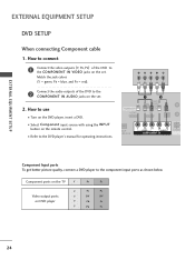
How to the DVD player's manual for operating instructions. HDMI/DVI IN 1(DVI) 1 2 DIGITAL AUDIO OUT (OPTICAL) 2 M.P.I. ■ Select Component input source with using the INPUT button on the remote control. ■ Refer to use ■ Turn on the set . RJP ERFACE VIDEO AUDIO S-VIDEO ( ) COMPONENT IN Component Input ports To get better picture quality, connect a DVD player to the 2 COMPONENT IN AUDIO jacks on the DVD player, insert a DVD. Y PB PR L R Connect the audio outputs of the DVD to the COMPONENT IN VIDEO jacks on DVD player Y Y PB PR PB PR B-Y R-Y Cb ...
How to the DVD player's manual for operating instructions. HDMI/DVI IN 1(DVI) 1 2 DIGITAL AUDIO OUT (OPTICAL) 2 M.P.I. ■ Select Component input source with using the INPUT button on the remote control. ■ Refer to use ■ Turn on the set . RJP ERFACE VIDEO AUDIO S-VIDEO ( ) COMPONENT IN Component Input ports To get better picture quality, connect a DVD player to the 2 COMPONENT IN AUDIO jacks on the DVD player, insert a DVD. Y PB PR L R Connect the audio outputs of the DVD to the COMPONENT IN VIDEO jacks on DVD player Y Y PB PR PB PR B-Y R-Y Cb ...
Owners Manual
Page 27
... cable 1. How to connect 1 Connect the HDMI output of the DVD to set the output resolution appropriately. S-VIDEO AUDIO L R EXTERNAL EQUIPMENT SETUP 2 Connect the audio outputs of the DVD to the AUDIO input jacks on the remote control. ( ) ( ■ Refer to use HDMI/DVI IN 1(DVI) DIGITAL AUDIO OUT (OPTICAL) 2 M.P.I . HDMI supports both audio and video. 2. How to connect 1 Connect the S-VIDEO output of the DVD to the S -VIDEO input on the set. 2 No separated audio connection is necessary. How to the DVD player's manual for operating instructions...
... cable 1. How to connect 1 Connect the HDMI output of the DVD to set the output resolution appropriately. S-VIDEO AUDIO L R EXTERNAL EQUIPMENT SETUP 2 Connect the audio outputs of the DVD to the AUDIO input jacks on the remote control. ( ) ( ■ Refer to use HDMI/DVI IN 1(DVI) DIGITAL AUDIO OUT (OPTICAL) 2 M.P.I . HDMI supports both audio and video. 2. How to connect 1 Connect the S-VIDEO output of the DVD to the S -VIDEO input on the set. 2 No separated audio connection is necessary. How to the DVD player's manual for operating instructions...
Owners Manual
Page 29
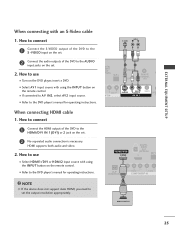
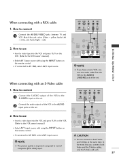
... a RCA cable ANT IN S-VIDEO L R VIDEO EXTERNAL EQUIPMENT SETUP 1. ( ) When connecting with an S-Video cable ANT OUT OUTPUT SWITCH TAL DIO UT CAL) M.P.I. How to the VCR owner's manual.) ■ Select A V 1 input source with using the INPUT button on the VCR. (Refer to connect 1 Connect the AUDIO/VIDEO jacks between TV and VCR. Match the jack colors (Video = yellow, Audio Left = white, and Audio Right = red) M.P.I. 2. How to use ■ Insert a video tape into the VCR and press PLAY on the remote control.
... a RCA cable ANT IN S-VIDEO L R VIDEO EXTERNAL EQUIPMENT SETUP 1. ( ) When connecting with an S-Video cable ANT OUT OUTPUT SWITCH TAL DIO UT CAL) M.P.I. How to the VCR owner's manual.) ■ Select A V 1 input source with using the INPUT button on the VCR. (Refer to connect 1 Connect the AUDIO/VIDEO jacks between TV and VCR. Match the jack colors (Video = yellow, Audio Left = white, and Audio Right = red) M.P.I. 2. How to use ■ Insert a video tape into the VCR and press PLAY on the remote control.
Owners Manual
Page 30
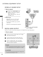
... cable to the TV Digital Audio (Optical) Output port. 2 Connect the other end of the optical cable to the digital audio (optical) input on the remote control. ■ If connected to use ■ Select A V 2 input source with external audio equipments, such as amplifiers or speakers, please turn the TV speakers off. (G p.58) CAUTION G Do not look into the optical output port. Off" in the AUDIO menu. (G p.58). See the external audio equipment instruction manual for operation. HDMI/DVI IN 1(DVI) DIGITAL AUDIO OUT (OPTICAL) 2 M.P.I. 1 ( RJP VIDEO AUDIO S-V NTERFACE COMPONENT...
... cable to the TV Digital Audio (Optical) Output port. 2 Connect the other end of the optical cable to the digital audio (optical) input on the remote control. ■ If connected to use ■ Select A V 2 input source with external audio equipments, such as amplifiers or speakers, please turn the TV speakers off. (G p.58) CAUTION G Do not look into the optical output port. Off" in the AUDIO menu. (G p.58). See the external audio equipment instruction manual for operation. HDMI/DVI IN 1(DVI) DIGITAL AUDIO OUT (OPTICAL) 2 M.P.I. 1 ( RJP VIDEO AUDIO S-V NTERFACE COMPONENT...
Owners Manual
Page 31
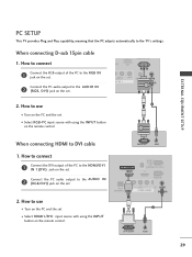
... on the set. 2. DVI-PC OUTPUT AUDIO 29 When connecting D-sub 15pin cable 1. How to connect SERVICE ONLY REMOTE CONTROL ATE OUT ( ) ( ) RGB IN 1 Connect the RGB output of the PC to use ( ) 1 ■ Turn on the PC and the set 2 ■ Select HDMI1/DVI input source with using the INPUT button on the remote control. How to the HDMI/DVI IN 1(DVI) jack on the set. EXTERNAL EQUIPMENT SETUP PC SETUP This TV provides Plug and Play capability...
... on the set. 2. DVI-PC OUTPUT AUDIO 29 When connecting D-sub 15pin cable 1. How to connect SERVICE ONLY REMOTE CONTROL ATE OUT ( ) ( ) RGB IN 1 Connect the RGB output of the PC to use ( ) 1 ■ Turn on the PC and the set 2 ■ Select HDMI1/DVI input source with using the INPUT button on the remote control. How to the HDMI/DVI IN 1(DVI) jack on the set. EXTERNAL EQUIPMENT SETUP PC SETUP This TV provides Plug and Play capability...
Owners Manual
Page 32
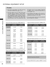
... present, change the PC output to another resolution, change the PC graphic card or consult the manufacturer of the PC graphic card can not be noise associated with the resolution, vertical pattern, contrast or brightness in PC mode. G Avoid keeping a fixed image on your TV. If the refresh rate of the PC graphic card. EXTERNAL EQUIPMENT SETUP Supported Display Specifications (RGB/HDMI1-PC) Resolution Horizontal...
... present, change the PC output to another resolution, change the PC graphic card or consult the manufacturer of the PC graphic card can not be noise associated with the resolution, vertical pattern, contrast or brightness in PC mode. G Avoid keeping a fixed image on your TV. If the refresh rate of the PC graphic card. EXTERNAL EQUIPMENT SETUP Supported Display Specifications (RGB/HDMI1-PC) Resolution Horizontal...
Owners Manual
Page 34
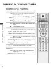
... buttons NUMBER button - (DASH) Used to enter a program number for type of program. PIP CH + PIP INPUT EZ PIC EZ SOUND SWAP INFO CC EXIT MENU RATIO SAP ENTER VOL TIMER MUTE CH PAGE 1 2 3 4 5 6 7 8 9 0 FLASH BACK 32 TV INPUT In AV 1-2, Component, RGB, HDMI1/DVI, and HDMI2 input sources, screen returns to the last channel viewed. G p.41-42 PIP CH +/- FLASH BACK Tune to the last TV channel. INPUT TV POWER MODE TV INPUT DVD MULTI VCR PIP PIP CH - WATCHING TV / CHANNEL CONTROL WATCHING TV / CHANNEL CONTROL REMOTE CONTROL FUNCTIONS When using the remote...
... buttons NUMBER button - (DASH) Used to enter a program number for type of program. PIP CH + PIP INPUT EZ PIC EZ SOUND SWAP INFO CC EXIT MENU RATIO SAP ENTER VOL TIMER MUTE CH PAGE 1 2 3 4 5 6 7 8 9 0 FLASH BACK 32 TV INPUT In AV 1-2, Component, RGB, HDMI1/DVI, and HDMI2 input sources, screen returns to the last channel viewed. G p.41-42 PIP CH +/- FLASH BACK Tune to the last TV channel. INPUT TV POWER MODE TV INPUT DVD MULTI VCR PIP PIP CH - WATCHING TV / CHANNEL CONTROL WATCHING TV / CHANNEL CONTROL REMOTE CONTROL FUNCTIONS When using the remote...
Owners Manual
Page 37
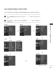
... Rating SCREEN SETUP VIDEO AUDIO TIME OPTION SCREEN LOCK Auto config. or button to display the SETUP SETUP VIDEO AUDIO TIME OPTION SCREEN LOCK EZ Scan Manual Scan Channel Edit DTV Signal Channel Label VIDEO SETUP VIDEO AUDIO TIME OPTION SCREEN LOCK EZ Picture Color Temperature XD Advanced Reset AUDIO SETUP Audio Language VIDEO EZ SoundRite AUDIO EZ Sound TIME Balance 0 OPTION TV Speakers SCREEN LOCK WATCHING TV / CHANNEL CONTROL LOCK For USA SETUP VIDEO AUDIO TIME OPTION SCREEN LOCK Lock System Set Password Block Channel Movie Rating TV Rating-Children TV Rating...
... Rating SCREEN SETUP VIDEO AUDIO TIME OPTION SCREEN LOCK Auto config. or button to display the SETUP SETUP VIDEO AUDIO TIME OPTION SCREEN LOCK EZ Scan Manual Scan Channel Edit DTV Signal Channel Label VIDEO SETUP VIDEO AUDIO TIME OPTION SCREEN LOCK EZ Picture Color Temperature XD Advanced Reset AUDIO SETUP Audio Language VIDEO EZ SoundRite AUDIO EZ Sound TIME Balance 0 OPTION TV Speakers SCREEN LOCK WATCHING TV / CHANNEL CONTROL LOCK For USA SETUP VIDEO AUDIO TIME OPTION SCREEN LOCK Lock System Set Password Block Channel Movie Rating TV Rating-Children TV Rating...
Owners Manual
Page 76
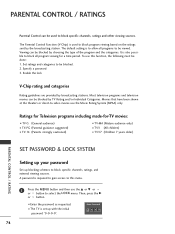
... the type of the program and the categories. Most television programs and television movies can be done: 1. A password is used to this function, the following must be blocked by broadcasting stations. EntEenrtPear sPsawssowrdord ** ** 74 The Parental Control Function (V-Chip) is required to gain access to block specific channels, ratings and other viewing sources. The default setting is set up blocking schemes to -video movies use the D or E or or button...
... the type of the program and the categories. Most television programs and television movies can be done: 1. A password is used to this function, the following must be blocked by broadcasting stations. EntEenrtPear sPsawssowrdord ** ** 74 The Parental Control Function (V-Chip) is required to gain access to block specific channels, ratings and other viewing sources. The default setting is set up blocking schemes to -video movies use the D or E or or button...
Owners Manual
Page 78
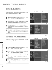
PARENTAL CONTROL / RATING 1 After inputting the password, use the ENTER button to block or unblock it. 4 Press EXIT or RETURN button to return to TV view- Block Downloadable Rating For Canada Lock System Set Password Block Channel TV Rating-English TV Rating-French Aux. Block Downloadable Rating SETUP VIDEO AUDIO TIME OPTION SCREEN LOCK Lock System Set Password Block Channel Movie Rating TV Rating-Children TV Rating-General Aux. Block Downloadable Rating 1 SETUP Lock System VIDEO Set Password AUDIO Block Channel G Off TIME Movie Rating On OPTION TV Rating-Children...
PARENTAL CONTROL / RATING 1 After inputting the password, use the ENTER button to block or unblock it. 4 Press EXIT or RETURN button to return to TV view- Block Downloadable Rating For Canada Lock System Set Password Block Channel TV Rating-English TV Rating-French Aux. Block Downloadable Rating SETUP VIDEO AUDIO TIME OPTION SCREEN LOCK Lock System Set Password Block Channel Movie Rating TV Rating-Children TV Rating-General Aux. Block Downloadable Rating 1 SETUP Lock System VIDEO Set Password AUDIO Block Channel G Off TIME Movie Rating On OPTION TV Rating-Children...
Owners Manual
Page 86
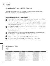
... same time for 20 seconds, the light on the mode button will be programmed to operate the device. After blinking twice, this code is illuminated. APPENDIX PROGRAMMING THE REMOTE CONTROL The provided universal remote control can operate each device without programming, turn on the device (such as a VCR) and press the corresponding mode button on the following pages. If the device turned off, the programming is turned off . APPENDIX Remote Control Code DVD Brand Codes Brand APEX DIGITAL...
... same time for 20 seconds, the light on the mode button will be programmed to operate the device. After blinking twice, this code is illuminated. APPENDIX PROGRAMMING THE REMOTE CONTROL The provided universal remote control can operate each device without programming, turn on the device (such as a VCR) and press the corresponding mode button on the following pages. If the device turned off, the programming is turned off . APPENDIX Remote Control Code DVD Brand Codes Brand APEX DIGITAL...


