Owners Manual
Page 2
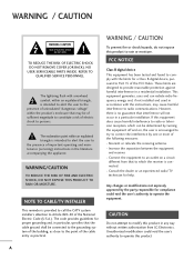
... occur in a particular installation. CAUTION Do not attempt to modify this equipment does cause harmful interference to radio or television reception, which the receiver is intended to alert the user to Part 15 of the following measures: - NO USER SERVICEABLE PARTS INSIDE. These limits are designed to Article 820-40 of important operating and maintenance (servicing) instructions in particular, specifies that...
... occur in a particular installation. CAUTION Do not attempt to modify this equipment does cause harmful interference to radio or television reception, which the receiver is intended to alert the user to Part 15 of the following measures: - NO USER SERVICEABLE PARTS INSIDE. These limits are designed to Article 820-40 of important operating and maintenance (servicing) instructions in particular, specifies that...

Owners Manual
Page 5
20 ANTENNAS Outdoor antenna grounding If an outdoor antenna is turned off, unplugged and all cables have been removed. Section 810 of overhead power lines or other odors coming from the TV or hear strange sounds, unplug the power cord contact an authorized service center. 25 Do not press strongly upon the panel with respect to proper grounding of the mast and supporting structure, grounding...
20 ANTENNAS Outdoor antenna grounding If an outdoor antenna is turned off, unplugged and all cables have been removed. Section 810 of overhead power lines or other odors coming from the TV or hear strange sounds, unplug the power cord contact an authorized service center. 25 Do not press strongly upon the panel with respect to proper grounding of the mast and supporting structure, grounding...

Owners Manual
Page 6
...65 Auto Clock Setup 65 Manual Clock Setup 66 Auto On/Off Timer Setting 67 Auto Shut-off Setting 68 Sleep Timer Setting 69 SCREEN ADJUSTMENT Auto Configure (RGB(PC) Mode only 70 Manual Configure 71 Selecting XGA Mode 72 Initializing (Reset to a Desk 18 VESA Wall Mounting 19 Desktop Pedestal Installation 19 Antenna or Cable Connection 20 EXTERNAL EQUIPMENT SETUP HD Receiver Setup 21 DVD Setup 24 VCR Setup 26 Other A/V Source Setup 28 Digital Audio Output 28 PC Setup 29 WATCHING TV / CHANNEL CONTROL Remote Control Functions 32 Turning On TV 34 Channel Selection 34 Volume...
...65 Auto Clock Setup 65 Manual Clock Setup 66 Auto On/Off Timer Setting 67 Auto Shut-off Setting 68 Sleep Timer Setting 69 SCREEN ADJUSTMENT Auto Configure (RGB(PC) Mode only 70 Manual Configure 71 Selecting XGA Mode 72 Initializing (Reset to a Desk 18 VESA Wall Mounting 19 Desktop Pedestal Installation 19 Antenna or Cable Connection 20 EXTERNAL EQUIPMENT SETUP HD Receiver Setup 21 DVD Setup 24 VCR Setup 26 Other A/V Source Setup 28 Digital Audio Output 28 PC Setup 29 WATCHING TV / CHANNEL CONTROL Remote Control Functions 32 Turning On TV 34 Channel Selection 34 Volume...
Owners Manual
Page 11
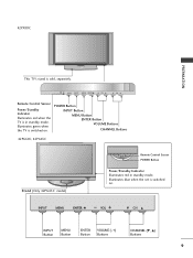
...42PX8DC PREPARATION INPUT ENTER This TV's stand is switched on . INPUT MENU ENTER VOL CH INPUT MENU ENTER VOL CH INPUT MENU ENTER VOL CH INPUT Button MENU Button ENTER Button VOLUME (-,+) Buttons CHANNEL (E, D) Buttons 9 POWER Button INPUT Button MENU Button ENTER Button VOLUME Buttons CHANNEL Buttons 42PG60C, 42PG65C Stand (Only 42PG65C model) Remote Control Sensor POWER Button Power/Standby Indicator Illuminates red in standby mode. INPUT ENTER Illuminates blue when the set is sold, separately. Illuminates green when the TV is in standby mode.
...42PX8DC PREPARATION INPUT ENTER This TV's stand is switched on . INPUT MENU ENTER VOL CH INPUT MENU ENTER VOL CH INPUT MENU ENTER VOL CH INPUT Button MENU Button ENTER Button VOLUME (-,+) Buttons CHANNEL (E, D) Buttons 9 POWER Button INPUT Button MENU Button ENTER Button VOLUME Buttons CHANNEL Buttons 42PG60C, 42PG65C Stand (Only 42PG65C model) Remote Control Sensor POWER Button Power/Standby Indicator Illuminates red in standby mode. INPUT ENTER Illuminates blue when the set is sold, separately. Illuminates green when the TV is in standby mode.
Owners Manual
Page 13
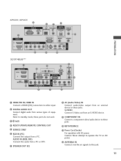
... input. 2 DIGITAL AUDIO OUT Connect digital audio from an S-VIDEO device. 9 COMPONENT IN Connect a component video/audio device to these jacks. Note: In standby mode, these ports do not work. 3 13 M.P.I 4 RESET/UPDATE/REMOTE CONTROL OUT 5 SERVICE ONLY 6 RGB IN (PC) Connect the output from an external device to this jack. 11 AUDIO IN (RGB, DVI) Connect the audio from a PC or DTV. 7 SPEAKER OUT 8Ω 8 AV (Audio/Video) IN Connect audio/video output from a PC. Caution: Never attempt to operate the TV on DC power. 12 ANTENNA...
... input. 2 DIGITAL AUDIO OUT Connect digital audio from an S-VIDEO device. 9 COMPONENT IN Connect a component video/audio device to these jacks. Note: In standby mode, these ports do not work. 3 13 M.P.I 4 RESET/UPDATE/REMOTE CONTROL OUT 5 SERVICE ONLY 6 RGB IN (PC) Connect the output from an external device to this jack. 11 AUDIO IN (RGB, DVI) Connect the audio from a PC or DTV. 7 SPEAKER OUT 8Ω 8 AV (Audio/Video) IN Connect audio/video output from a PC. Caution: Never attempt to operate the TV on DC power. 12 ANTENNA...
Owners Manual
Page 21
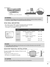
... models. A B Product LCD TV PLASMA TV Model 32LC5DC*, 32LC50C*, 32LX5DC*, 32LX50C*, 32LG5*** 37LG5***, 42LG5*** 32/37/42LC5DC*, 32/37/42LC50C*, 42LB5DC, 42LB50C 42PG60C 42PX8DC VESA (A * B) 200 * 100 200 * 200 600 * 400 400 * 400 600 * 400 NOTE G Screw length needed depends on each side from falling over, the TV should be securely attached to the VESA Wall Mounting Instruction Guide. For further information, refer to the floor/wall per installation instructions...
... models. A B Product LCD TV PLASMA TV Model 32LC5DC*, 32LC50C*, 32LX5DC*, 32LX50C*, 32LG5*** 37LG5***, 42LG5*** 32/37/42LC5DC*, 32/37/42LC50C*, 42LB5DC, 42LB50C 42PG60C 42PX8DC VESA (A * B) 200 * 100 200 * 200 600 * 400 400 * 400 600 * 400 NOTE G Screw length needed depends on each side from falling over, the TV should be securely attached to the VESA Wall Mounting Instruction Guide. For further information, refer to the floor/wall per installation instructions...
Owners Manual
Page 23
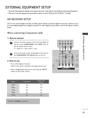
... connecting Component cable 1. Match the jack colors (Y = green, PB = blue, and PR = red). How to use picture for the digital set-top box.) ■ Select Component input source with using the INPUT button on the digital set-top box. (Refer to the owner's manual for LCD TV(Except 32/37/42LG5***) models. HD RECEIVER SETUP This TV can receive Digital Over-the-air/Cable signals without an external digital set-top box. RJP RFACE VIDEO AUDIO S-VIDEO ( ) COMPONENT IN Signal 480i 480p 720p 1080i 1080p Component Yes Yes Yes Yes Yes * 42LB5DC, 42LB50C model...
... connecting Component cable 1. Match the jack colors (Y = green, PB = blue, and PR = red). How to use picture for the digital set-top box.) ■ Select Component input source with using the INPUT button on the digital set-top box. (Refer to the owner's manual for LCD TV(Except 32/37/42LG5***) models. HD RECEIVER SETUP This TV can receive Digital Over-the-air/Cable signals without an external digital set-top box. RJP RFACE VIDEO AUDIO S-VIDEO ( ) COMPONENT IN Signal 480i 480p 720p 1080i 1080p Component Yes Yes Yes Yes Yes * 42LB5DC, 42LB50C model...
Owners Manual
Page 24
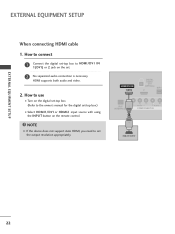
... owner's manual for the digital set-top box.) ■ Select HDMI1/DVI or HDMI2 input source with using the INPUT button on the set. 2 No separated audio connection is necessary. HDMI/DVI IN 1(DVI) DIGITAL AUDIO OUT (OPTICAL) 2 M.P.I RJP INTERFACE 1 VIDEO AUDIO COMPONENT IN HDMI-DTV OUTPUT ( ) 22 EXTERNAL EQUIPMENT SETUP EXTERNAL EQUIPMENT SETUP When connecting HDMI cable 1. How to HDMI/DVI IN 1(DVI) or 2 jack on the remote control. NOTE G If the device does not support Auto HDMI, you need to set -top box to connect 1 Connect the digital set the output resolution...
... owner's manual for the digital set-top box.) ■ Select HDMI1/DVI or HDMI2 input source with using the INPUT button on the set. 2 No separated audio connection is necessary. HDMI/DVI IN 1(DVI) DIGITAL AUDIO OUT (OPTICAL) 2 M.P.I RJP INTERFACE 1 VIDEO AUDIO COMPONENT IN HDMI-DTV OUTPUT ( ) 22 EXTERNAL EQUIPMENT SETUP EXTERNAL EQUIPMENT SETUP When connecting HDMI cable 1. How to HDMI/DVI IN 1(DVI) or 2 jack on the remote control. NOTE G If the device does not support Auto HDMI, you need to set -top box to connect 1 Connect the digital set the output resolution...

Owners Manual
Page 25
... cable HDMI/DVI IN 1(DVI) DIGITAL AUDIO OUT (OPTICAL) 2 M.P.I. How to use ■ Turn on the digital set-top box. (Refer to the owner's manual for the digital set-top box.) ■ Select HDMI1/DVI or HDMI2 input source with using the INPUT button on the set. 2 Connect the audio output of the digital set -top box to the HDMI/DVI IN 1(DVI) or 2 jack on the remote control. 23 RESET UPDATE REMOTE CONTROL OUT SERVICE ONLY RGB IN RJP INTERFACE 1 VIDEO AUDIO COMPONENT IN S-VIDEO (MONO) AUDIO AV IN 1 VIDEO SPEAKER AUDIO...
... cable HDMI/DVI IN 1(DVI) DIGITAL AUDIO OUT (OPTICAL) 2 M.P.I. How to use ■ Turn on the digital set-top box. (Refer to the owner's manual for the digital set-top box.) ■ Select HDMI1/DVI or HDMI2 input source with using the INPUT button on the set. 2 Connect the audio output of the digital set -top box to the HDMI/DVI IN 1(DVI) or 2 jack on the remote control. 23 RESET UPDATE REMOTE CONTROL OUT SERVICE ONLY RGB IN RJP INTERFACE 1 VIDEO AUDIO COMPONENT IN S-VIDEO (MONO) AUDIO AV IN 1 VIDEO SPEAKER AUDIO...

Owners Manual
Page 26
...remote control. ■ Refer to the component input ports as shown below. Match the jack colors (Y = green, PB = blue, and PR = red). RJP ERFACE VIDEO AUDIO S-VIDEO ( ) COMPONENT IN Component Input ports To get better picture quality, connect a DVD player to the DVD player's manual for operating instructions. Component ports on the TV Y Y Video output ports Y on the DVD player, insert a DVD. How to the COMPONENT IN VIDEO jacks on the set . 2. HDMI/DVI IN 1(DVI) 1 2 DIGITAL AUDIO OUT (OPTICAL) 2 M.P.I. ■ Select Component input source with using the INPUT...
...remote control. ■ Refer to the component input ports as shown below. Match the jack colors (Y = green, PB = blue, and PR = red). RJP ERFACE VIDEO AUDIO S-VIDEO ( ) COMPONENT IN Component Input ports To get better picture quality, connect a DVD player to the DVD player's manual for operating instructions. Component ports on the TV Y Y Video output ports Y on the DVD player, insert a DVD. How to the COMPONENT IN VIDEO jacks on the set . 2. HDMI/DVI IN 1(DVI) 1 2 DIGITAL AUDIO OUT (OPTICAL) 2 M.P.I. ■ Select Component input source with using the INPUT...

Owners Manual
Page 27
... connecting HDMI cable 1. RJP INTERFACE VIDEO AUDIO COMPONENT IN 1 NOTE G If the device does not support Auto HDMI, you need to the DVD player's manual for operating instructions. 1 2 GITAL UDIO OUT RESET TICAL) M.P.I ■ Select HDMI1/DVI or HDMI2 input source with using the INPUT button on the remote control. ■ If connected to AV IN2, select A V 2 input source. ■ Refer to the S -VIDEO input on the remote control. ( ) ( ■ Refer to set the output resolution appropriately. How to use HDMI/DVI IN 1(DVI) DIGITAL AUDIO OUT (OPTICAL) 2 M.P.I . HDMI...
... connecting HDMI cable 1. RJP INTERFACE VIDEO AUDIO COMPONENT IN 1 NOTE G If the device does not support Auto HDMI, you need to the DVD player's manual for operating instructions. 1 2 GITAL UDIO OUT RESET TICAL) M.P.I ■ Select HDMI1/DVI or HDMI2 input source with using the INPUT button on the remote control. ■ If connected to AV IN2, select A V 2 input source. ■ Refer to the S -VIDEO input on the remote control. ( ) ( ■ Refer to set the output resolution appropriately. How to use HDMI/DVI IN 1(DVI) DIGITAL AUDIO OUT (OPTICAL) 2 M.P.I . HDMI...
Owners Manual
Page 29
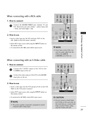
... owner's manual.) ■ Select A V 1 input source with using the INPUT button on the remote control. ■ If connected to the S -VIDEO input on the set . ( ) When connecting with an S-Video cable ANT OUT OUTPUT SWITCH TAL DIO UT CAL) M.P.I. CAUTION G Do not connect to the VCR owner's manual.) ■ Select A V 1 input source with using the INPUT button on the VCR. (Refer to both Video and the S-Video cables, only the S-Video will work. 27 Match the jack colors (Video = yellow, Audio Left = white, and Audio Right = red...
... owner's manual.) ■ Select A V 1 input source with using the INPUT button on the remote control. ■ If connected to the S -VIDEO input on the set . ( ) When connecting with an S-Video cable ANT OUT OUTPUT SWITCH TAL DIO UT CAL) M.P.I. CAUTION G Do not connect to the VCR owner's manual.) ■ Select A V 1 input source with using the INPUT button on the VCR. (Refer to both Video and the S-Video cables, only the S-Video will work. 27 Match the jack colors (Video = yellow, Audio Left = white, and Audio Right = red...
Owners Manual
Page 30
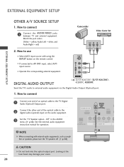
... instruction manual for operation. Match the jack colors. (Video = yellow, Audio Left = white, and Audio Right = red) Camcorder Video Game Set VIDEO L R 2. S-VIDEO 1 VIDEO L/MONO AUDIO R AV IN 2 DIGITAL AUDIO OUTPUT i.e) 32/37/42LC5DC*, 32/37/42LC50C*, 42LB5DC, 42LB50C Send the TV's audio to connect 1 Connect the AUDIO/VIDEO jacks between TV and external equipment. HDMI/DVI IN 1(DVI) DIGITAL AUDIO OUT (OPTICAL) 2 M.P.I. 1 ( RJP VIDEO AUDIO S-V NTERFACE COMPONENT IN 2 NOTE G When connecting with using the INPUT button on the audio equipment. 3 Set the "TV Speaker...
... instruction manual for operation. Match the jack colors. (Video = yellow, Audio Left = white, and Audio Right = red) Camcorder Video Game Set VIDEO L R 2. S-VIDEO 1 VIDEO L/MONO AUDIO R AV IN 2 DIGITAL AUDIO OUTPUT i.e) 32/37/42LC5DC*, 32/37/42LC50C*, 42LB5DC, 42LB50C Send the TV's audio to connect 1 Connect the AUDIO/VIDEO jacks between TV and external equipment. HDMI/DVI IN 1(DVI) DIGITAL AUDIO OUT (OPTICAL) 2 M.P.I. 1 ( RJP VIDEO AUDIO S-V NTERFACE COMPONENT IN 2 NOTE G When connecting with using the INPUT button on the audio equipment. 3 Set the "TV Speaker...
Owners Manual
Page 31
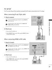
... on the set . EXTERNAL EQUIPMENT SETUP PC SETUP This TV provides Plug and Play capability, meaning that the PC adjusts automatically to the AUDIO IN 2 (RGB, DVI) jack on the set 2 ■ Select HDMI1/DVI input source with using the INPUT button on the remote control. RGB IN ( ) ( ) RJP INTERFACE VIDEO ER AUDIO COMPONENT IN (RGB, DVI) 2. HDMI/DVI IN 1(DVI) DIGITA AUDIO OUT (OPTICA VICE ONLY 2 Connect the PC audio output to use ■ Turn on...
... on the set . EXTERNAL EQUIPMENT SETUP PC SETUP This TV provides Plug and Play capability, meaning that the PC adjusts automatically to the AUDIO IN 2 (RGB, DVI) jack on the set 2 ■ Select HDMI1/DVI input source with using the INPUT button on the remote control. RGB IN ( ) ( ) RJP INTERFACE VIDEO ER AUDIO COMPONENT IN (RGB, DVI) 2. HDMI/DVI IN 1(DVI) DIGITA AUDIO OUT (OPTICA VICE ONLY 2 Connect the PC audio output to use ■ Turn on...
Owners Manual
Page 32
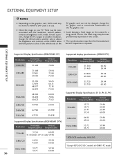
... use. There may be changed, change the refresh rate to another resolution, change the PC graphic card or consult the manufacturer of the PC graphic card. G Avoid keeping a fixed image on the screen for Horizontal and Vertical frequencies is separate. EXTERNAL EQUIPMENT SETUP NOTES G Depending on the graphics card, DOS mode may not work if a HDMI to DVI Cable is in PC mode. EXTERNAL EQUIPMENT SETUP Supported Display Specifications...
... use. There may be changed, change the refresh rate to another resolution, change the PC graphic card or consult the manufacturer of the PC graphic card. G Avoid keeping a fixed image on the screen for Horizontal and Vertical frequencies is separate. EXTERNAL EQUIPMENT SETUP NOTES G Depending on the graphics card, DOS mode may not work if a HDMI to DVI Cable is in PC mode. EXTERNAL EQUIPMENT SETUP Supported Display Specifications...

Owners Manual
Page 34
... mode. Adjusts brightness on the TV. PIP Switches the sub picture Double Window or off , depending on the viewing EZ PIC environment. G p.42 PIP INPUT Select the connected input source for type of program. G p.55 SWAP(or PIP SWAP) Exchange the main/sub images. INPUT TV POWER MODE TV INPUT DVD MULTI VCR PIP PIP CH - Changes the PIP channel. control buttons NUMBER button - (DASH) Used to the last channel viewed. WATCHING TV / CHANNEL CONTROL WATCHING TV / CHANNEL CONTROL REMOTE CONTROL FUNCTIONS When using the remote control, aim it at the remote control sensor on screen...
... mode. Adjusts brightness on the TV. PIP Switches the sub picture Double Window or off , depending on the viewing EZ PIC environment. G p.42 PIP INPUT Select the connected input source for type of program. G p.55 SWAP(or PIP SWAP) Exchange the main/sub images. INPUT TV POWER MODE TV INPUT DVD MULTI VCR PIP PIP CH - Changes the PIP channel. control buttons NUMBER button - (DASH) Used to the last channel viewed. WATCHING TV / CHANNEL CONTROL WATCHING TV / CHANNEL CONTROL REMOTE CONTROL FUNCTIONS When using the remote control, aim it at the remote control sensor on screen...
Owners Manual
Page 37
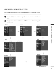
... EZ Scan Manual Scan Channel Edit DTV Signal Channel Label VIDEO SETUP VIDEO AUDIO TIME OPTION SCREEN LOCK EZ Picture Color Temperature XD Advanced Reset AUDIO SETUP Audio Language VIDEO EZ SoundRite AUDIO EZ Sound TIME Balance 0 OPTION TV Speakers SCREEN LOCK WATCHING TV / CHANNEL CONTROL LOCK For USA SETUP VIDEO AUDIO TIME OPTION SCREEN LOCK Lock System Set Password Block Channel Movie Rating TV Rating-Children TV Rating-General Aux. ON-SCREEN MENUS SELECTION Your TV's OSD (On Screen Display) may differ slightly from what is shown in this manual. 1 Press the MENU button...
... EZ Scan Manual Scan Channel Edit DTV Signal Channel Label VIDEO SETUP VIDEO AUDIO TIME OPTION SCREEN LOCK EZ Picture Color Temperature XD Advanced Reset AUDIO SETUP Audio Language VIDEO EZ SoundRite AUDIO EZ Sound TIME Balance 0 OPTION TV Speakers SCREEN LOCK WATCHING TV / CHANNEL CONTROL LOCK For USA SETUP VIDEO AUDIO TIME OPTION SCREEN LOCK Lock System Set Password Block Channel Movie Rating TV Rating-Children TV Rating-General Aux. ON-SCREEN MENUS SELECTION Your TV's OSD (On Screen Display) may differ slightly from what is shown in this manual. 1 Press the MENU button...
Owners Manual
Page 76
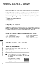
... block specific channels, ratings, and external viewing sources. Specify a password 3. EntEenrtPear sPsawssowrdord ** ** 74 Set ratings and categories to -video movies use the D or E or or button to select the LOCK menu. Most television programs and television movies can be blocked by broadcasting stations. Then, press the G or button. ■ Enter the password as requested. ■ The TV is also possible to block all programs to be viewed. Ratings for Television programs including...
... block specific channels, ratings, and external viewing sources. Specify a password 3. EntEenrtPear sPsawssowrdord ** ** 74 Set ratings and categories to -video movies use the D or E or or button to select the LOCK menu. Most television programs and television movies can be blocked by broadcasting stations. Then, press the G or button. ■ Enter the password as requested. ■ The TV is also possible to block all programs to be viewed. Ratings for Television programs including...

Owners Manual
Page 78
... MENU button to return to the previous menu. EXTERNAL INPUT BLOCKING Enables you to select a source to block from the external source devices you do not want your children to watch or that you have hooked up. Block Downloadable Rating For Canada Lock System Set Password Block Channel TV Rating-English TV Rating-French Aux. Block Downloadable Rating For Canada Lock System Set Password Block Channel TV Rating-English TV Rating-French Aux. PARENTAL CONTROL...
... MENU button to return to the previous menu. EXTERNAL INPUT BLOCKING Enables you to select a source to block from the external source devices you do not want your children to watch or that you have hooked up. Block Downloadable Rating For Canada Lock System Set Password Block Channel TV Rating-English TV Rating-French Aux. Block Downloadable Rating For Canada Lock System Set Password Block Channel TV Rating-English TV Rating-French Aux. PARENTAL CONTROL...

Owners Manual
Page 86
... explained below. 2 Press the MENU and MUTE button continuously at a time. the currently selected device button is stored. 5 Test the remote control functions to store the code. When pressing the button, the light blinks at the same time for 20 seconds, the light on the remote. After blinking twice, this code is illuminated. APPENDIX PROGRAMMING THE REMOTE CONTROL The provided universal remote control can operate each device without programming, turn on the device (such...
... explained below. 2 Press the MENU and MUTE button continuously at a time. the currently selected device button is stored. 5 Test the remote control functions to store the code. When pressing the button, the light blinks at the same time for 20 seconds, the light on the remote. After blinking twice, this code is illuminated. APPENDIX PROGRAMMING THE REMOTE CONTROL The provided universal remote control can operate each device without programming, turn on the device (such...


