
SD-513 User Manual
Page 8
... this machine, and performs management, maintenance, and troubleshooting for the following users of this ma- Saddle Stitcher SD-513 1-3 Administrator: A person who receives training from Konica Minolta or authorized partner , makes consumables management and system settings, and builds up a network environment or security system. Operator: A person who receives training from...
... this machine, and performs management, maintenance, and troubleshooting for the following users of this ma- Saddle Stitcher SD-513 1-3 Administrator: A person who receives training from Konica Minolta or authorized partner , makes consumables management and system settings, and builds up a network environment or security system. Operator: A person who receives training from...

GP-502 Operation Manual
Page 4
...;Black, Qty 200 Type#: Ring Binder RB-101 Black •Clear, .Qty 200: ......... Some customer benefits noted for this system include: • Docks to the Konica Minolta printer to combine printing, punching, collating, and binding into one convenient step. • Increases throughput of finishing applications with a completely automated process. • Creates books... document sizes. • Compared to print, punch and bind documents. Only one common Ellipse element. Documents flow directly from the printer to your high-speed Konica Minolta printer. 2.
...;Black, Qty 200 Type#: Ring Binder RB-101 Black •Clear, .Qty 200: ......... Some customer benefits noted for this system include: • Docks to the Konica Minolta printer to combine printing, punching, collating, and binding into one convenient step. • Increases throughput of finishing applications with a completely automated process. • Creates books... document sizes. • Compared to print, punch and bind documents. Only one common Ellipse element. Documents flow directly from the printer to your high-speed Konica Minolta printer. 2.

IQ-501 Quick Guide
Page 2
...Timing Procedure Page 1a. Both side adjustment (Step 18-30) - p.49 p.51 p.52 1 Print the job by /Konica Minolta controller (A) /EFI controller (B) /CREO controller (C) NOTICE This manual describes the procedures for the job with Trim Margin /Preparation...paper size (Step 1) - Conformation of Auto Image Adj. Setting Summary - Color Density Control setting (Step 1-7) - Print the job by /Konica Minolta controller (A) /EFI controller (B) /CREO controller (C) p.38 p.46 p.47 4a.Keep registration and constant color reproduction during long printing for the ...
...Timing Procedure Page 1a. Both side adjustment (Step 18-30) - p.49 p.51 p.52 1 Print the job by /Konica Minolta controller (A) /EFI controller (B) /CREO controller (C) NOTICE This manual describes the procedures for the job with Trim Margin /Preparation...paper size (Step 1) - Conformation of Auto Image Adj. Setting Summary - Color Density Control setting (Step 1-7) - Print the job by /Konica Minolta controller (A) /EFI controller (B) /CREO controller (C) p.38 p.46 p.47 4a.Keep registration and constant color reproduction during long printing for the ...

IQ-501 Quick Guide
Page 53
Konica Minolta controller/APPM, Printer driver >> A - 2/27/2020 5:45 PM/D11 4b. CREO controller/IC-314) >> C < Print the job > A Print long job with following settings AccurioPro Print Manager Open Job setting and go to [Quality]Tab - [Auto Image Adjustment] > [Off] Printer driver(KM controller) Go to [Quality Tab], then - [Auto Image Adjustment] > [Off] 52 Keep registration and constant color during long printing for the job without Trim Margin /Execution Print the job - EFI controller/CWS(v6,v5), Printer driver >> B -
Konica Minolta controller/APPM, Printer driver >> A - 2/27/2020 5:45 PM/D11 4b. CREO controller/IC-314) >> C < Print the job > A Print long job with following settings AccurioPro Print Manager Open Job setting and go to [Quality]Tab - [Auto Image Adjustment] > [Off] Printer driver(KM controller) Go to [Quality Tab], then - [Auto Image Adjustment] > [Off] 52 Keep registration and constant color during long printing for the job without Trim Margin /Execution Print the job - EFI controller/CWS(v6,v5), Printer driver >> B -

Fiery Server with Auto Inspection Guide
Page 1
... VI-511 • Upgrade Kit UK-301 • Video Interface Kit VI-513 • Relay Unit RU-702 Note: See the documentation included with your Konica Minolta printer to determine whether it supports Automatic inspection. Automatic inspection with a Fiery server Automatically detect and remove sheets containing imperfections from the proof print you...
... VI-511 • Upgrade Kit UK-301 • Video Interface Kit VI-513 • Relay Unit RU-702 Note: See the documentation included with your Konica Minolta printer to determine whether it supports Automatic inspection. Automatic inspection with a Fiery server Automatically detect and remove sheets containing imperfections from the proof print you...

Fiery Server with Auto Inspection Guide
Page 2
... ID created by using the latest proof Automatically inspect a job by the printer. For more information, see the documentation included with your Konica Minolta printer and printer accessories. 1 In Command WorkStation, add your job to the Held queue. 2 Open Job Properties and click the Image...print a copy of your job. 6 Retrieve the proof from the printer control panel. For more information, see the documentation included with your Konica Minolta printer and printer accessories. 1 In Command WorkStation, add your job to the Held queue. 2 Open Job Properties and click the Image tab...
... ID created by using the latest proof Automatically inspect a job by the printer. For more information, see the documentation included with your Konica Minolta printer and printer accessories. 1 In Command WorkStation, add your job to the Held queue. 2 Open Job Properties and click the Image...print a copy of your job. 6 Retrieve the proof from the printer control panel. For more information, see the documentation included with your Konica Minolta printer and printer accessories. 1 In Command WorkStation, add your job to the Held queue. 2 Open Job Properties and click the Image tab...

GBC PUNCH G2 User Manual
Page 10
... to the proper position. Glossary LEF- All square and round hole die sets follow the same pin numbering format. Important! Coil Rnd US Paper Sizes Konica Minolta Part Number LTR LEF 2, 47 LTR SEF 7, 42 STATEMENT LEF 7, 42 LEGAL SEF 7, 42 LEDGER SEF 2, 47 9" x 12" LEF 1, 2, 47 ... 3, 19 3, 21 NONE 3H/5H/7H N/A N/A N/A NONE N/A 1, 21 1, 23 Wire 3:1 Sq 1,34 5,31 5,31 5,31 1, 34 1, 34 5, 31 1, 34 Coil Rnd ISO Paper Sizes Konica Minolta Part Number A4 LEF NONE A4 SEF 7, 41 A5 LEF 7, 41 A3 SEF NONE SRA4 LEF NONE SRA4 SEF 6, 7, 42, 41 SRA3 SEF NONE Wire...
... to the proper position. Glossary LEF- All square and round hole die sets follow the same pin numbering format. Important! Coil Rnd US Paper Sizes Konica Minolta Part Number LTR LEF 2, 47 LTR SEF 7, 42 STATEMENT LEF 7, 42 LEGAL SEF 7, 42 LEDGER SEF 2, 47 9" x 12" LEF 1, 2, 47 ... 3, 19 3, 21 NONE 3H/5H/7H N/A N/A N/A NONE N/A 1, 21 1, 23 Wire 3:1 Sq 1,34 5,31 5,31 5,31 1, 34 1, 34 5, 31 1, 34 Coil Rnd ISO Paper Sizes Konica Minolta Part Number A4 LEF NONE A4 SEF 7, 41 A5 LEF 7, 41 A3 SEF NONE SRA4 LEF NONE SRA4 SEF 6, 7, 42, 41 SRA3 SEF NONE Wire...

GBC PUNCH G2 User Manual
Page 11
The common paper sizes are completely seated against the die plate. US Paper Sizes Konica Minolta Part Number LTR LEF LTR SEF STATEMENT LEF LEGAL SEF LEDGER SEF 9" x 12" LEF 9" x 12" SEF 12" x... Rnd CombBind Wire 2:1 Sq Wire 3:1 Sq Die Stop Position Based On Paper Size or Orientation B A A A A A B A B A A B B A B A A B B A B A A B B A A A A A B A A A A A B A B A A B B A A A A A ISO Paper Sizes Konica Minolta Part Number A4 LEF A4 SEF A5 LEF A3 SEF SRA4 LEF SRA4 SEF SRA3 SEF Coil Rnd Wire 2:1 Rnd Wire 3:1 Rnd CombBind Wire 2:1 Sq...
The common paper sizes are completely seated against the die plate. US Paper Sizes Konica Minolta Part Number LTR LEF LTR SEF STATEMENT LEF LEGAL SEF LEDGER SEF 9" x 12" LEF 9" x 12" SEF 12" x... Rnd CombBind Wire 2:1 Sq Wire 3:1 Sq Die Stop Position Based On Paper Size or Orientation B A A A A A B A B A A B B A B A A B B A B A A B B A A A A A B A A A A A B A B A A B B A A A A A ISO Paper Sizes Konica Minolta Part Number A4 LEF A4 SEF A5 LEF A3 SEF SRA4 LEF SRA4 SEF SRA3 SEF Coil Rnd Wire 2:1 Rnd Wire 3:1 Rnd CombBind Wire 2:1 Sq...

GBC PUNCH G2 User Manual
Page 12
... W3 Wire; Hole Size: 8mm (0.316") Diameter Die, Konica Minolta, Velobind®, 11 Holes, Ltr. 7714909 Die, Konica Minolta, Velobind®, 12 Holes, A4. 7714910 Die, Konica Minolta, 3 Hole, 8mm Die, Konica Minolta, 3 Hole, 8mm, HD 7714904 7714918 1 7 3 Ring, 5 Ring, 7 Ring; Hole Size: 6.5mm (0.256") Diameter Die, Konica Minolta, 4 Hole, 6.5mm 7714907 Die, Konica Minolta, 4 Hole, Scan 7714908 4 Ring Binder; To avoid...
... W3 Wire; Hole Size: 8mm (0.316") Diameter Die, Konica Minolta, Velobind®, 11 Holes, Ltr. 7714909 Die, Konica Minolta, Velobind®, 12 Holes, A4. 7714910 Die, Konica Minolta, 3 Hole, 8mm Die, Konica Minolta, 3 Hole, 8mm, HD 7714904 7714918 1 7 3 Ring, 5 Ring, 7 Ring; Hole Size: 6.5mm (0.256") Diameter Die, Konica Minolta, 4 Hole, 6.5mm 7714907 Die, Konica Minolta, 4 Hole, Scan 7714908 4 Ring Binder; To avoid...

IC-314 User Guide
Page 5
... Print Driver software in Mac OS X 21 3 Calibration...23 Calibration overview...23 Creating calibration tables with the Konica Minolta Intelligent Quality Optimizer 24 Creating calibration tables with the X-Rite i1/iSis/i1iO spectrophotometer 26 Connecting the X-Rite i1...table 32 Creating calibration tables with the Konica Minolta FD-9 spectrophotometer 37 Using the Konica Minolta FD-9 spectrophotometer to create a calibration table 38 Creating calibration tables with the Konica Minolta FD-5/FD-7 spectrophotometer 40 Connecting the Konica Minolta FD‑5/FD‑7 spectrophotometer to...
... Print Driver software in Mac OS X 21 3 Calibration...23 Calibration overview...23 Creating calibration tables with the Konica Minolta Intelligent Quality Optimizer 24 Creating calibration tables with the X-Rite i1/iSis/i1iO spectrophotometer 26 Connecting the X-Rite i1...table 32 Creating calibration tables with the Konica Minolta FD-9 spectrophotometer 37 Using the Konica Minolta FD-9 spectrophotometer to create a calibration table 38 Creating calibration tables with the Konica Minolta FD-5/FD-7 spectrophotometer 40 Connecting the Konica Minolta FD‑5/FD‑7 spectrophotometer to...

IC-314 User Guide
Page 34
.... 2. In the Measuring device list, make sure that IQ-501 is selected. 3. 24 Chapter 3-Calibration Creating calibration tables with the Konica Minolta Intelligent Quality Optimizer This section describes how to use the Konica Minolta Intelligent Quality Optimizer to print. Requirements: ● The Print queue must be enabled and the printer must be in the...
.... 2. In the Measuring device list, make sure that IQ-501 is selected. 3. 24 Chapter 3-Calibration Creating calibration tables with the Konica Minolta Intelligent Quality Optimizer This section describes how to use the Konica Minolta Intelligent Quality Optimizer to print. Requirements: ● The Print queue must be enabled and the printer must be in the...

IC-314 User Guide
Page 35
.... Note: The Number of copies and Engine Calibration options are not available when using the Intelligent Quality Optimizer to save the calibration results with the Konica Minolta Intelligent Quality Optimizer 25 4.
.... Note: The Number of copies and Engine Calibration options are not available when using the Intelligent Quality Optimizer to save the calibration results with the Konica Minolta Intelligent Quality Optimizer 25 4.

IC-314 User Guide
Page 47
...to which you select to apply it applies only to the paper type that was calibrated. Click Finish. Creating calibration tables with the Konica Minolta FD-9 spectrophotometer This section describes how to use the paper stock that was calibrated, unless you want the calibration table to apply. 16.... Creating calibration tables with the Konica Minolta FD-9 spectrophotometer 37 14. Note: When you want the calibration results saved As default name or select Save as described in the text...
...to which you select to apply it applies only to the paper type that was calibrated. Click Finish. Creating calibration tables with the Konica Minolta FD-9 spectrophotometer This section describes how to use the paper stock that was calibrated, unless you want the calibration table to apply. 16.... Creating calibration tables with the Konica Minolta FD-9 spectrophotometer 37 14. Note: When you want the calibration results saved As default name or select Save as described in the text...

IC-314 User Guide
Page 48
.... 2. Refer to the spectrophotometer product documentation for more than one FD-9 device is connected (via local USB port or network. 38 Chapter 3-Calibration Using the Konica Minolta FD-9 spectrophotometer to create a calibration table Requirements: ● Your FD-9 spectrophotometer must be in Ready mode. The following message appears while the IC-314 print...
.... 2. Refer to the spectrophotometer product documentation for more than one FD-9 device is connected (via local USB port or network. 38 Chapter 3-Calibration Using the Konica Minolta FD-9 spectrophotometer to create a calibration table Requirements: ● Your FD-9 spectrophotometer must be in Ready mode. The following message appears while the IC-314 print...

IC-314 User Guide
Page 49
... the FD-9 spectrophotometer. Note: The FD-9 spectrophotometer reads the calibration chart twice. You can follow the process from the printer. 7. Creating calibration tables with the Konica Minolta FD-9 spectrophotometer 39 3. Click Print. Insert the calibration chart into the FD-9 spectrophotometer and wait until the device scans the chart. The calibration chart prints...
... the FD-9 spectrophotometer. Note: The FD-9 spectrophotometer reads the calibration chart twice. You can follow the process from the printer. 7. Creating calibration tables with the Konica Minolta FD-9 spectrophotometer 39 3. Click Print. Insert the calibration chart into the FD-9 spectrophotometer and wait until the device scans the chart. The calibration chart prints...

IC-314 User Guide
Page 50
...want the calibration table to apply to All Media Types, or choose Select and select the respective media types to which you connect the Konica Minolta FD‑5/FD‑7 spectrophotometer to the IC-314 print controller, make sure that it has been calibrated and set according to save ...the calibration results with the Konica Minolta FD-5/FD-7 spectrophotometer This section describes how to connect and use the Konica Minolta FD‑5/FD‑7 spectrophotometer to use the paper stock that the job ticket is saved and ...
...want the calibration table to apply to All Media Types, or choose Select and select the respective media types to which you connect the Konica Minolta FD‑5/FD‑7 spectrophotometer to the IC-314 print controller, make sure that it has been calibrated and set according to save ...the calibration results with the Konica Minolta FD-5/FD-7 spectrophotometer This section describes how to connect and use the Konica Minolta FD‑5/FD‑7 spectrophotometer to use the paper stock that the job ticket is saved and ...

IC-314 User Guide
Page 51
... is ON. Turn off the FD‑5/FD‑7 by sliding the power switch to the instruments's USB connection terminal. 3. Creating calibration tables with the Konica Minolta FD-5/FD-7 spectrophotometer 41 The USB cable can be connected and disconnected even when the instrument's power is installed. In the following procedure the instrument...
... is ON. Turn off the FD‑5/FD‑7 by sliding the power switch to the instruments's USB connection terminal. 3. Creating calibration tables with the Konica Minolta FD-5/FD-7 spectrophotometer 41 The USB cable can be connected and disconnected even when the instrument's power is installed. In the following procedure the instrument...

IC-314 User Guide
Page 52
... printing (not suspended), and the printer must be warmed up. At this is the first time you are disabled. Using the Konica Minolta FD‑5/FD‑7 spectrophotometer to create a calibration table Requirements: ● Your FD‑5/FD‑7 spectrophotometer must be connected... the command to create a calibration table. If this time the instrument's control buttons and measuring button are ready to use the Konica Minolta FD‑5/FD‑7 spectrophotometer to enable the measuring button is automatically installed. ● The Print queue must be ready for ...
... printing (not suspended), and the printer must be warmed up. At this is the first time you are disabled. Using the Konica Minolta FD‑5/FD‑7 spectrophotometer to create a calibration table Requirements: ● Your FD‑5/FD‑7 spectrophotometer must be connected... the command to create a calibration table. If this time the instrument's control buttons and measuring button are ready to use the Konica Minolta FD‑5/FD‑7 spectrophotometer to enable the measuring button is automatically installed. ● The Print queue must be ready for ...

IC-314 User Guide
Page 53
... the FD‑5/ FD‑7, as the device. Attach the FD‑5/FD‑7 to the FD‑5/FD‑7. b. Creating calibration tables with the Konica Minolta FD-5/FD-7 spectrophotometer 43 1. The following message appears while the IC-314 print controller connects to the Target Mask. From the Tools menu, select Calibration...
... the FD‑5/ FD‑7, as the device. Attach the FD‑5/FD‑7 to the FD‑5/FD‑7. b. Creating calibration tables with the Konica Minolta FD-5/FD-7 spectrophotometer 43 1. The following message appears while the IC-314 print controller connects to the Target Mask. From the Tools menu, select Calibration...
IC-314 User Guide
Page 55
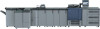
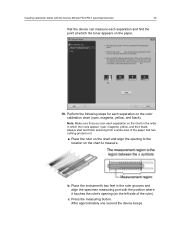
... the point at which the toner appears on the chart in the order in the ruler grooves and align the specimen measuring port with the Konica Minolta FD-5/FD-7 spectrophotometer 45 that has nothing printed on the left side of the ruler). Press the measuring button. Place the ruler on the chart...
... the point at which the toner appears on the chart in the order in the ruler grooves and align the specimen measuring port with the Konica Minolta FD-5/FD-7 spectrophotometer 45 that has nothing printed on the left side of the ruler). Press the measuring button. Place the ruler on the chart...


