Use and Care Guide
Page 15
... will automatically go into Keep Warm mode for the Drying Rack Accessory Kit. See "Assistance or Service" section to preheat. Place the magnetic door spacer Part Number 8010P146-60 over the plunger switch. "CNVT PASTRY" and "PREHEAT" will appear in oven more than one may be set time has elapsed the...
... will automatically go into Keep Warm mode for the Drying Rack Accessory Kit. See "Assistance or Service" section to preheat. Place the magnetic door spacer Part Number 8010P146-60 over the plunger switch. "CNVT PASTRY" and "PREHEAT" will appear in oven more than one may be set time has elapsed the...
Use and Care Guide
Page 25
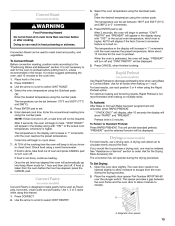
...your nearest KitchenAid designated service center. KitchenAid® Stainless Steel Cleaner and Polish (stainless steel models) Order Part Number 4396920 KitchenAid® Stainless Steel Wipes (stainless steel models) Order Part Number 8212510 If you need replacement parts If you use only factory specified parts. It ... call us to better respond to order replacement parts, we recommend that you need help us or your request. Call the KitchenAid Customer eXperience Center toll free: 1-800-422-1230. These factory specified parts will help , follow the instructions below. Our...
...your nearest KitchenAid designated service center. KitchenAid® Stainless Steel Cleaner and Polish (stainless steel models) Order Part Number 4396920 KitchenAid® Stainless Steel Wipes (stainless steel models) Order Part Number 8212510 If you need replacement parts If you use only factory specified parts. It ... call us to better respond to order replacement parts, we recommend that you need help us or your request. Call the KitchenAid Customer eXperience Center toll free: 1-800-422-1230. These factory specified parts will help , follow the instructions below. Our...
Use and Care Guide
Page 26
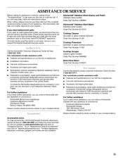
... Outside the 50 United States and Canada, this major appliance is used in the country in which it was purchased. KITCHENAID® GAS RANGE WARRANTY LIMITED WARRANTY For one year from the date of purchase, when this appliance is operated and maintained according to instructions ...when the major appliance is operated and maintained according to instructions attached to or furnished with the product, KitchenAid will pay for Factory Specified Parts for Factory Specified Parts and repair labor to correct defects in materials or workmanship. SECOND THROUGH FIFTH YEAR LIMITED WARRANTY ON ...
... Outside the 50 United States and Canada, this major appliance is used in the country in which it was purchased. KITCHENAID® GAS RANGE WARRANTY LIMITED WARRANTY For one year from the date of purchase, when this appliance is operated and maintained according to instructions ...when the major appliance is operated and maintained according to instructions attached to or furnished with the product, KitchenAid will pay for Factory Specified Parts for Factory Specified Parts and repair labor to correct defects in materials or workmanship. SECOND THROUGH FIFTH YEAR LIMITED WARRANTY ON ...
Installation Instructions
Page 3
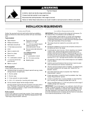
... floor anti-tip bracket must be killed. INSTALLATION REQUIREMENTS Tools and Parts Gather the required tools and parts before starting installation. Do not obstruct flow of burns or fire by installing a range hood or microwave hood combination that are included. ■ LP/Natural Gas Conversion Kit (taped near left rear leg, inside storage drawer...
... floor anti-tip bracket must be killed. INSTALLATION REQUIREMENTS Tools and Parts Gather the required tools and parts before starting installation. Do not obstruct flow of burns or fire by installing a range hood or microwave hood combination that are included. ■ LP/Natural Gas Conversion Kit (taped near left rear leg, inside storage drawer...
Installation Instructions
Page 4
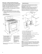
...8260;₄" (67.9 cm) depth to backguard standoffs. 29" (73.7 cm) depth with handle (KitchenAid models only) B. 35⁵⁄₈" (90.5 cm) cooktop height (minimum) with leveling legs... of the oven frame) G. IMPORTANT: If installing a range hood or microwave hood combination above the range, follow the range hood or microwave hood combination installation instructions for gas and electric installation I L J E F D G ... securing the range is not applicable, use the Standard for Mobile Home Construction and Safety, Title 24, HUD Part 280). clearance from wall M. E. 30" (76.2...
...8260;₄" (67.9 cm) depth to backguard standoffs. 29" (73.7 cm) depth with handle (KitchenAid models only) B. 35⁵⁄₈" (90.5 cm) cooktop height (minimum) with leveling legs... of the oven frame) G. IMPORTANT: If installing a range hood or microwave hood combination above the range, follow the range hood or microwave hood combination installation instructions for gas and electric installation I L J E F D G ... securing the range is not applicable, use the Standard for Mobile Home Construction and Safety, Title 24, HUD Part 280). clearance from wall M. E. 30" (76.2...
Installation Instructions
Page 7
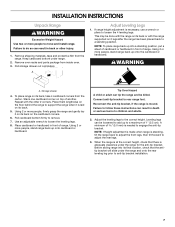
...correct height, check that the antitip bracket will slide under the range and onto the rear leveling leg prior to add up onto the cardboard or hardboard. Remove oven racks and parts package from the range. Pull storage drawer out completely. Place cardboard or hardboard in... death or serious burns to loosen the 4 leveling legs. Keep cardboard bottom under the range for the anti-tip bracket. If range height adjustment is moved. ...
...correct height, check that the antitip bracket will slide under the range and onto the rear leveling leg prior to add up onto the cardboard or hardboard. Remove oven racks and parts package from the range. Pull storage drawer out completely. Place cardboard or hardboard in... death or serious burns to loosen the 4 leveling legs. Keep cardboard bottom under the range for the anti-tip bracket. If range height adjustment is moved. ...
Installation Instructions
Page 9
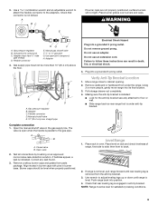
...extension cord. Making sure the anti-tip bracket is parallel to follow these instructions can result in death, fire, or electrical shock. 4. Level Range 1. Gas pressure regulator B. straight pipe Complete connection 1. A B A. If bubbles appear, a leak is not kinked. Correct any leak found. 3. ...parts package. Using 2 or more than 10" (25.4 cm) above the floor. Pull storage drawer out completely. 4. then front to adjust leveling legs up or down until rear leveling leg is under the range. If range is not level, pull range forward until range is engaged in the gas...
...extension cord. Making sure the anti-tip bracket is parallel to follow these instructions can result in death, fire, or electrical shock. 4. Level Range 1. Gas pressure regulator B. straight pipe Complete connection 1. A B A. If bubbles appear, a leak is not kinked. Correct any leak found. 3. ...parts package. Using 2 or more than 10" (25.4 cm) above the floor. Pull storage drawer out completely. 4. then front to adjust leveling legs up or down until rear leveling leg is under the range. If range is not level, pull range forward until range is engaged in the gas...
Installation Instructions
Page 11
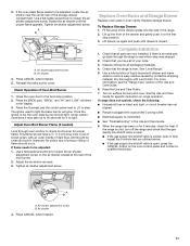
...located at the rear of the Use and Care Guide. 6. To Replace Storage Drawer: 1. Check that the gas supply line shutoff valve is open. ■ If the gas supply line shutoff valve is plugged into the rails in to remove waxy residue caused by protective shipping material. .... 8. Replace Oven Racks and Storage Drawer Replace oven racks in character. Complete Installation 1. If the range is level. Air shutter 4. If there is hot the oven bake burner should have all parts are now installed. Use a flat-blade screwdriver to check broil burner for heat. Air shutter adjustment ...
...located at the rear of the Use and Care Guide. 6. To Replace Storage Drawer: 1. Check that the gas supply line shutoff valve is open. ■ If the gas supply line shutoff valve is plugged into the rails in to remove waxy residue caused by protective shipping material. .... 8. Replace Oven Racks and Storage Drawer Replace oven racks in character. Complete Installation 1. If the range is level. Air shutter 4. If there is hot the oven bake burner should have all parts are now installed. Use a flat-blade screwdriver to check broil burner for heat. Air shutter adjustment ...
Installation Instructions
Page 14
...The small inner cone should have a very distinct blue flame ¼" to help hold the Natural gas orifice spud in plastic parts bag for the remaining burners. 9. The outer cone is very important. LP gas flames have to adjust the "LO" setting for each burner. Press nut driver down onto the ...Natural gas orifice spud and remove by turning it clockwise 4 or 5 turns. Broil burner orifice hood B. If ...
...The small inner cone should have a very distinct blue flame ¼" to help hold the Natural gas orifice spud in plastic parts bag for the remaining burners. 9. The outer cone is very important. LP gas flames have to adjust the "LO" setting for each burner. Press nut driver down onto the ...Natural gas orifice spud and remove by turning it clockwise 4 or 5 turns. Broil burner orifice hood B. If ...
Installation Instructions
Page 17
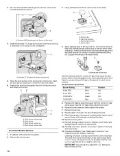
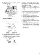
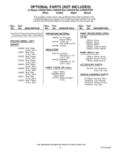
...Burner Rating Color Number 5,000 BTU Clear 110N 9,200 BTU Clear 150N 12,000 BTU Clear 170N 16,000 BTU Clear 195N 5. Place LP gas orifice spuds in the Use and Care Guide. 13. Burner base 4. Replace burner base and hand tighten the screws. 7. A A. See... the "Oven Door" section in plastic parts bag for each burner. Gas tube opening D. If installed, remove the burner grates. 2. Refer to adjust the "LO" setting for each burner location. Broil burner ...
...Burner Rating Color Number 5,000 BTU Clear 110N 9,200 BTU Clear 150N 12,000 BTU Clear 170N 16,000 BTU Clear 195N 5. Place LP gas orifice spuds in the Use and Care Guide. 13. Burner base 4. Replace burner base and hand tighten the screws. 7. A A. See... the "Oven Door" section in plastic parts bag for each burner. Gas tube opening D. If installed, remove the burner grates. 2. Refer to adjust the "LO" setting for each burner location. Broil burner ...

Parts Diagram
Page 1
... Models: KGRS205TWH0, KGRS205TSS0, KGRS205TBL0, KGRS205TBT0 (White) (S.Steel) (Black) (Biscuit) 30" GAS FREESTANDING SELF CLEAN RANGE SEALED BURNER CONVECTION Illus. Part No. No. Part No. No. No. Part No. W10206096 Rev.D DESCRIPTION 3 74008761 Spacer, Snap−In 4 Burner 74007411 (CTR) 74007698 (LF) 74009900 (RR & LR) 74007413 (RF) 5 Cooktop W10182781 Black W10182784 White W10160620 ...
... Models: KGRS205TWH0, KGRS205TSS0, KGRS205TBL0, KGRS205TBT0 (White) (S.Steel) (Black) (Biscuit) 30" GAS FREESTANDING SELF CLEAN RANGE SEALED BURNER CONVECTION Illus. Part No. No. Part No. No. No. Part No. W10206096 Rev.D DESCRIPTION 3 74008761 Spacer, Snap−In 4 Burner 74007411 (CTR) 74007698 (LF) 74009900 (RR & LR) 74007413 (RF) 5 Cooktop W10182781 Black W10182784 White W10160620 ...
Parts Diagram
Page 2
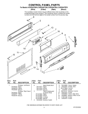
...;51 Bracket, Control 10 74003976 Screw 11 74009652 Cover, Main Wire 12 74008867 Bottom, Wire Cover 13 71001394 Screw 14 74002979 Screw 2 W10206096 CONTROL PANEL PARTS For Models: KGRS205TWH0, KGRS205TSS0, KGRS205TBL0, KGRS205TBT0 (White) (S.Steel) (Black) (Biscuit) Illus. DESCRIPTION 1 Endcap, Left Hand 74009023 Black 74009079 White 74009080 Biscuit Endcap... 74010577 Black 74010578 White 74010579 Biscuit 3 Panel, Backguard & Switch Assy W10218262 Black W10218265 White W10218264 S.Steel W10218263 Biscuit 4 74009098 Module, Spark Illus. Part No. No. Part No. No.
...;51 Bracket, Control 10 74003976 Screw 11 74009652 Cover, Main Wire 12 74008867 Bottom, Wire Cover 13 71001394 Screw 14 74002979 Screw 2 W10206096 CONTROL PANEL PARTS For Models: KGRS205TWH0, KGRS205TSS0, KGRS205TBL0, KGRS205TBT0 (White) (S.Steel) (Black) (Biscuit) Illus. DESCRIPTION 1 Endcap, Left Hand 74009023 Black 74009079 White 74009080 Biscuit Endcap... 74010577 Black 74010578 White 74010579 Biscuit 3 Panel, Backguard & Switch Assy W10218262 Black W10218265 White W10218264 S.Steel W10218263 Biscuit 4 74009098 Module, Spark Illus. Part No. No. Part No. No.
Parts Diagram
Page 4
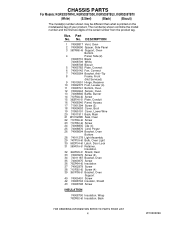
... 24 74008835 Clip (4) 25 74008876 Cord, Power 26 74008694 Bracket, Oven Bottom 28 74011278 Light Assembly 29 7407P103−60 Bulb, Oven Light 30 8002P104−60 Latch, Door Lock 31 3804F316−51 Retainer, Insulation 32 3604P409−51 Shield, Heat 33 74003976 Screw (2) 34 74011187 ...Support 40 74005401 Screw 42 74008704 Insulator, Shield 43 74008798 Screw INSULATION 74008700 Insulation, Wrap 7002P492−60 Insulation, Back 4 W10206096 CHASSIS PARTS For Models: KGRS205TWH0, KGRS205TSS0, KGRS205TBL0, KGRS205TBT0 (White) (S.Steel) (Black) (Biscuit) Illus.
... 24 74008835 Clip (4) 25 74008876 Cord, Power 26 74008694 Bracket, Oven Bottom 28 74011278 Light Assembly 29 7407P103−60 Bulb, Oven Light 30 8002P104−60 Latch, Door Lock 31 3804F316−51 Retainer, Insulation 32 3604P409−51 Shield, Heat 33 74003976 Screw (2) 34 74011187 ...Support 40 74005401 Screw 42 74008704 Insulator, Shield 43 74008798 Screw INSULATION 74008700 Insulation, Wrap 7002P492−60 Insulation, Back 4 W10206096 CHASSIS PARTS For Models: KGRS205TWH0, KGRS205TSS0, KGRS205TBL0, KGRS205TBT0 (White) (S.Steel) (Black) (Biscuit) Illus.
Parts Diagram
Page 5
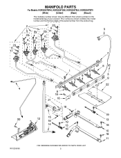
MANIFOLD PARTS For Models: KGRS205TWH0, KGRS205TSS0, KGRS205TBL0, KGRS205TBT0 (White) (S.Steel) (Black) (Biscuit) W10206096 5
MANIFOLD PARTS For Models: KGRS205TWH0, KGRS205TSS0, KGRS205TBL0, KGRS205TBT0 (White) (S.Steel) (Black) (Biscuit) W10206096 5
Parts Diagram
Page 6
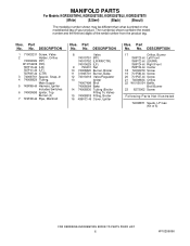
... Main Supply 5 7403P983−60 Harness, Igniter Includes Switches 6 74009958 Ignitor, Top Burner (4) 7 7513P499−60 Pipe, Manifold Illus. Part No. DESCRIPTION 17 Orifice, Burner 7509P123−60 Left Front 7509P122−60 (LR/RR) 7509P124−60 Right Front 7509P120−60 ...19 7101P282−60 Screw 20 7101P027−60 Screw 21 74008834 Orifice 22 W10156134 Baffle, Broil Burner 23 8273062 Screw Following Parts Not Illustrated 74008871 Spuds, LP Gas (Kit of 5) 6 W10206096 DESCRIPTION 8 Valve 74010751 (RF) 74010752 (LR/RR/CTR) 74010629 (LF) 9 790431 Nut...
... Main Supply 5 7403P983−60 Harness, Igniter Includes Switches 6 74009958 Ignitor, Top Burner (4) 7 7513P499−60 Pipe, Manifold Illus. Part No. DESCRIPTION 17 Orifice, Burner 7509P123−60 Left Front 7509P122−60 (LR/RR) 7509P124−60 Right Front 7509P120−60 ...19 7101P282−60 Screw 20 7101P027−60 Screw 21 74008834 Orifice 22 W10156134 Baffle, Broil Burner 23 8273062 Screw Following Parts Not Illustrated 74008871 Spuds, LP Gas (Kit of 5) 6 W10206096 DESCRIPTION 8 Valve 74010751 (RF) 74010752 (LR/RR/CTR) 74010629 (LF) 9 790431 Nut...
Parts Diagram
Page 10
...) Illus. DESCRIPTION Illus. No. Part No. No. DESCRIPTION Following Parts Not Illustrated SPLICING WIRES−−25FT. Part No. LENGTH 242828 Wire, Black 12 Ga. 150 c 242821 Wire, Blue 14 Ga. 150 c 242822 Wire, Brown 14 Ga. 150 c 242830 Wire, Brown 14 Ga. 200 c 242823 Wire, Green 14 Ga. 150 c 242824 Wire, Orange 14 Ga. 150 c 242825 Wire, Red...
...) Illus. DESCRIPTION Illus. No. Part No. No. DESCRIPTION Following Parts Not Illustrated SPLICING WIRES−−25FT. Part No. LENGTH 242828 Wire, Black 12 Ga. 150 c 242821 Wire, Blue 14 Ga. 150 c 242822 Wire, Brown 14 Ga. 150 c 242830 Wire, Brown 14 Ga. 200 c 242823 Wire, Green 14 Ga. 150 c 242824 Wire, Orange 14 Ga. 150 c 242825 Wire, Red...


