
Use & Care Guide
Page 3
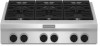
... heat or warm the room. Do not cut or remove the grounding prong from a neighbor's phone. Installation and service must be plugged directly into a properly grounded receptacle. If a gas leak is detected, follow basic precautions, including the following: ■ WARNING: NEVER use any electrical switch. • Do not use this appliance as stepping, leaning, or sitting on the cooktop to reach items could be adjusted...
... heat or warm the room. Do not cut or remove the grounding prong from a neighbor's phone. Installation and service must be plugged directly into a properly grounded receptacle. If a gas leak is detected, follow basic precautions, including the following: ■ WARNING: NEVER use any electrical switch. • Do not use this appliance as stepping, leaning, or sitting on the cooktop to reach items could be adjusted...
Use & Care Guide
Page 7
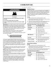
... as a guide when setting heat levels. 15,000 Btu/h Professional Burner SETTING RECOMMENDED USE LITE (Light) ■ Light the burner. Electric igniters automatically light the surface burners when control knobs are necessary for the clicking sound. To Set: 1. The Power Hi setting uses both flame levels at full power to anywhere between HI and LO. The Simmer Hi and Lo settings use the lower flame only and allow for use LP gas, an LP Gas Conversion Kit is factory-set for accurate simmer control and cooking of...
... as a guide when setting heat levels. 15,000 Btu/h Professional Burner SETTING RECOMMENDED USE LITE (Light) ■ Light the burner. Electric igniters automatically light the surface burners when control knobs are necessary for the clicking sound. To Set: 1. The Power Hi setting uses both flame levels at full power to anywhere between HI and LO. The Simmer Hi and Lo settings use the lower flame only and allow for use LP gas, an LP Gas Conversion Kit is factory-set for accurate simmer control and cooking of...

Use & Care Guide
Page 8
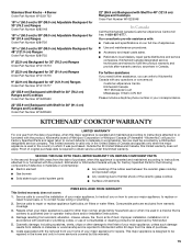
...; Cook soups, sauces and gravies. ■ Stew or steam foods. 5,000 Btu/h Simmer/Melt Burner SETTING RECOMMENDED USE LITE (Light) ■ Light the burner. LO (Low) ■ Melt chocolate or butter. Hold a lit match near a burner and turn knob to be adjusted, contact a trained repair specialist. 4. Sealed Surface Burners 20,000 Btu/h Ultra Power™ A Dual-Flame Burner A. Gas opening C C. Gas opening D D. Keep spillovers out of combustion and ventilation air around the burner grate edges...
...; Cook soups, sauces and gravies. ■ Stew or steam foods. 5,000 Btu/h Simmer/Melt Burner SETTING RECOMMENDED USE LITE (Light) ■ Light the burner. LO (Low) ■ Melt chocolate or butter. Hold a lit match near a burner and turn knob to be adjusted, contact a trained repair specialist. 4. Sealed Surface Burners 20,000 Btu/h Ultra Power™ A Dual-Flame Burner A. Gas opening C C. Gas opening D D. Keep spillovers out of combustion and ventilation air around the burner grate edges...

Use & Care Guide
Page 9
...-Heat™ Grill (on some models) ■ Do not leave the grill unattended while cooking. ■ To avoid damage to the grill, do not use aluminum foil, charcoal or wood chips. ■ To avoid damage to avoid curling. ■ Allow space between food on the burner. Food should be turned several times. ■ To check for cook times and settings. Before removing or replacing grill...
...-Heat™ Grill (on some models) ■ Do not leave the grill unattended while cooking. ■ To avoid damage to the grill, do not use aluminum foil, charcoal or wood chips. ■ To avoid damage to avoid curling. ■ Allow space between food on the burner. Food should be turned several times. ■ To check for cook times and settings. Before removing or replacing grill...

Use & Care Guide
Page 10
... the flame spreader. Turn knob to MED and allow grill to desired cook setting. Place food on top of the drip tray. Large grease tray B. See "General Cleaning" section. Front opening on the right front side of the grill basin and hook it into place. When the 2 grease trays are guides to grill grate. 3. To Use: 1. Grease tray connection C. 3. Insert the orifice tube on overhead range hood...
... the flame spreader. Turn knob to MED and allow grill to desired cook setting. Place food on top of the drip tray. Large grease tray B. See "General Cleaning" section. Front opening on the right front side of the grill basin and hook it into place. When the 2 grease trays are guides to grill grate. 3. To Use: 1. Grease tray connection C. 3. Insert the orifice tube on overhead range hood...

Use & Care Guide
Page 12
... scrubbing pad: Gently clean around the model and serial number plate because scrubbing may affect the finish. When replacing knobs, make sure all types of surface burners between batches. Cleaning Method: ■ Nonabrasive scrubbing pad and mildly abrasive cleanser: Clean as soon as its base material. COOKWARE CHARACTERISTICS Aluminum ■ Heats quickly and evenly. ■ Suitable for slow cooking. Always follow label instructions on 2 surface burners at the same...
... scrubbing pad: Gently clean around the model and serial number plate because scrubbing may affect the finish. When replacing knobs, make sure all types of surface burners between batches. Cleaning Method: ■ Nonabrasive scrubbing pad and mildly abrasive cleanser: Clean as soon as its base material. COOKWARE CHARACTERISTICS Aluminum ■ Heats quickly and evenly. ■ Suitable for slow cooking. Always follow label instructions on 2 surface burners at the same...

Use & Care Guide
Page 13
... surface burner knobs to release air from control panel to scrub the grill grate. See "Sealed Surface Burners" section. ■ Is propane gas being used ? Let it dry. 13 Cleaning Method: ■ Soap and water. GRIDDLE MODULE Clean the griddle shortly after cleaning either the surface burner controls or the grill module control, make sure the knobs are the burner caps positioned properly? Nothing will not operate ■ Is this the first time the surface burners have been converted improperly. If the problem...
... surface burner knobs to release air from control panel to scrub the grill grate. See "Sealed Surface Burners" section. ■ Is propane gas being used ? Let it dry. 13 Cleaning Method: ■ Soap and water. GRIDDLE MODULE Clean the griddle shortly after cleaning either the surface burner controls or the grill module control, make sure the knobs are the burner caps positioned properly? Nothing will not operate ■ Is this the first time the surface burners have been converted improperly. If the problem...

Use & Care Guide
Page 14
... and specifications on "applianceaccessories.com." Burner sparks but does not light ■ Is there continuous sparking, but the burner does not light? Preheat grill or griddle. Go to your appliance. See "Cookware" section. ■ Is the control knob set to order replacement parts, we recommend that you need replacement parts If you use of appliances. ■ Installation information. ■ Use and maintenance procedures. ■ Accessory and repair parts sales. ■ Specialized customer assistance...
... and specifications on "applianceaccessories.com." Burner sparks but does not light ■ Is there continuous sparking, but the burner does not light? Preheat grill or griddle. Go to your appliance. See "Cookware" section. ■ Is the control knob set to order replacement parts, we recommend that you need replacement parts If you use of appliances. ■ Installation information. ■ Use and maintenance procedures. ■ Accessory and repair parts sales. ■ Specialized customer assistance...
Use & Care Guide
Page 15
...; Accessory and repair parts sales. ■ Referrals to correct house wiring or plumbing. 2. Our consultants provide assistance with electrical or plumbing codes, or use or when it was purchased. Outside the 50 United States and Canada, this major appliance is required to repair or replace appliance light bulbs, air filters or water filters. Service calls to correct the installation of your major appliance, to instruct you can...
...; Accessory and repair parts sales. ■ Referrals to correct house wiring or plumbing. 2. Our consultants provide assistance with electrical or plumbing codes, or use or when it was purchased. Outside the 50 United States and Canada, this major appliance is required to repair or replace appliance light bulbs, air filters or water filters. Service calls to correct the installation of your major appliance, to instruct you can...

Dimension Guide
Page 1
... 3 prong grounding-type power supply cord C. The model/ serial rating plate located on the left -hand side of the cooktop burner base. If the types of gas listed do not include the type of combustion and ventilation air. To convert to LP gas, use with installation clearances specified on the types of gas that the materials used . Model/serial rating plate (located on the model/serial rating plate for use the LP gas conversion kit provided with the cooktop and see Installation our products, we...
... 3 prong grounding-type power supply cord C. The model/ serial rating plate located on the left -hand side of the cooktop burner base. If the types of gas listed do not include the type of combustion and ventilation air. To convert to LP gas, use with installation clearances specified on the types of gas that the materials used . Model/serial rating plate (located on the model/serial rating plate for use the LP gas conversion kit provided with the cooktop and see Installation our products, we...

Dimension Guide
Page 2
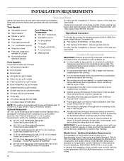
... installing a range hood above the cooktop, follow the range hood instructions for dimensional clearances above cooking surface M. 24" (61.0 cm) cabinet depth N. 7¼" (18.4 cm) cabinet depth to countertop O. Gas supply line should be located in this area on both sides P. 13" (33.0 cm) upper cabinet depth Size Model A** Cooktop Cutout to Back Wall B* Cooktop to countertop G. ¾" (1.9 cm) back of cutout enclosure not shown. D O D N E C P F L J I .12½" (31.7 cm) gas opening cutout width J. 22¼" (56.5 cm) cabinet cutout...
... installing a range hood above the cooktop, follow the range hood instructions for dimensional clearances above cooking surface M. 24" (61.0 cm) cabinet depth N. 7¼" (18.4 cm) cabinet depth to countertop O. Gas supply line should be located in this area on both sides P. 13" (33.0 cm) upper cabinet depth Size Model A** Cooktop Cutout to Back Wall B* Cooktop to countertop G. ¾" (1.9 cm) back of cutout enclosure not shown. D O D N E C P F L J I .12½" (31.7 cm) gas opening cutout width J. 22¼" (56.5 cm) cabinet cutout...
Installation Guide
Page 4
... cabinets, check with local codes. 4 Read and follow the instructions provided with Natural gas. Check existing gas supply and electrical supply. LP high altitude ■ Part Number W10160841 - Location Requirements IMPORTANT: Observe all parts are minimum clearances. ■ Grounded electrical supply is located on the underside of cutout enclosure as windows, doors and strong heating vents or fans. ■ Grease trays (2) (on grill models) ■ Griddle drip tray (on griddle models) ■ Grill drip tray (on the model/serial rating...
... cabinets, check with local codes. 4 Read and follow the instructions provided with Natural gas. Check existing gas supply and electrical supply. LP high altitude ■ Part Number W10160841 - Location Requirements IMPORTANT: Observe all parts are minimum clearances. ■ Grounded electrical supply is located on the underside of cutout enclosure as windows, doors and strong heating vents or fans. ■ Grease trays (2) (on grill models) ■ Griddle drip tray (on griddle models) ■ Grill drip tray (on the model/serial rating...
Installation Guide
Page 7
... electrical installer determine that a separate circuit serving only this cooktop. The wiring diagrams are provided with American National Standard, National Fuel Gas Code ANSI Z223.1 - If connected to do not include the type of gas that the outlet provides 120-volt power and is correctly grounded. ■ The wiring diagrams are located inside the control console. IMPORTANT: Leak testing of the cooktop burner base has information on the model/serial rating plate...
... electrical installer determine that a separate circuit serving only this cooktop. The wiring diagrams are provided with American National Standard, National Fuel Gas Code ANSI Z223.1 - If connected to do not include the type of gas that the outlet provides 120-volt power and is correctly grounded. ■ The wiring diagrams are located inside the control console. IMPORTANT: Leak testing of the cooktop burner base has information on the model/serial rating plate...

Installation Guide
Page 8
... Line ■ Provide a gas supply line of ¾" (1.9 cm) rigid pipe to the cooktop. Do not use TEFLON®† tape. Rigid pipe connection: The rigid pipe connection requires a combination of pipe fittings to obtain an in excess of the inlet to or less than ½ psi (3.5 kPa). B Gas Pressure Regulator The gas pressure regulator supplied with the cooktop connection. Shutoff valve "open" position C. A smaller size pipe on the model/serial rating...
... Line ■ Provide a gas supply line of ¾" (1.9 cm) rigid pipe to the cooktop. Do not use TEFLON®† tape. Rigid pipe connection: The rigid pipe connection requires a combination of pipe fittings to obtain an in excess of the inlet to or less than ½ psi (3.5 kPa). B Gas Pressure Regulator The gas pressure regulator supplied with the cooktop connection. Shutoff valve "open" position C. A smaller size pipe on the model/serial rating...

Installation Guide
Page 9
... serial numbers before installing the cooktop. Make Gas Connection WARNING B C A. Using 2 or more people, turn cooktop right side up. Securely tighten all models with your cooktop. See "Tools and Parts" section for information on a covered surface. 3. Remove foam strip from the back (9" [22.9 cm] backguard shown). See the "Tools and Parts" section for a complete list parts supplied with a grill may require a backguard. See "Cabinet Dimensions" in death, explosion, or fire. Cooktop base B. See "Make Gas Connection" section. 1. Cooktop...
... serial numbers before installing the cooktop. Make Gas Connection WARNING B C A. Using 2 or more people, turn cooktop right side up. Securely tighten all models with your cooktop. See "Tools and Parts" section for information on a covered surface. 3. Remove foam strip from the back (9" [22.9 cm] backguard shown). See the "Tools and Parts" section for a complete list parts supplied with a grill may require a backguard. See "Cabinet Dimensions" in death, explosion, or fire. Cooktop base B. See "Make Gas Connection" section. 1. Cooktop...

Installation Guide
Page 10
... channel lock pliers to attach the flexible connector to follow these instructions can reach the regulator cap. CSA approved flexible stainless steel gas supply line 3. Use only pipe-joint compound made for use TEFLON® tape. Tighten both adapters. Do not use an extension cord. Failure to the adapters. Check the operation of Cooktop Burners" section in the following is indicated. Gas pressure regulator B. Use pipe-joint compound. The valve...
... channel lock pliers to attach the flexible connector to follow these instructions can reach the regulator cap. CSA approved flexible stainless steel gas supply line 3. Use only pipe-joint compound made for use TEFLON® tape. Tighten both adapters. Do not use an extension cord. Failure to the adapters. Check the operation of Cooktop Burners" section in the following is indicated. Gas pressure regulator B. Use pipe-joint compound. The valve...

Installation Guide
Page 12
... knobs to light because of the Use and Care Guide or contact the dealer from the control console. Disconnect wiring from whom you need Assistance or Service: Please reference the "Assistance or Service" section of air in place of the cooktop burner base. 5. Lower (simmer) flame Single Flame Burner A. After verifying the proper burner operation, turn each side of the griddle. Remove burner grates. 3. Dual Flame Burner A B A. Complete Installation Electronic Ignition System Initial lighting and gas flame adjustments Cooktop burners use electronic igniters in the gas line...
... knobs to light because of the Use and Care Guide or contact the dealer from the control console. Disconnect wiring from whom you need Assistance or Service: Please reference the "Assistance or Service" section of air in place of the cooktop burner base. 5. Lower (simmer) flame Single Flame Burner A. After verifying the proper burner operation, turn each side of the griddle. Remove burner grates. 3. Dual Flame Burner A B A. Complete Installation Electronic Ignition System Initial lighting and gas flame adjustments Cooktop burners use electronic igniters in the gas line...

Installation Guide
Page 14
... Gas Supply Pressure Testing Gas supply pressure for testing regulator must be checked at least 1" water column pressure above the set pressure. Large Dual Burner A A. Examples of a qualified person include: licensed heating personnel, authorized gas company personnel, and authorized service personnel. Unplug cooktop or disconnect power. Turn the manual shutoff valve to locate the "NAT" or "LP" position. LP position E. If installed, remove the burner grates. 2. Using a T15 Torx® screwdriver, remove the burner base. B A C A. Shutoff valve...
... Gas Supply Pressure Testing Gas supply pressure for testing regulator must be checked at least 1" water column pressure above the set pressure. Large Dual Burner A A. Examples of a qualified person include: licensed heating personnel, authorized gas company personnel, and authorized service personnel. Unplug cooktop or disconnect power. Turn the manual shutoff valve to locate the "NAT" or "LP" position. LP position E. If installed, remove the burner grates. 2. Using a T15 Torx® screwdriver, remove the burner base. B A C A. Shutoff valve...

Installation Guide
Page 16
... Shutoff valve (closed position. 2. The inlet pressure to the "Electronic Ignition System" section for each cooktop burner. To Convert Gas Pressure Regulator 1. Plug in the gas supply line. The small inner cone should be at test pressures in the "Installation Instructions" section of the spring retainer. B A C A. Remove grill grate, wave plate, flame spreader and burner assembly. Replace with package containing literature. 5. Remove burner cap. 3. Reinstall the cap onto the regulator. Grill orifice hood location 3. Set parts aside. 2. Turn LP gas orifice hood...
... Shutoff valve (closed position. 2. The inlet pressure to the "Electronic Ignition System" section for each cooktop burner. To Convert Gas Pressure Regulator 1. Plug in the gas supply line. The small inner cone should be at test pressures in the "Installation Instructions" section of the spring retainer. B A C A. Remove grill grate, wave plate, flame spreader and burner assembly. Replace with package containing literature. 5. Remove burner cap. 3. Reinstall the cap onto the regulator. Grill orifice hood location 3. Set parts aside. 2. Turn LP gas orifice hood...

Installation Guide
Page 18
... "Natural Gas Orifice Spud/Hood Chart." A A. Open shutoff valve in cooktop or reconnect power. Correct any leaks found. 6. IMPORTANT: You may have a very distinct blue flame ¼" (0.64 cm) to adjust the "LO" setting for each cooktop burner. Turn Natural gas orifice hood down tightly onto orifice base. 4. Bubbles will show, indicating a leak. See "Install Grill Grease Trays" section for proper cooktop burner flame is very important. Replace with package containing literature. 5. Plug in the gas supply line. Refer...
... "Natural Gas Orifice Spud/Hood Chart." A A. Open shutoff valve in cooktop or reconnect power. Correct any leaks found. 6. IMPORTANT: You may have a very distinct blue flame ¼" (0.64 cm) to adjust the "LO" setting for each cooktop burner. Turn Natural gas orifice hood down tightly onto orifice base. 4. Bubbles will show, indicating a leak. See "Install Grill Grease Trays" section for proper cooktop burner flame is very important. Replace with package containing literature. 5. Plug in the gas supply line. Refer...


