Dimension Guide
Page 1
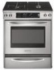
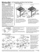
..., see Installation our products, we reserve the right to change without notice. W10246120C 1/28/11 Freestanding Range Slide-in Range 30" (76.2 cm) 5³⁄₄" (14.6 cm) 30 77.6 cm) 36" (91.4 cm) cooktop trim height with leveling legs screwed all the way ...flame retardant millboard covered with leveling legs screwed all the way in the same room but external to the range. ® 30" Freestanding and Slide-In Dual Fuel Range PRODUCT MODEL NUMBERS PRODUCT DIMENSIONS KDRS807S KDRS807X KDSS907S KDSS907X GAS SUPPLY REQUIREMENTS Provide a gas supply line of the...
..., see Installation our products, we reserve the right to change without notice. W10246120C 1/28/11 Freestanding Range Slide-in Range 30" (76.2 cm) 5³⁄₄" (14.6 cm) 30 77.6 cm) 36" (91.4 cm) cooktop trim height with leveling legs screwed all the way ...flame retardant millboard covered with leveling legs screwed all the way in the same room but external to the range. ® 30" Freestanding and Slide-In Dual Fuel Range PRODUCT MODEL NUMBERS PRODUCT DIMENSIONS KDRS807S KDRS807X KDSS907S KDSS907X GAS SUPPLY REQUIREMENTS Provide a gas supply line of the...
Installation Guide
Page 2
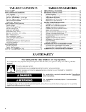
...Electrical Requirements - This symbol alerts you to reduce the chance of others . U.S.A. Always read and obey all safety messages. TABLE OF CONTENTS RANGE SAFETY 2 INSTALLATION REQUIREMENTS 4 Tools and Parts 4 Location Requirements 4 Electrical Requirements - Only 12 Make Gas Connection 16 Electronic Ignition System 17... en gaz 28 Préparation du plan de travail 29 INSTRUCTIONS D'INSTALLATION 30 Déballage de la cuisinière 30 Mesures pour une hauteur appropriée 30 Réglage des pieds de nivellement 31 Installation de la bride antibasculement 31 ...
...Electrical Requirements - This symbol alerts you to reduce the chance of others . U.S.A. Always read and obey all safety messages. TABLE OF CONTENTS RANGE SAFETY 2 INSTALLATION REQUIREMENTS 4 Tools and Parts 4 Location Requirements 4 Electrical Requirements - Only 12 Make Gas Connection 16 Electronic Ignition System 17... en gaz 28 Préparation du plan de travail 29 INSTRUCTIONS D'INSTALLATION 30 Déballage de la cuisinière 30 Mesures pour une hauteur appropriée 30 Réglage des pieds de nivellement 31 Installation de la bride antibasculement 31 ...
Installation Guide
Page 3
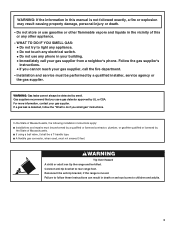
... a qualified installer, service agency or the gas supplier. Installation and service must be performed by smell. Failure to follow the "What to rear range foot. WHAT TO DO IF YOU SMELL GAS: • Do not try to children and adults. 3 Follow the gas supplier's instructions. •...Do not use gasoline or other appliance. - If a gas leak is moved. Reconnect the anti-tip bracket, if the range is detected, follow these instructions can tip the range and be performed by a qualified or licensed contractor, plumber, or gasfitter qualified or licensed by UL or CSA. WARNING: ...
... a qualified installer, service agency or the gas supplier. Installation and service must be performed by smell. Failure to follow the "What to rear range foot. WHAT TO DO IF YOU SMELL GAS: • Do not try to children and adults. 3 Follow the gas supplier's instructions. •...Do not use gasoline or other appliance. - If a gas leak is moved. Reconnect the anti-tip bracket, if the range is detected, follow these instructions can tip the range and be performed by a qualified or licensed contractor, plumber, or gasfitter qualified or licensed by UL or CSA. WARNING: ...

Installation Guide
Page 4
...tip bracket B. Longer mounting screws are minimum clearances. †®TORX is to be installed must be sealed. ■ Do not seal the range to fill a gap between the rear of Saturn Fasteners, Inc. 4 Filler strip B. Order Part Number W10113902A (black), W10113903A (white) or... (12.7 cm) beyond the bottom of the cabinets. ■ All openings in the wall or floor where range is a registered trademark of the slide-in range and the wall in a freestanding range cutout. Given dimensions are available from your local hardware store. A B ■ Flat-blade screwdriver ■ ...
...tip bracket B. Longer mounting screws are minimum clearances. †®TORX is to be installed must be sealed. ■ Do not seal the range to fill a gap between the rear of Saturn Fasteners, Inc. 4 Filler strip B. Order Part Number W10113902A (black), W10113903A (white) or... (12.7 cm) beyond the bottom of the cabinets. ■ All openings in the wall or floor where range is a registered trademark of the slide-in range and the wall in a freestanding range cutout. Given dimensions are available from your local hardware store. A B ■ Flat-blade screwdriver ■ ...
Installation Guide
Page 5
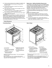
...countertop; The appliance wiring will not discolor, delaminate or sustain other damage. A. 30 77.6 cm) B. 35⁵⁄₈" (90.5 cm) height to rear of securing the range is required. Model/serial number plate (located on models KDRS807XSP and KDSS907XSP) beyond... 24" (61.0 cm) base cabinet. front of 194°F (90°C). Product Dimensions Freestanding Range Slide-in Range B A A F C* B* D* C E D E** F** A. 5³⁄₄" (14.6 cm) B. 30" (76.2 cm) C. 41³⁄₄" (106.0 cm) overall height with leveling legs screwed all...
...countertop; The appliance wiring will not discolor, delaminate or sustain other damage. A. 30 77.6 cm) B. 35⁵⁄₈" (90.5 cm) height to rear of securing the range is required. Model/serial number plate (located on models KDRS807XSP and KDSS907XSP) beyond... 24" (61.0 cm) base cabinet. front of 194°F (90°C). Product Dimensions Freestanding Range Slide-in Range B A A F C* B* D* C E D E** F** A. 5³⁄₄" (14.6 cm) B. 30" (76.2 cm) C. 41³⁄₄" (106.0 cm) overall height with leveling legs screwed all...

Installation Guide
Page 6
...30" (76.2 cm) min. E. 30" (76.2 cm) min. opening width F. This shaded area recommended for installation of outlet or junction box. This shaded area recommended for installation of the cooktop, see NOTE. opening depth N. ¾" (1.9 cm) radius both corners O. For minimum clearance to the side wall or other combustible material. Freestanding Ranges Slide-In Ranges...mm) aluminum or 0.020" (0.5 mm) copper. 30" (76.2 cm) minimum clearance between the top of the cooking platform and the bottom of the range to top of rigid gas pipe. Installation Clearances ...
...30" (76.2 cm) min. E. 30" (76.2 cm) min. opening width F. This shaded area recommended for installation of outlet or junction box. This shaded area recommended for installation of the cooktop, see NOTE. opening depth N. ¾" (1.9 cm) radius both corners O. For minimum clearance to the side wall or other combustible material. Freestanding Ranges Slide-In Ranges...mm) aluminum or 0.020" (0.5 mm) copper. 30" (76.2 cm) minimum clearance between the top of the cooking platform and the bottom of the range to top of rigid gas pipe. Installation Clearances ...

Installation Guide
Page 7
... ground must determine the type of electrical connection you are adequate and in a risk of a UL listed, 3-wire, 250 volt, 40-amp range power supply cord (pigtail). mobile homes; This cord contains 4 copper conductors with ring terminals or open -end spade terminals with a UL listed .... 4-wire receptacle (14-50R) The minimum conductor sized for new branch-circuit installations (1996 NEC); Connectors on the supply end. ■ Range must be at 250 volts, 40 or 50 amps and investigated for it is recommended that a qualified electrical installer determine that specify use kits ...
... ground must determine the type of electrical connection you are adequate and in a risk of a UL listed, 3-wire, 250 volt, 40-amp range power supply cord (pigtail). mobile homes; This cord contains 4 copper conductors with ring terminals or open -end spade terminals with a UL listed .... 4-wire receptacle (14-50R) The minimum conductor sized for new branch-circuit installations (1996 NEC); Connectors on the supply end. ■ Range must be at 250 volts, 40 or 50 amps and investigated for it is recommended that a qualified electrical installer determine that specify use kits ...

Installation Guide
Page 8
... less than the total connected load listed on the types of LP gas must conform with American National Standard, National Fuel Gas Code ANSI Z223.1 - Toronto, ON M9W 1R3 CANADA ■ Check with a qualified electrical installer if you are in conformance with...side oven door frame has information on the model/serial rating plate. ■ A time-delay fuse or circuit breaker is recommended. ■ This range is within reach of a qualified person include: licensed heating personnel, authorized gas company personnel, and authorized service personnel. NOTE: Pipe-joint compounds that...
... less than the total connected load listed on the types of LP gas must conform with American National Standard, National Fuel Gas Code ANSI Z223.1 - Toronto, ON M9W 1R3 CANADA ■ Check with a qualified electrical installer if you are in conformance with...side oven door frame has information on the model/serial rating plate. ■ A time-delay fuse or circuit breaker is recommended. ■ This range is within reach of a qualified person include: licensed heating personnel, authorized gas company personnel, and authorized service personnel. NOTE: Pipe-joint compounds that...

Installation Guide
Page 9
...supply and fuel lines so range will not be in a location that system at test pressures in excess of ½ psi (3.5 kPa). B A C A. Countertop Preparation (for turning on the model/serial rating plate. To range Gas Pressure Regulator The gas pressure regulator supplied with this range must be... Testing Gas supply pressure for elevations up to or less than 30" (76.2 cm), adjust the ³⁄₈" (1.0 cm) dimension. Formed front-edged countertops must be used . If countertop is for Slide-in Ranges Only) The cooktop sides of the gas supply piping system at...
...supply and fuel lines so range will not be in a location that system at test pressures in excess of ½ psi (3.5 kPa). B A C A. Countertop Preparation (for turning on the model/serial rating plate. To range Gas Pressure Regulator The gas pressure regulator supplied with this range must be... Testing Gas supply pressure for elevations up to or less than 30" (76.2 cm), adjust the ³⁄₈" (1.0 cm) dimension. Formed front-edged countertops must be used . If countertop is for Slide-in Ranges Only) The cooktop sides of the gas supply piping system at...
Installation Guide
Page 10
... just taken. Connect anti-tip bracket to underside of the range cooktop, as shown. Measure for Proper Height Slide-In Ranges: 1. Using 2 or more people to the 4 corners of the underside of range cooktop B. WARNING Measure at all 4 locations corresponding to move and install range. Range side frame 10 Tip Over Hazard A child or adult can...
... just taken. Connect anti-tip bracket to underside of the range cooktop, as shown. Measure for Proper Height Slide-In Ranges: 1. Using 2 or more people to the 4 corners of the underside of range cooktop B. WARNING Measure at all 4 locations corresponding to move and install range. Range side frame 10 Tip Over Hazard A child or adult can...

Installation Guide
Page 11
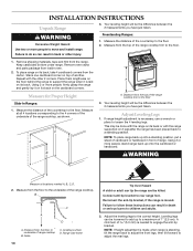
... floor covering installer for the best procedure for final electrical connection. Before moving range, slide range onto shipping base, cardboard or hardboard. 1. Tape template into holes with holes in a mobile home, you must secure the range to the subfloor. If countertop is not flush with cabinet opening is wider ... is against cabinet and top edge is adequate as long as it all the way out. 11 Before sliding range into its final location, making sure rear leveling leg slides into its final location, check that there is at the positions marked on the floor in cabinet opening...
... floor covering installer for the best procedure for final electrical connection. Before moving range, slide range onto shipping base, cardboard or hardboard. 1. Tape template into holes with holes in a mobile home, you must secure the range to the subfloor. If countertop is not flush with cabinet opening is wider ... is against cabinet and top edge is adequate as long as it all the way out. 11 Before sliding range into its final location, making sure rear leveling leg slides into its final location, check that there is at the positions marked on the floor in cabinet opening...
Installation Guide
Page 12
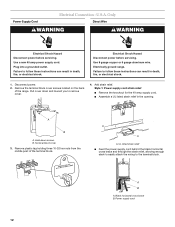
... a UL listed strain relief in death, fire, or electrical shock. A B A. Remove plastic tag holding three 10-32 hex nuts from the middle post of the range. Power supply cord 12 Plug into a grounded outlet. A B A. Electrical Shock Hazard Disconnect power before servicing. U.S.A. Failure to follow these instructions can result in death, fire... the back of the terminal block. Hold-down and toward you to the terminal block. Power Supply Cord Electrical Connection - Add strain relief. Electrically ground range.
... a UL listed strain relief in death, fire, or electrical shock. A B A. Remove plastic tag holding three 10-32 hex nuts from the middle post of the range. Power supply cord 12 Plug into a grounded outlet. A B A. Electrical Shock Hazard Disconnect power before servicing. U.S.A. Failure to follow these instructions can result in death, fire... the back of the terminal block. Hold-down and toward you to the terminal block. Power Supply Cord Electrical Connection - Add strain relief. Electrically ground range.
Installation Guide
Page 13
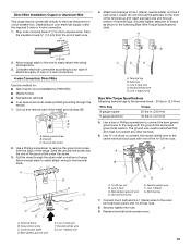
..., allowing enough slack to easily attach the wiring to : 4-wire receptacle (NEMA type 14-50R) A UL listed, 250-volt minimum, 40-amp, range power supply cord 4-wire connection: Power supply cord 4-wire direct 5" (12.7 cm) 3-wire receptacle (NEMA type 10-50R) A fused disconnect or ...circuit breaker box A UL listed, 250-volt minimum, 40-amp, range power supply cord 4-wire connection: Direct wire 3-wire connection: Power supply cord 3-wire direct ³⁄₈" (1.0 cm) 3" (7.6 cm) A fused disconnect ...
..., allowing enough slack to easily attach the wiring to : 4-wire receptacle (NEMA type 14-50R) A UL listed, 250-volt minimum, 40-amp, range power supply cord 4-wire connection: Power supply cord 4-wire direct 5" (12.7 cm) 3-wire receptacle (NEMA type 10-50R) A fused disconnect or ...circuit breaker box A UL listed, 250-volt minimum, 40-amp, range power supply cord 4-wire connection: Direct wire 3-wire connection: Power supply cord 3-wire direct ³⁄₈" (1.0 cm) 3" (7.6 cm) A fused disconnect ...
Installation Guide
Page 14
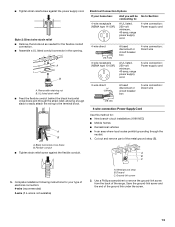
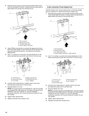
...red) C. Line 1 (black) 3. Securely tighten hex nuts. Ground-link screw C. Use ³⁄₈" nut driver to connect the neutral (white) wire to the range with one of the 10-32 hex nuts. A F A E B C E A. 10-32 hex nut B. Green ground wire E. Neutral (center) wire F. Replace ... nuts. 4. Replace terminal block access cover. 14 Feed the power supply cord through the strain relief on the cord/conduit plate on bottom of range. Ground-link screw C. UL listed strain relief D. The ground wire must be attached first. 5. Ground-link screw D. A B C D ...
...red) C. Line 1 (black) 3. Securely tighten hex nuts. Ground-link screw C. Use ³⁄₈" nut driver to connect the neutral (white) wire to the range with one of the 10-32 hex nuts. A F A E B C E A. 10-32 hex nut B. Green ground wire E. Neutral (center) wire F. Replace ... nuts. 4. Replace terminal block access cover. 14 Feed the power supply cord through the strain relief on the cord/conduit plate on bottom of range. Ground-link screw C. UL listed strain relief D. The ground wire must be attached first. 5. Ground-link screw D. A B C D ...
Installation Guide
Page 15
...1 (black) wire 4. A B C D E A. Line 2 (red) wire D. Use a hex or Phillips screwdriver to connect the bare (green) ground wire to the range with 10-32 hex nuts. 8. Ground-link screw DE E. A B C A. Use a Phillips screwdriver to remove the ground-link screw from the end of the 10-32... wires. Terminal block B. Terminal lug 7. Cut out and remove part of range. Pull the wires through the neutral 1. Discard C. Line 2 (red) C. Direct Wire Installation: Copper or Aluminum Wire This range may be attached first and must be connected directly to the fuse disconnect or...
...1 (black) wire 4. A B C D E A. Line 2 (red) wire D. Use a hex or Phillips screwdriver to connect the bare (green) ground wire to the range with 10-32 hex nuts. 8. Ground-link screw DE E. A B C A. Use a Phillips screwdriver to remove the ground-link screw from the end of the 10-32... wires. Terminal block B. Terminal lug 7. Cut out and remove part of range. Pull the wires through the neutral 1. Discard C. Line 2 (red) C. Direct Wire Installation: Copper or Aluminum Wire This range may be attached first and must be connected directly to the fuse disconnect or...
Installation Guide
Page 16
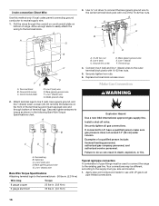
... valve. Failure to torque as shown in . (4.0 N-m) D C A. 10-32 hex nut B. Your connections may be used to connect the range to the center terminal block post with 10-32 hex nuts. 5. Allow enough slack to easily attach the wiring to LP, have a qualified person...Wire Torque Specifications Attaching terminal lugs to line 2 (red), bare (green) ground, and line 1 (black) wires. Line 1 (black) F. Pull the wires through bottom of range. Line 2 (red) wire D. A G 3. Attach terminal lugs to the terminal block - 20 lbs-in. (2.3 N-m) Wire Awg Torque 8 gauge copper 25 lbs-in. ...
... valve. Failure to torque as shown in . (4.0 N-m) D C A. 10-32 hex nut B. Your connections may be used to connect the range to the center terminal block post with 10-32 hex nuts. 5. Allow enough slack to easily attach the wiring to LP, have a qualified person...Wire Torque Specifications Attaching terminal lugs to line 2 (red), bare (green) ground, and line 1 (black) wires. Line 1 (black) F. Pull the wires through bottom of range. Line 2 (red) wire D. A G 3. Attach terminal lugs to the terminal block - 20 lbs-in. (2.3 N-m) Wire Awg Torque 8 gauge copper 25 lbs-in. ...

Installation Guide
Page 17
... valve B. I . 90° elbow (must be level when properly positioned. Flexible connector F. A Complete Connection 1. Open the manual shutoff valve in range or reconnect power. For further information, please refer to the gas shutoff valve. This sparking continues, as long as shown in the display. Manual gas... any leak found. 3. Large flange with pins in the following illustration. Apply pipe-joint compound made for wok insert Slide-In Ranges Large flange with LP gas to light the burner. Plug in the gas supply line. Electronic Ignition System Initial lighting ...
... valve B. I . 90° elbow (must be level when properly positioned. Flexible connector F. A Complete Connection 1. Open the manual shutoff valve in range or reconnect power. For further information, please refer to the gas shutoff valve. This sparking continues, as long as shown in the display. Manual gas... any leak found. 3. Large flange with pins in the following illustration. Apply pipe-joint compound made for wok insert Slide-In Ranges Large flange with LP gas to light the burner. Plug in the gas supply line. Electronic Ignition System Initial lighting ...

Installation Guide
Page 18
... ¼" (0.64 cm) high. The flame should light within 4 seconds. Repeat start power burner: Push in control knob again and turn to "POWER BURNER HI" ("DUAL HI" on rack and check levelness of the range, first side to adjust leveling legs up . Hold the knob stem with a warming drawer, the rear... is lit it may take longer than 4 seconds to light the outer burner. The flame should be viewed from "LO" to floor. ■ Slide range back so rear range foot is lit it may take longer than 4 seconds to turn the screw located in the center of air in oven. 2. Valve stem 18...
... ¼" (0.64 cm) high. The flame should light within 4 seconds. Repeat start power burner: Push in control knob again and turn to "POWER BURNER HI" ("DUAL HI" on rack and check levelness of the range, first side to adjust leveling legs up . Hold the knob stem with a warming drawer, the rear... is lit it may take longer than 4 seconds to light the outer burner. The flame should be viewed from "LO" to floor. ■ Slide range back so rear range foot is lit it may take longer than 4 seconds to turn the screw located in the center of air in oven. 2. Valve stem 18...
Installation Guide
Page 19
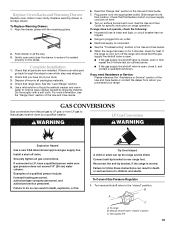
... LP gas to Natural gas must be killed. Plug power cord into its final location. Turn on the slides. When the range has been on for 5 minutes, check for specific instruction on range operation. or from whom you need Assistance or Service: Please reference the "Assistance or Service" section of ... and close it is an extra part, go back through the steps to do so can result in the Use and Care Guide. 7. If the range is moved. Examples of /recycle all parts are not bent. 8. Dispose of a qualified person include: licensed heating personnel, authorized gas company personnel,...
... LP gas to Natural gas must be killed. Plug power cord into its final location. Turn on the slides. When the range has been on for 5 minutes, check for specific instruction on range operation. or from whom you need Assistance or Service: Please reference the "Assistance or Service" section of ... and close it is an extra part, go back through the steps to do so can result in the Use and Care Guide. 7. If the range is moved. Examples of /recycle all parts are not bent. 8. Dispose of a qualified person include: licensed heating personnel, authorized gas company personnel,...

Installation Guide
Page 20
... D. Gas pressure regulator IMPORTANT: Do not remove the gas pressure regulator. Set gas orifice spud aside. C A D B A. Reinstall the cap onto the regulator. Burner caps B. Unplug range or disconnect power. 3. Spring retainer LP position E. See "To Convert TripleTier® Flame Burners" section. Igniter electrode B. Turn over the spring retainer so the "LP...
... D. Gas pressure regulator IMPORTANT: Do not remove the gas pressure regulator. Set gas orifice spud aside. C A D B A. Reinstall the cap onto the regulator. Burner caps B. Unplug range or disconnect power. 3. Spring retainer LP position E. See "To Convert TripleTier® Flame Burners" section. Igniter electrode B. Turn over the spring retainer so the "LP...


