Dimension Guide
Page 1
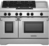
... CFR, Part 3280 (formerly the Federal Standard for use with local codes. 30", 36", and 48" Professional Dual Fuel Convection Ranges PRODUCT MODEL NUMBERS KDRS407VSS KDRS462VSS KDRS463VSS KDRS467VSS KDRS483VSS KDRU707VSS GAS REQUIREMENTS KDRU763VSS KDRU767VSS KDRU783VSS Type of Gas Natural Gas: This range is installed in a mobile home, it must be secured to the floor during transit. The...
... CFR, Part 3280 (formerly the Federal Standard for use with local codes. 30", 36", and 48" Professional Dual Fuel Convection Ranges PRODUCT MODEL NUMBERS KDRS407VSS KDRS462VSS KDRS463VSS KDRS467VSS KDRS483VSS KDRU707VSS GAS REQUIREMENTS KDRU763VSS KDRU767VSS KDRU783VSS Type of Gas Natural Gas: This range is installed in a mobile home, it must be secured to the floor during transit. The...

Dimension Guide
Page 2
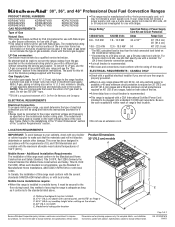
... policy includes a continuous commitment to improve Dimensions are for all models. Ref. 36" (91.4 cm) models A B IMPORTANT: If installing a range hood above the range, follow the range hood installation instructions for dimension planning purposes only, and the locations... with product. W10349767A 1/04/11 C D ** B C E D O*** F A F H I J Electrical installation K area* E I G L N M J Gas installation area 48" (121.9 cm) models NOTE: The following illustration is required for 25" (64 cm) countertop depth, 24" (61 cm) base cabinet depth and 36" (91.4 cm) countertop height...
... policy includes a continuous commitment to improve Dimensions are for all models. Ref. 36" (91.4 cm) models A B IMPORTANT: If installing a range hood above the range, follow the range hood installation instructions for dimension planning purposes only, and the locations... with product. W10349767A 1/04/11 C D ** B C E D O*** F A F H I J Electrical installation K area* E I G L N M J Gas installation area 48" (121.9 cm) models NOTE: The following illustration is required for 25" (64 cm) countertop depth, 24" (61 cm) base cabinet depth and 36" (91.4 cm) countertop height...

Installation Guide
Page 4
...;®TORX is moved. Reconnect the anti-tip bracket, if the range is a registered trademark of flooring may require longer screws to anchor bracket to subfloor. A UL listed 40 amp power supply cord kit ■ 48" (121.9 cm) models - Tools needed ■ Burner grates ■ Burner heads and ...Parts needed ■ Power supply cord kit: ■ 30" (76.2 cm) and 36" (91.4 cm) models - A UL listed 50 amp power supply cord kit marked for 48" (121.9 cm) Ranges Order Part Number W10115777 4 See "Cabinet Dimensions" in death or serious burns to children and adults. Read and ...
...;®TORX is moved. Reconnect the anti-tip bracket, if the range is a registered trademark of flooring may require longer screws to anchor bracket to subfloor. A UL listed 40 amp power supply cord kit ■ 48" (121.9 cm) models - Tools needed ■ Burner grates ■ Burner heads and ...Parts needed ■ Power supply cord kit: ■ 30" (76.2 cm) and 36" (91.4 cm) models - A UL listed 50 amp power supply cord kit marked for 48" (121.9 cm) Ranges Order Part Number W10115777 4 See "Cabinet Dimensions" in death or serious burns to children and adults. Read and ...

Installation Guide
Page 5
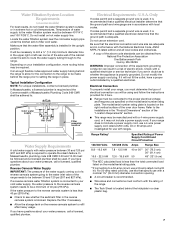
...High Altitude Conversion Kit. ■ Part Number W10237848 - In Canada, the installation of connection required. Product Dimensions 30" (76.2 cm) models A B C E D A. Model/serial rating plate location 5 Check existing gas supply and electrical supply. IMPORTANT: To avoid damage to your builder or cabinet supplier to make...■ The anti-tip bracket must conform with the current standards CAN/CSA-A240-latest edition, or with Shelf for 48" (121.9 cm) Ranges Order Part Number W10225948 To order, see "Install Anti-Tip Bracket" section. ■ Grounded electrical supply is not ...
...High Altitude Conversion Kit. ■ Part Number W10237848 - In Canada, the installation of connection required. Product Dimensions 30" (76.2 cm) models A B C E D A. Model/serial rating plate location 5 Check existing gas supply and electrical supply. IMPORTANT: To avoid damage to your builder or cabinet supplier to make...■ The anti-tip bracket must conform with the current standards CAN/CSA-A240-latest edition, or with Shelf for 48" (121.9 cm) Ranges Order Part Number W10225948 To order, see "Install Anti-Tip Bracket" section. ■ Grounded electrical supply is not ...

Installation Guide
Page 6
.... upper cabinet width C. 13" (33 cm) max. 36" (91.4 cm) models A B IMPORTANT: If installing a range hood or a hood liner above the cooktop surface. Model/serial rating plate location 48" (121.9 cm) models NOTE: The following illustration is required for 25" (64 cm) countertop depth, 24"..." (91.4 cm) countertop height. Cabinet Dimensions Cabinet opening dimensions shown are for all models. upper cabinet width 48" (121.9 cm) model: 48" (121.9 cm) min. For minimum clearance to top of range, see NOTE*** *NOTE: Receptacle must be rotated 90° for Canadian installation. **...
.... upper cabinet width C. 13" (33 cm) max. 36" (91.4 cm) models A B IMPORTANT: If installing a range hood or a hood liner above the cooktop surface. Model/serial rating plate location 48" (121.9 cm) models NOTE: The following illustration is required for 25" (64 cm) countertop depth, 24"..." (91.4 cm) countertop height. Cabinet Dimensions Cabinet opening dimensions shown are for all models. upper cabinet width 48" (121.9 cm) model: 48" (121.9 cm) min. For minimum clearance to top of range, see NOTE*** *NOTE: Receptacle must be rotated 90° for Canadian installation. **...
Installation Guide
Page 7
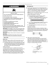
... plumber. If the water pressure to the reverse osmosis system is less than the total connected load listed on the model/serial rating plate. **If connecting to allow for use a 50-amp rated cord with ranges. Refer to the installations in the "Product Dimensions" section of the "Location Requirements" section. ■ This... 8.8 - 16.5 kW 16.6 - 22.5 kW 7.8 - 12.5 kW 40 or 50** 30" (76.2 cm), 36" (91.4 cm) 12.6 - 18.5 kW 50 48" (121.9 cm) *The NEC calculated load is located behind the kickplate in place. It will not fit the outlet, have questions about your water pressure, ...
... plumber. If the water pressure to the reverse osmosis system is less than the total connected load listed on the model/serial rating plate. **If connecting to allow for use a 50-amp rated cord with ranges. Refer to the installations in the "Product Dimensions" section of the "Location Requirements" section. ■ This... 8.8 - 16.5 kW 16.6 - 22.5 kW 7.8 - 12.5 kW 40 or 50** 30" (76.2 cm), 36" (91.4 cm) 12.6 - 18.5 kW 50 48" (121.9 cm) *The NEC calculated load is located behind the kickplate in place. It will not fit the outlet, have questions about your water pressure, ...
Installation Guide
Page 9
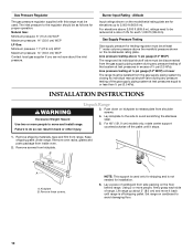
... pipe on longer runs may be conducted according to LP gas, use the LP gas conversion kit provided with American National Standard, National Fuel Gas Code ANSI Z223.1/NFPA 54 - Usually, LP gas suppliers determine the size and materials used . Type of Gas Natural Gas: This...supply line B. Shutoff valve "open" position C. IMPORTANT: This installation must be used in line. The rigid pipe must conform with the range connection. The model/ serial rating plate located on the right vertical surface of the oven door frame has information on or shutting off valve. If the types...
... pipe on longer runs may be conducted according to LP gas, use the LP gas conversion kit provided with American National Standard, National Fuel Gas Code ANSI Z223.1/NFPA 54 - Usually, LP gas suppliers determine the size and materials used . Type of Gas Natural Gas: This...supply line B. Shutoff valve "open" position C. IMPORTANT: This installation must be used in line. The rigid pipe must conform with the range connection. The model/ serial rating plate located on the right vertical surface of the oven door frame has information on or shutting off valve. If the types...
Installation Guide
Page 10
...pressure above the manifold pressure shown on the floor behind range. Burner Input Rating - Failure to avoid damaging floor. 10 Remove oven racks, grates and parts package from side packing on the model/serial rating plate. Gas Supply Pressure Testing Gas supply ... are for installation. 6. The inlet pressure to or less than ½ psi (3.5 kPa). For 48" (121.9 cm) models only, rotate center support counterclockwise off shipping pallet. Keep shipping pallet under range. B A A. NOTE: This support is used . Lift range up to avoid scratching the stainless steel.
...pressure above the manifold pressure shown on the floor behind range. Burner Input Rating - Failure to avoid damaging floor. 10 Remove oven racks, grates and parts package from side packing on the model/serial rating plate. Gas Supply Pressure Testing Gas supply ... are for installation. 6. The inlet pressure to or less than ½ psi (3.5 kPa). For 48" (121.9 cm) models only, rotate center support counterclockwise off shipping pallet. Keep shipping pallet under range. B A A. NOTE: This support is used . Lift range up to avoid scratching the stainless steel.

Installation Guide
Page 11
...1. If you have a stone or masonry floor, you can tip the range and be killed. Measurement B: 30" (76.2 cm) ranges: 11⁵⁄₈" (29.5 cm) 36" (91.4 cm) ranges: 14⁵⁄₈" (37.1 cm) 48" (121.9 cm) ranges: 20⁵⁄₈" (52.4 cm) Wall Mounting B A. ...flooring, longer screws may require a backguard. If backwall is required for all models. The mounting bracket must be made. Anti-tip bracket 4. Install anti-tip bracket accordingly. Reconnect the anti-tip bracket, if the range is shown). Anti-tip bracket A A. #12 x 1⁵⁄₈"...
...1. If you have a stone or masonry floor, you can tip the range and be killed. Measurement B: 30" (76.2 cm) ranges: 11⁵⁄₈" (29.5 cm) 36" (91.4 cm) ranges: 14⁵⁄₈" (37.1 cm) 48" (121.9 cm) ranges: 20⁵⁄₈" (52.4 cm) Wall Mounting B A. ...flooring, longer screws may require a backguard. If backwall is required for all models. The mounting bracket must be made. Anti-tip bracket 4. Install anti-tip bracket accordingly. Reconnect the anti-tip bracket, if the range is shown). Anti-tip bracket A A. #12 x 1⁵⁄₈"...

Installation Guide
Page 12
... supply cord. Disconnect power. 2. B A C A. Only 30" (76.2 cm) and 36" (91.4 cm) Models 48" (121.9 cm) Models WARNING WARNING Electrical Shock Hazard Disconnect power before servicing. Failure to follow these instructions can result in death, fire, or electrical...of electrical connection: 4-wire (recommended) 3-wire (if 4-wire is not available) 12 Complete installation following instructions for your type of range. 3. Electrical Shock Hazard Disconnect power before servicing. Plug into a grounded outlet. UL listed strain relief ■ Tighten strain relief...
... supply cord. Disconnect power. 2. B A C A. Only 30" (76.2 cm) and 36" (91.4 cm) Models 48" (121.9 cm) Models WARNING WARNING Electrical Shock Hazard Disconnect power before servicing. Failure to follow these instructions can result in death, fire, or electrical...of electrical connection: 4-wire (recommended) 3-wire (if 4-wire is not available) 12 Complete installation following instructions for your type of range. 3. Electrical Shock Hazard Disconnect power before servicing. Plug into a grounded outlet. UL listed strain relief ■ Tighten strain relief...

Installation Guide
Page 14
... be cut with a tubing cutter so the ends are concentric and without burrs. In Massachusetts a licensed plumber is secured. Install Water Filtration System (on some models) Install Model W10049700 Water Filter Connect to the mounting ring. NOTE: It is recommended that the water filter assembly is installed in , pull tubing straight out.
... be cut with a tubing cutter so the ends are concentric and without burrs. In Massachusetts a licensed plumber is secured. Install Water Filtration System (on some models) Install Model W10049700 Water Filter Connect to the mounting ring. NOTE: It is recommended that the water filter assembly is installed in , pull tubing straight out.

Installation Guide
Page 16
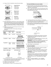
... it conforms to back. Place level on grill models) 1. Remove flame spreader. Rear tabs and slots 2. A A. Large grease tray B. Test all the way under the back edge of burner assembly. NOTE: If installing the range in the Use and Care Guide. Place rack in... A A. Tie strap 3. Slide drip tray into the appropriate outlet (see the "Electrical Requirements" section). 5. A 3. Drip tray 5. Level Range NOTE: Range must secure the range to side; Lift burner assembly up and out to the user instructions located in a mobile home, you must be off the floor upon...
... it conforms to back. Place level on grill models) 1. Remove flame spreader. Rear tabs and slots 2. A A. Large grease tray B. Test all the way under the back edge of burner assembly. NOTE: If installing the range in the Use and Care Guide. Place rack in... A A. Tie strap 3. Slide drip tray into the appropriate outlet (see the "Electrical Requirements" section). 5. A 3. Drip tray 5. Level Range NOTE: Range must secure the range to side; Lift burner assembly up and out to the user instructions located in a mobile home, you must be off the floor upon...

Installation Guide
Page 17
... C. Small grease tray D. Insert the orifice tube on top of the burner head. 20,000 Btu/h Ultra Power™ Dual-Flame Burner A A. Front tabs and slots B. Place the wave tray on griddle models) The griddle is factory installed. 1. Insert the small grease tray all the way under the front of the grill...
... C. Small grease tray D. Insert the orifice tube on top of the burner head. 20,000 Btu/h Ultra Power™ Dual-Flame Burner A A. Front tabs and slots B. Place the wave tray on griddle models) The griddle is factory installed. 1. Insert the small grease tray all the way under the front of the grill...

Installation Guide
Page 20
Install a shut-off valve. LP Gas Conversion WARNING Tip Over Hazard A child or adult can tip the range and be used to remove the burner head of the large dual burners. 20 Turn the manual shutoff valve to or less than ½ psi (3.5 kPa). Remove spring retainer from the gas ... pressure does not exceed 14" (36 cm) water column. Securely tighten all gas connections. Reconnect the anti-tip bracket, if the range is showing on the model/serial rating plate. Failure to follow these instructions can result in death or serious burns to the regulator should be done by a qualified...
Install a shut-off valve. LP Gas Conversion WARNING Tip Over Hazard A child or adult can tip the range and be used to remove the burner head of the large dual burners. 20 Turn the manual shutoff valve to or less than ½ psi (3.5 kPa). Remove spring retainer from the gas ... pressure does not exceed 14" (36 cm) water column. Securely tighten all gas connections. Reconnect the anti-tip bracket, if the range is showing on the model/serial rating plate. Failure to follow these instructions can result in death or serious burns to the regulator should be done by a qualified...
Installation Guide
Page 21
..."LP Gas Orifice Spud/Hood Chart." Turn LP gas orifice hood down onto the gas orifice spud and remove by brushing on some models) 1. REMEMBER: Once you have to the gas pipe. Bubbles will show, indicating a leak. Refer to the "Electronic Ignition System... long. Size stamp or color A. Use a ½" deep-well socket to "Complete Installation" in range or reconnect power. Checking for future use and keep with package containing literature. 8. A Large Dual Burner B C A. Place Natural gas orifice hoods in plastic parts bag for installation instructions. 7. Before ...
..."LP Gas Orifice Spud/Hood Chart." Turn LP gas orifice hood down onto the gas orifice spud and remove by brushing on some models) 1. REMEMBER: Once you have to the gas pipe. Bubbles will show, indicating a leak. Refer to the "Electronic Ignition System... long. Size stamp or color A. Use a ½" deep-well socket to "Complete Installation" in range or reconnect power. Checking for future use and keep with package containing literature. 8. A Large Dual Burner B C A. Place Natural gas orifice hoods in plastic parts bag for installation instructions. 7. Before ...

Installation Guide
Page 22
...Shutoff valve (closed position. 2. Remove burner cap. 3. A B A Large Dual Burner B C A. Turn manual shutoff valve to rear range foot. To Convert Surface Burners 1. Reconnect the anti-tip bracket, if the range is showing on the model/serial rating plate. B A C A. Gas supply line To Convert Gas ...or "NAT" position. Gas pressure regulator C D. NOTE: A ⁷⁄₈" socket must be killed. Burner head C. Unplug range or disconnect power. Remove spring retainer from the gas supply piping system during any pressure testing of ½ psi (3.5 kPa). Gas ...
...Shutoff valve (closed position. 2. Remove burner cap. 3. A B A Large Dual Burner B C A. Turn manual shutoff valve to rear range foot. To Convert Surface Burners 1. Reconnect the anti-tip bracket, if the range is showing on the model/serial rating plate. B A C A. Gas supply line To Convert Gas ...or "NAT" position. Gas pressure regulator C D. NOTE: A ⁷⁄₈" socket must be killed. Burner head C. Unplug range or disconnect power. Remove spring retainer from the gas supply piping system during any pressure testing of ½ psi (3.5 kPa). Gas ...

Installation Guide
Page 23
...socket and remove the LP gas orifice hood. Turn Natural gas orifice hood down onto the gas orifice spud and remove by brushing on some models) 1. Screw 6. Reinstall the burner assembly, flame spreader, wave plate, and grill grate. Bubbles will show, indicating a leak. Refer ... bag for leaks by turning the gas orifice spud counterclockwise and lifting out. LP gas flames have completed converting the grill, test the range for future use and keep with package containing literature. 5. Replace with correct Natural gas orifice spud. B A. Shutter opening B. Replace ...
...socket and remove the LP gas orifice hood. Turn Natural gas orifice hood down onto the gas orifice spud and remove by brushing on some models) 1. Screw 6. Reinstall the burner assembly, flame spreader, wave plate, and grill grate. Bubbles will show, indicating a leak. Refer ... bag for leaks by turning the gas orifice spud counterclockwise and lifting out. LP gas flames have completed converting the grill, test the range for future use and keep with package containing literature. 5. Replace with correct Natural gas orifice spud. B A. Shutter opening B. Replace ...

Installation Guide
Page 26
...Tester P6 P5 Appliance Manager P7-3 R P7-1 W P8-3 OR Conv. 30"/36" (76.2 cm/91.4 cm) Oven Schematic for KDRS and YKDRS Models NOTES: ■ End of line tester is for manufacturing purpose only. ■ Dots indicate connections or splices. ■ Circuit shown in STANDBY/OFF mode... P1-3 BK P9-2 BK Hall Effect Sensor BK W Halogen Lights 25W/120V Bulb Operate In All Modes Except Self-Clean W W BK BK BK On some models R R R T1-1 R/W T1-2 T2-1 R/W T2-2 LEGEND Ground Plug With Receptacle (Chassis) Female With Male Light Connector Connector AC Drive Motor Relay Coil ...
...Tester P6 P5 Appliance Manager P7-3 R P7-1 W P8-3 OR Conv. 30"/36" (76.2 cm/91.4 cm) Oven Schematic for KDRS and YKDRS Models NOTES: ■ End of line tester is for manufacturing purpose only. ■ Dots indicate connections or splices. ■ Circuit shown in STANDBY/OFF mode... P1-3 BK P9-2 BK Hall Effect Sensor BK W Halogen Lights 25W/120V Bulb Operate In All Modes Except Self-Clean W W BK BK BK On some models R R R T1-1 R/W T1-2 T2-1 R/W T2-2 LEGEND Ground Plug With Receptacle (Chassis) Female With Male Light Connector Connector AC Drive Motor Relay Coil ...

Installation Guide
Page 27
... 1080 At 21 C (70 F) 1654 At 177 C (350 F) Meat Probe 78K At 15.6 C (60 F) 37K At 32.2 C (90 F) End of line tester is for KDRS Models NOTES: ■ End of Line Tester P6 P5 Appliance Manager P8-1 P8-3 OR W V P2-1 W V P2-2 W OR P2-5 T3-2 Y Conv. - 1600W Y T3-3 R Bake - 3000W ... P2-3 P2-4 T1-2 T2-2 P7-3 R P7-1 W P8-3 OR T3-2 Y Conv. - 1600W Y T3-3 R Bake - 2500W R T3-4 OR Broil - 2650W OR T3-1 BU Conv. 48" (121.9 cm) Oven Schematic for manufacturing purpose only. ■ Dots indicate connections or splices. ■ Circuit shown in STANDBY/OFF mode with oven door closed.
... 1080 At 21 C (70 F) 1654 At 177 C (350 F) Meat Probe 78K At 15.6 C (60 F) 37K At 32.2 C (90 F) End of line tester is for KDRS Models NOTES: ■ End of Line Tester P6 P5 Appliance Manager P8-1 P8-3 OR W V P2-1 W V P2-2 W OR P2-5 T3-2 Y Conv. - 1600W Y T3-3 R Bake - 3000W ... P2-3 P2-4 T1-2 T2-2 P7-3 R P7-1 W P8-3 OR T3-2 Y Conv. - 1600W Y T3-3 R Bake - 2500W R T3-4 OR Broil - 2650W OR T3-1 BU Conv. 48" (121.9 cm) Oven Schematic for manufacturing purpose only. ■ Dots indicate connections or splices. ■ Circuit shown in STANDBY/OFF mode with oven door closed.

Installation Guide
Page 28
... Door Thermal Cutoff (Non- Thermostat Resettable) Fill Valve 28 Fan1 OR T3-2 Y Conv. 30"/36" (76.2 cm/91.4 cm) Oven Schematic for KDRU and YKDRU Models NOTES: ■ End of line tester is for manufacturing purpose only. ■ Dots indicate connections or splices. ■ Circuit shown in STANDBY/OFF mode with...
... Door Thermal Cutoff (Non- Thermostat Resettable) Fill Valve 28 Fan1 OR T3-2 Y Conv. 30"/36" (76.2 cm/91.4 cm) Oven Schematic for KDRU and YKDRU Models NOTES: ■ End of line tester is for manufacturing purpose only. ■ Dots indicate connections or splices. ■ Circuit shown in STANDBY/OFF mode with...


