

User Manual
Page 3
... discs and tapes 5 System connection (XD-7...series 6 Connection of the System Accessories 6 Connection of Options (Optional Parts 8 System connection (XD-5...series 10 Connection of the System Accessories 10 Connection of Options (Optional Parts 12 Controls and indicators 14 Main Unit 14 Display 16 Remote control Unit 17 Operation of remote control unit 18 CHANNEL SPACE setting 18 Basic section Let's put out some sound 20 Basic use method 20 Playback of CD 22 Playback of tape 24 Searching for the desired music program...
... discs and tapes 5 System connection (XD-7...series 6 Connection of the System Accessories 6 Connection of Options (Optional Parts 8 System connection (XD-5...series 10 Connection of the System Accessories 10 Connection of Options (Optional Parts 12 Controls and indicators 14 Main Unit 14 Display 16 Remote control Unit 17 Operation of remote control unit 18 CHANNEL SPACE setting 18 Basic section Let's put out some sound 20 Basic use method 20 Playback of CD 22 Playback of tape 24 Searching for the desired music program...

User Manual
Page 4
... immediately. Built in the speaker package) Easy to reproduce heavy bass more powerfully than conventional system speakers. 3-Disc carousel CD player ™ Three discs can be selected from preset patterns, but the audio does not change. Versatile tone and sound field adjustment p Equalizer patterns can file a claim against the carrier for enjoyment at a glance. MODE /DEMO ÷ Press the key during use should you directly, notify the shipping...
... immediately. Built in the speaker package) Easy to reproduce heavy bass more powerfully than conventional system speakers. 3-Disc carousel CD player ™ Three discs can be selected from preset patterns, but the audio does not change. Versatile tone and sound field adjustment p Equalizer patterns can file a claim against the carrier for enjoyment at a glance. MODE /DEMO ÷ Press the key during use should you directly, notify the shipping...
User Manual
Page 5
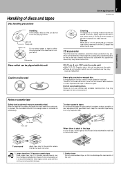
... to remove the slack. Preparation section Handling of discs and tapes Disc handling precautions 5 Before applying power XD-SERIES (En) Handling Hold compact discs so that you do not use discs which are marketed for a long period of compact discs. During playback, the disc rotates at high speed in its case. Keep the cassette tapes away from the CD player and store it in the player. Sticky paste Discs...
... to remove the slack. Preparation section Handling of discs and tapes Disc handling precautions 5 Before applying power XD-SERIES (En) Handling Hold compact discs so that you do not use discs which are marketed for a long period of compact discs. During playback, the disc rotates at high speed in its case. Keep the cassette tapes away from the CD player and store it in the player. Sticky paste Discs...

User Manual
Page 6
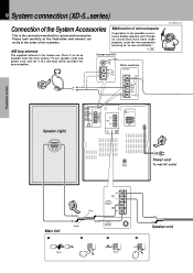
... XD-SERIES (En) Speaker (right) −+ L ANTENNA R AUX OUTPUT L R AUX INPUT AUX INPUT LEVEL FM 75Ω GND FM 300Ω AM MIN. If operation is for system and accessories. properly, reset the microcomputer referring to a direction which provides the best reception. possible from the main system, TV set, speaker cords and power cord, and set it as far as Europe and U.K. MAX. + L - - R + SUB WOOFER SPEAKERS (12-16Ω) + L - - Preparation section 6 System connection (XD-7...series) Connection of the System Accessories...
... XD-SERIES (En) Speaker (right) −+ L ANTENNA R AUX OUTPUT L R AUX INPUT AUX INPUT LEVEL FM 75Ω GND FM 300Ω AM MIN. If operation is for system and accessories. properly, reset the microcomputer referring to a direction which provides the best reception. possible from the main system, TV set, speaker cords and power cord, and set it as far as Europe and U.K. MAX. + L - - R + SUB WOOFER SPEAKERS (12-16Ω) + L - - Preparation section 6 System connection (XD-7...series) Connection of the System Accessories...

User Manual
Page 7
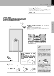
... cm away from the TV set. 7 System connection (XD-7...series) XD-SERIES (En) Caution regarding placement To maintain proper ventilation, be produced or 4 noise may cause color blotching onthe TV. If their connections are imper- For stable signal reception we recommend using an outdoor antenna. Speaker and TV installation If there is connected, also read the instruction manual of the component. 2. Never short-circuit the + and...
... cm away from the TV set. 7 System connection (XD-7...series) XD-SERIES (En) Caution regarding placement To maintain proper ventilation, be produced or 4 noise may cause color blotching onthe TV. If their connections are imper- For stable signal reception we recommend using an outdoor antenna. Speaker and TV installation If there is connected, also read the instruction manual of the component. 2. Never short-circuit the + and...

User Manual
Page 8
... DIGITAL OUT jack (OPTICAL) If necessary, remove the cap and plug the optical-fiber cable (optional). Preparation section 8 Connection of the required connections have been made. Audio output MD recorder Audio input 1 2 Surround (rear) speakers R L 3 −+ −+ L R AUX OUTPUT L R AUX INPUT AUX INPUT LEVEL L ANTENNA R AUX OUTPUT L R AUX INPUT AUX INPUT LEVEL FM 75Ω GND FM 300Ω AM MIN. When the switch is set to OFF, no surround (rear) speakers are connected to obtain a better sound quality. ÷ When the switch is set to the SURROUND...
... DIGITAL OUT jack (OPTICAL) If necessary, remove the cap and plug the optical-fiber cable (optional). Preparation section 8 Connection of the required connections have been made. Audio output MD recorder Audio input 1 2 Surround (rear) speakers R L 3 −+ −+ L R AUX OUTPUT L R AUX INPUT AUX INPUT LEVEL L ANTENNA R AUX OUTPUT L R AUX INPUT AUX INPUT LEVEL FM 75Ω GND FM 300Ω AM MIN. When the switch is set to OFF, no surround (rear) speakers are connected to obtain a better sound quality. ÷ When the switch is set to the SURROUND...
User Manual
Page 10
... order of the numbers. properly, reset the microcomputer referring to a direction which provides the best reception. AM loop antenna P The supplied antenna is the connection method for indoor use. Place it to "In case of difficulty". MAX. + L - 10 System connection (XD-5...series) Connection of the System Accessories Malfunction of microcomputer This is for system and accessories. possible from the main system, TV set, speaker cords and power cord, and set it as far...
... order of the numbers. properly, reset the microcomputer referring to a direction which provides the best reception. AM loop antenna P The supplied antenna is the connection method for indoor use. Place it to "In case of difficulty". MAX. + L - 10 System connection (XD-5...series) Connection of the System Accessories Malfunction of microcomputer This is for system and accessories. possible from the main system, TV set, speaker cords and power cord, and set it as far...
User Manual
Page 11
... ) BASS REFLEX SPEAKER SYSTEM BASS REFLEX SPEAKER SYSTEM −+ The external view is connected, also read the instruction manual of musical instruments, etc. Be sure to connect them from the largest outer dimensions including projections) equal to insert all connection cords securely. plugged with unclear positioning of the component. 2. If connection cords are plugged or un- Speaker cushion 2 3 Notes 1. rear panel: 10 cm FM indoor antenna The accessory antenna is for temporary indoor use...
... ) BASS REFLEX SPEAKER SYSTEM BASS REFLEX SPEAKER SYSTEM −+ The external view is connected, also read the instruction manual of musical instruments, etc. Be sure to connect them from the largest outer dimensions including projections) equal to insert all connection cords securely. plugged with unclear positioning of the component. 2. If connection cords are plugged or un- Speaker cushion 2 3 Notes 1. rear panel: 10 cm FM indoor antenna The accessory antenna is for temporary indoor use...

User Manual
Page 12
... operate this switch while the power is played back powerfully. Preparation section Audio output MD recorder Audio input 1 2 Surround (rear) speakers R L 3 −+ −+ Basic section L R AUX OUTPUT L R AUX INPUT AUX INPUT LEVEL L ANTENNA R AUX OUTPUT L R AUX INPUT AUX INPUT LEVEL FM 75Ω GND FM 300Ω AM MIN. FRONT SPEAKERS (6-16Ω) - This can be enjoyed. MAX. % ON SURROUND fi OFF -+ L R SURROUND SPEAKERS (8-16Ω) Optical-fiber cable DIGITAL OUT OPTICAL (Provided with any type of playback. Do not plug the power cord...
... operate this switch while the power is played back powerfully. Preparation section Audio output MD recorder Audio input 1 2 Surround (rear) speakers R L 3 −+ −+ Basic section L R AUX OUTPUT L R AUX INPUT AUX INPUT LEVEL L ANTENNA R AUX OUTPUT L R AUX INPUT AUX INPUT LEVEL FM 75Ω GND FM 300Ω AM MIN. FRONT SPEAKERS (6-16Ω) - This can be enjoyed. MAX. % ON SURROUND fi OFF -+ L R SURROUND SPEAKERS (8-16Ω) Optical-fiber cable DIGITAL OUT OPTICAL (Provided with any type of playback. Do not plug the power cord...

User Manual
Page 14
...MIC VOL. MIN MAX SOUND SET 0 PUSH OPEN DOWN MULTI CONTROL SRS 3D CD PGM DUBBING ENTER TUNING BAND AUTO PHONES 0 PUSH OPEN PLAY REC /PLAY DISC 1 REV.MODE DOLBY NR 1 2 7 DISC 2 DISC SKIP DISC 3 REC/ARM 3 ¡ A/B 0 4¢ 76 & * ( Basic section Application section Knowledge sections and Canada) 7 890 ! @ # $%^ 1 2 3 4 5 6 ) ¡ ™ ¶ • ª MINI HiFi COMPONENT SYSTEM SRS ( ) UP VOLUME CONTROL ON/STANDBY EX. BASS DISPLAY TIMER MODE /DEMO 1- 14 Controls and indicators Main Unit XD-SERIES (En) Preparation section POWER (For...
...MIC VOL. MIN MAX SOUND SET 0 PUSH OPEN DOWN MULTI CONTROL SRS 3D CD PGM DUBBING ENTER TUNING BAND AUTO PHONES 0 PUSH OPEN PLAY REC /PLAY DISC 1 REV.MODE DOLBY NR 1 2 7 DISC 2 DISC SKIP DISC 3 REC/ARM 3 ¡ A/B 0 4¢ 76 & * ( Basic section Application section Knowledge sections and Canada) 7 890 ! @ # $%^ 1 2 3 4 5 6 ) ¡ ™ ¶ • ª MINI HiFi COMPONENT SYSTEM SRS ( ) UP VOLUME CONTROL ON/STANDBY EX. BASS DISPLAY TIMER MODE /DEMO 1- 14 Controls and indicators Main Unit XD-SERIES (En) Preparation section POWER (For...

User Manual
Page 15
... the equalizer mode setting, etc. 15 Controls and indicators XD-SERIES (En) ! Pressing the key during recording of various modes or establishing a selection. 0 SOUND key/Indicator pQ Used for insertion of a CD to load or eject a tape. ¡ DOLBY NR key ∞ Dolby noise reduction ON/OFF switching is STANDBY: Switches the demonstration on and off . 8 TIMER key RI Used for time adjustment, timer setting, etc. 9 SET key ¡ Used for volume adjustment. *Tuner operation keys •...
... the equalizer mode setting, etc. 15 Controls and indicators XD-SERIES (En) ! Pressing the key during recording of various modes or establishing a selection. 0 SOUND key/Indicator pQ Used for insertion of a CD to load or eject a tape. ¡ DOLBY NR key ∞ Dolby noise reduction ON/OFF switching is STANDBY: Switches the demonstration on and off . 8 TIMER key RI Used for time adjustment, timer setting, etc. 9 SET key ¡ Used for volume adjustment. *Tuner operation keys •...

User Manual
Page 16
STEREO 0 ECHO 1 2 3 NR O.T.T. Guideline Blinks during volume control. ! It also shows the approximate sound level during the setting of an item using the jog dial. ( Knowledge sections 16 Display (The displays given in this manual are approximations only. The indicated information includes the tape reverse mode and tape transport direction. 7CD player indicators This section displays the CD playback and pause mode information as well as the disc number being played. 8Track...
STEREO 0 ECHO 1 2 3 NR O.T.T. Guideline Blinks during volume control. ! It also shows the approximate sound level during the setting of an item using the jog dial. ( Knowledge sections 16 Display (The displays given in this manual are approximations only. The indicated information includes the tape reverse mode and tape transport direction. 7CD player indicators This section displays the CD playback and pause mode information as well as the disc number being played. 8Track...
User Manual
Page 17
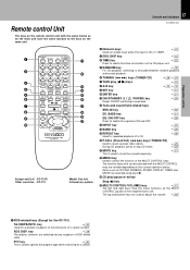
... (7) key )MULTI CONTROL/VOLUME keys ¡ The left . PTY POWER 1 2 3 SRS 3D 4 5 6 EX.BASS 7 8 9 EQ ON/OFF DISC SKIP 0 +10 INPUT TIME RANDOM REPEAT BAND TUNING TAPE CD A/B P.CALL MUTE MENU SET ENTER VOLUME MULTI CONTROL REMOTE CONTROL UNIT RC-701R ! @ Europe and U.K. : RC-701R Other countries : RC-701 Model: See left and right keys have the same function as CD PGM, DUBBING, SOUND, DISPLAY, TIMER and MODE are selected using keys ). ( CD play (2 3) keys...
... (7) key )MULTI CONTROL/VOLUME keys ¡ The left . PTY POWER 1 2 3 SRS 3D 4 5 6 EX.BASS 7 8 9 EQ ON/OFF DISC SKIP 0 +10 INPUT TIME RANDOM REPEAT BAND TUNING TAPE CD A/B P.CALL MUTE MENU SET ENTER VOLUME MULTI CONTROL REMOTE CONTROL UNIT RC-701R ! @ Europe and U.K. : RC-701R Other countries : RC-701 Model: See left and right keys have the same function as CD PGM, DUBBING, SOUND, DISPLAY, TIMER and MODE are selected using keys ). ( CD play (2 3) keys...

User Manual
Page 20
... out some sound Basic use method XD-SERIES (En) Preparation section Basic section Bass and treble compensation TIMER, MODE/DEMO 1 3 EX.BASS 2 Muting the sound temporarily SET ENTER Listening through headphones Insert the headphone plug into deck B. 3. Volume adjustment DOWN 3 ÷ Quick turning produces a larger change amount. (AI VOLUME control function) ÷ The display shows a reference value. Selecting the desired output TUNER (Radio) CD TAPE AUX (External input) • ™ ¢ 8@ ÷ When you select the AUX input, be...
... out some sound Basic use method XD-SERIES (En) Preparation section Basic section Bass and treble compensation TIMER, MODE/DEMO 1 3 EX.BASS 2 Muting the sound temporarily SET ENTER Listening through headphones Insert the headphone plug into deck B. 3. Volume adjustment DOWN 3 ÷ Quick turning produces a larger change amount. (AI VOLUME control function) ÷ The display shows a reference value. Selecting the desired output TUNER (Radio) CD TAPE AUX (External input) • ™ ¢ 8@ ÷ When you select the AUX input, be...

User Manual
Page 21
... executed for the XD-5...series) XD-SERIES (En) Adjust the sub woofer level according to as the STANDBY mode, and the unit in the STANDBY mode can be turned ON from the remote control unit. OFF .... MULTI CONTROL AUTOTPOW ER | Scrolled display (AUTO POWER SAVE) ON ..... RETURN ÷ This function is not available when the AUX input is not ENTER used . Knowledge sections BASS ÷ Each press switches EX.BASS on and off...
... executed for the XD-5...series) XD-SERIES (En) Adjust the sub woofer level according to as the STANDBY mode, and the unit in the STANDBY mode can be turned ON from the remote control unit. OFF .... MULTI CONTROL AUTOTPOW ER | Scrolled display (AUTO POWER SAVE) ON ..... RETURN ÷ This function is not available when the AUX input is not ENTER used . Knowledge sections BASS ÷ Each press switches EX.BASS on and off...

User Manual
Page 49
... Knowledge sections Select the sound field mode according to the music genre. AUX INPUT LEVEL + + MIN. Adjusts the balance of equalizer and sound field playback. ENTER The left and right volume. MULTI CONTROL SET 3 Adjust. 1 Adjust. The level is decreased. Indicates the center L--y--R Indicates the balance setting Input level adjustment : Rear panel L ANTENNA FM R AUX 75Ω OUTPUT L R AUX INPUT AUX INPUT LEVEL AM GND FM 300Ω MIN. Effective Sound Adjustment 49 XD-SERIES (En) This unit permits...
... Knowledge sections Select the sound field mode according to the music genre. AUX INPUT LEVEL + + MIN. Adjusts the balance of equalizer and sound field playback. ENTER The left and right volume. MULTI CONTROL SET 3 Adjust. 1 Adjust. The level is decreased. Indicates the center L--y--R Indicates the balance setting Input level adjustment : Rear panel L ANTENNA FM R AUX 75Ω OUTPUT L R AUX INPUT AUX INPUT LEVEL AM GND FM 300Ω MIN. Effective Sound Adjustment 49 XD-SERIES (En) This unit permits...

User Manual
Page 56
... to radio ÷ To listen to CD ÷ To listen to tape The station should be activated or not as required. ÷ Timer reservation is possible for record- Program 1 PROG.2 ...... Program 2 AUTO POWER SAVE PROG 1 ÷ The selected program No. A ÷ Playing the auxiliary input source Make timer setting of timer playback. 2 Adjust the listening volume. and press the SET key. PROG. 56 Adjust the clock before setting the timer. ÷ If you made a mistake during timer setting...
... to radio ÷ To listen to CD ÷ To listen to tape The station should be activated or not as required. ÷ Timer reservation is possible for record- Program 1 PROG.2 ...... Program 2 AUTO POWER SAVE PROG 1 ÷ The selected program No. A ÷ Playing the auxiliary input source Make timer setting of timer playback. 2 Adjust the listening volume. and press the SET key. PROG. 56 Adjust the clock before setting the timer. ÷ If you made a mistake during timer setting...

User Manual
Page 57
... CONTROL ENTER TUNER (Radio) CD TAPE AUX (External input) RETURN TUNER Enter it . ÷ If you selected TUNER, press the SET key. 3 Select the broadcast station (only when TUNER is returned. Application section 8 Press the TIMER key. MULTI CONTROL Select "TIMER REC". SLEEP | Scrolled display (PROG. ON/OFF) TIME SET O.T.T. Program 2 AUTO POWER SAVE 6 Enter the OFF time. 1 MULTI CONTROL 57 Adjust the clock before setting the timer. creasing volume SET RETURN Enter it . 2 Select the input source. ON/OFF PROG.1 ...... SET...
... CONTROL ENTER TUNER (Radio) CD TAPE AUX (External input) RETURN TUNER Enter it . ÷ If you selected TUNER, press the SET key. 3 Select the broadcast station (only when TUNER is returned. Application section 8 Press the TIMER key. MULTI CONTROL Select "TIMER REC". SLEEP | Scrolled display (PROG. ON/OFF) TIME SET O.T.T. Program 2 AUTO POWER SAVE 6 Enter the OFF time. 1 MULTI CONTROL 57 Adjust the clock before setting the timer. creasing volume SET RETURN Enter it . 2 Select the input source. ON/OFF PROG.1 ...... SET...

User Manual
Page 59
... for these agents may deform the plastic component. Preparation section Basic section Application section Reference Sound Retrieval System manufactured under licence from power outlet Amplifier POWER status (ON or OFF) Input selection Volume control value Equalizer's manual memory created by the user SRS 3D level Tuner unit Receiving band Frequency Preset stations Program timer setting contents Cassette deck unit Transport direction DOLBY NR Reverse mode Knowledge sections When your unit needs...
... for these agents may deform the plastic component. Preparation section Basic section Application section Reference Sound Retrieval System manufactured under licence from power outlet Amplifier POWER status (ON or OFF) Input selection Volume control value Equalizer's manual memory created by the user SRS 3D level Tuner unit Receiving band Frequency Preset stations Program timer setting contents Cassette deck unit Transport direction DOLBY NR Reverse mode Knowledge sections When your unit needs...

User Manual
Page 60
... power cord was not set in the TUNER mode. ÷ Sound is not output when the radio wave is set to condition when it left or ÷ The speaker cords are exhausted. ÷ The remote control is too far away from the left the factory. Operation to reset The microcomputer may fall into the jack. ÷ Connect properly referring to "System connection". ÷ Switch MUTE OFF. ÷ Unplug the headphone plug. ) AUX (external input) sound...
... power cord was not set in the TUNER mode. ÷ Sound is not output when the radio wave is set to condition when it left or ÷ The speaker cords are exhausted. ÷ The remote control is too far away from the left the factory. Operation to reset The microcomputer may fall into the jack. ÷ Connect properly referring to "System connection". ÷ Switch MUTE OFF. ÷ Unplug the headphone plug. ) AUX (external input) sound...


