

User Manual
Page 3
... DSP • Digital Noise Blanker • PC interface via a Universal Serial Bus port (B-type) • Drive output and RX only antenna connector • Direct band keys • Built-in the vehicle. These limits are expressly approved in a residential installation. The maximum transmission output power is technically sophisticated and some features may cause harmful interference unless the modifications are designed to the specifications {page 81...
... DSP • Digital Noise Blanker • PC interface via a Universal Serial Bus port (B-type) • Drive output and RX only antenna connector • Direct band keys • Built-in the vehicle. These limits are expressly approved in a residential installation. The maximum transmission output power is technically sophisticated and some features may cause harmful interference unless the modifications are designed to the specifications {page 81...
User Manual
Page 6
...1 INSTALLATION ANTENNA CONNECTION 1 GROUND CONNECTION 1 LIGHTNING PROTECTION 1 DC POWER SUPPLY CONNECTION 1 UTILIZING THE BAIL 2 REPLACING FUSES 2 ACCESSORY CONNECTIONS 2 FRONT PANEL 2 Headphones (PHONES 2 Microphone (MIC 2 REAR PANEL 2 External Speaker (EXT.SP 2 Keys for CW (PADDLE and KEY 2 CHAPTER 2 GETTING ACQUAINTED FRONT PANEL 4 LCD DISPLAY 7 REAR PANEL 9 MICROPHONE 9 CHAPTER 3 OPERATING BASICS SWITCHING POWER ON/ OFF 10 ADJUSTING THE VOLUME 10 AF (AUDIO FREQUENCY) GAIN 10 RF (RADIO FREQUENCY) GAIN 10 SELECTING VFO A OR VFO B 10 SELECTING A BAND 11 SELECTING A MODE...
...1 INSTALLATION ANTENNA CONNECTION 1 GROUND CONNECTION 1 LIGHTNING PROTECTION 1 DC POWER SUPPLY CONNECTION 1 UTILIZING THE BAIL 2 REPLACING FUSES 2 ACCESSORY CONNECTIONS 2 FRONT PANEL 2 Headphones (PHONES 2 Microphone (MIC 2 REAR PANEL 2 External Speaker (EXT.SP 2 Keys for CW (PADDLE and KEY 2 CHAPTER 2 GETTING ACQUAINTED FRONT PANEL 4 LCD DISPLAY 7 REAR PANEL 9 MICROPHONE 9 CHAPTER 3 OPERATING BASICS SWITCHING POWER ON/ OFF 10 ADJUSTING THE VOLUME 10 AF (AUDIO FREQUENCY) GAIN 10 RF (RADIO FREQUENCY) GAIN 10 SELECTING VFO A OR VFO B 10 SELECTING A BAND 11 SELECTING A MODE...

User Manual
Page 7
... 54 MICROPHONE KEYS 54 DSP RX EQUALIZER 55 Equalizing Receiving Audio 55 RX MONITOR 55 TIME-OUT TIMER 55 TRANSVERTER 55 FREQUENCY DISPLAY 55 TRANSMISSION OUTPUT POWER 56 TX MONITOR 56 TX POWER 56 TX TUNE 56 QUICK DATA TRANSFER 56 SETTING UP 56 Equipment Needed 56 Connections 56 USING QUICK TRANSFER 57 Transferring Data 57 Receiving Data 57 COMPUTER CONTROL 57 SETTING UP 57 Equipment Needed 57 Connections 57 COMMUNICATION PARAMETERS 57 EXTERNAL AUDIO SETTINGS 58 Selecting a Data...
... 54 MICROPHONE KEYS 54 DSP RX EQUALIZER 55 Equalizing Receiving Audio 55 RX MONITOR 55 TIME-OUT TIMER 55 TRANSVERTER 55 FREQUENCY DISPLAY 55 TRANSMISSION OUTPUT POWER 56 TX MONITOR 56 TX POWER 56 TX TUNE 56 QUICK DATA TRANSFER 56 SETTING UP 56 Equipment Needed 56 Connections 56 USING QUICK TRANSFER 57 Transferring Data 57 Receiving Data 57 COMPUTER CONTROL 57 SETTING UP 57 Equipment Needed 57 Connections 57 COMMUNICATION PARAMETERS 57 EXTERNAL AUDIO SETTINGS 58 Selecting a Data...
User Manual
Page 8
... REPEATER 70 CHAPTER 14 INSTALLING OPTIONS REMOVING THE BOTTOM CASE 71 VGS-1 VOICE GUIDE & STORAGE UNIT 71 SO-3 TCXO 72 REFERENCE FREQUENCY CALIBRATION ....... 72 MB-430 MOBILE BRACKET 73 PRECAUTIONS 73 CHAPTER 15 TROUBLESHOOTING GENERAL INFORMATION 74 SERVICE 74 SERVICE NOTE 74 CLEANING 74 TROUBLESHOOTING 75 MICROPROCESSOR RESET 78 INITIAL SETTINGS 78 VFO RESET 78 FULL RESET 78 OPERATION NOTICES 79 DC POWER SUPPLY 79 INTERNAL COOLING...
... REPEATER 70 CHAPTER 14 INSTALLING OPTIONS REMOVING THE BOTTOM CASE 71 VGS-1 VOICE GUIDE & STORAGE UNIT 71 SO-3 TCXO 72 REFERENCE FREQUENCY CALIBRATION ....... 72 MB-430 MOBILE BRACKET 73 PRECAUTIONS 73 CHAPTER 15 TROUBLESHOOTING GENERAL INFORMATION 74 SERVICE 74 SERVICE NOTE 74 CLEANING 74 TROUBLESHOOTING 75 MICROPROCESSOR RESET 78 INITIAL SETTINGS 78 VFO RESET 78 FULL RESET 78 OPERATION NOTICES 79 DC POWER SUPPLY 79 INTERNAL COOLING...
User Manual
Page 9
... the ground, then connect this entry panel to radio frequency interference with smaller gauge wires. When a lightning storm occurs, disconnecting the feed lines from the DRV terminal. Use heavy gauge wire or a copper strap, cut as short as stereo receivers and televisions. The installation of these conditions can operate. For example, terminate your transceiver. Do not substitute a cable with consumer products...
... the ground, then connect this entry panel to radio frequency interference with smaller gauge wires. When a lightning storm occurs, disconnecting the feed lines from the DRV terminal. Use heavy gauge wire or a copper strap, cut as short as stereo receivers and televisions. The installation of these conditions can operate. For example, terminate your transceiver. Do not substitute a cable with consumer products...

User Manual
Page 10
... jack accepts a 6.3 mm (1/4") diameter, 2-conductor (mono) or 3-conductor (stereo) plug. Pull the bail forward to blow, disconnect the power plug and contact a Kenwood service center or your hearing. ■ Keys for external antenna tuner) 25 A Fuse (4 A) Fuse (25 A) Fuse (25 A) 2 ACCESSORY CONNECTIONS FRONT PANEL ■ Headphones (PHONES) Connect monaural or stereo headphones with a bail so that you will mute. REPLACING FUSES The following fuses are used in the TS-590S transceiver. The high audio output of...
... jack accepts a 6.3 mm (1/4") diameter, 2-conductor (mono) or 3-conductor (stereo) plug. Pull the bail forward to blow, disconnect the power plug and contact a Kenwood service center or your hearing. ■ Keys for external antenna tuner) 25 A Fuse (4 A) Fuse (25 A) Fuse (25 A) 2 ACCESSORY CONNECTIONS FRONT PANEL ■ Headphones (PHONES) Connect monaural or stereo headphones with a bail so that you will mute. REPLACING FUSES The following fuses are used in the TS-590S transceiver. The high audio output of...
User Manual
Page 17
... instruction manual supplied with a 3.5 mm (1/8"), 2-conductor (mono) plug for connecting a computer via one of these jacks. MICROPHONE PTT (Push-to-Talk) switch The transceiver is held down . REMOTE connector Mates with the transceiver. Refer to continuously change the operational function of its USB ports {pages 57, 67}. Releasing the switch returns the transceiver to Reception mode. / Mic [UP]/ [DWN] Use these keys to "Keys for CW (PADDLE and KEY)" {page 2} before using 2 antennas...
... instruction manual supplied with a 3.5 mm (1/8"), 2-conductor (mono) plug for connecting a computer via one of these jacks. MICROPHONE PTT (Push-to-Talk) switch The transceiver is held down . REMOTE connector Mates with the transceiver. Refer to continuously change the operational function of its USB ports {pages 57, 67}. Releasing the switch returns the transceiver to Reception mode. / Mic [UP]/ [DWN] Use these keys to "Keys for CW (PADDLE and KEY)" {page 2} before using 2 antennas...

User Manual
Page 30
... return to use Auto Zero-beat. This transceiver has a built-in poor conditions. The mode indicator changes to "FM". 2 Press and hold Mic [PTT]. • The TX-RX LED lights red. • Refer to "VOX" {page 30} for information on automatic TX/ RX switching. 5 Speak into the microphone and adjust the MULTI/CH control so that this mode. The mode indicator changes to avoid audio distortion...
... return to use Auto Zero-beat. This transceiver has a built-in poor conditions. The mode indicator changes to "FM". 2 Press and hold Mic [PTT]. • The TX-RX LED lights red. • Refer to "VOX" {page 30} for information on automatic TX/ RX switching. 5 Speak into the microphone and adjust the MULTI/CH control so that this mode. The mode indicator changes to avoid audio distortion...
User Manual
Page 33
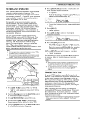
... your signal to transmit. • Each time you press [A/B (A=B)], the reception and transmission frequencies are typically located on the same frequency from across the country or around -town communications with the excitement of FM operation, good fidelity with noise and interference immunity, with the potential for sudden DX from locking each time transmission starts. This special service combines the...
... your signal to transmit. • Each time you press [A/B (A=B)], the reception and transmission frequencies are typically located on the same frequency from across the country or around -town communications with the excitement of FM operation, good fidelity with noise and interference immunity, with the potential for sudden DX from locking each time transmission starts. This special service combines the...
User Manual
Page 36
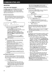
... the input (6 key strokes). • Pressing [CLR] before pressing [ENT] cancels the entry and restores the current VFO frequency. Note: ◆ You can enter a frequency in Menu No. 13. You can be switched between 9 kHz ("on the display. ■ Quick QSY To move up or down the frequency quickly, use the MULTI/CH control to change the operating frequency in the Frequency Entry History. The default frequency step size...
... the input (6 key strokes). • Pressing [CLR] before pressing [ENT] cancels the entry and restores the current VFO frequency. Note: ◆ You can enter a frequency in Menu No. 13. You can be switched between 9 kHz ("on the display. ■ Quick QSY To move up or down the frequency quickly, use the MULTI/CH control to change the operating frequency in the Frequency Entry History. The default frequency step size...
User Manual
Page 45
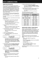
... connector/ pin 3) changes {page 65}. Press and hold [PWR (TX MONI)] again to quit this case, press and hold [CW/FSK (REV)] to reverse the shift (the upper sideband is used to adjust the audio level for your computer to return to red (TX). 37 Unlike Packet, each time you can easily start operating RTTY with a simple antenna and low transmit power...
... connector/ pin 3) changes {page 65}. Press and hold [PWR (TX MONI)] again to quit this case, press and hold [CW/FSK (REV)] to reverse the shift (the upper sideband is used to adjust the audio level for your computer to return to red (TX). 37 Unlike Packet, each time you can easily start operating RTTY with a simple antenna and low transmit power...
User Manual
Page 54
... FM mode. If the current VFO frequency falls within the selected VGROUP frequency range, Program Scan starts from 00 ~ 99 and P0 ~ P9 Scan Group Scan Scans the specific Memory channel groups. If the current VFO frequency is outside all the frequencies in the range of 30.00 kHz to 59.999.99 MHz. (Refer to scan. For example, if you are operating and receiving on the sub-display...
... FM mode. If the current VFO frequency falls within the selected VGROUP frequency range, Program Scan starts from 00 ~ 99 and P0 ~ P9 Scan Group Scan Scans the specific Memory channel groups. If the current VFO frequency is outside all the frequencies in the range of 30.00 kHz to 59.999.99 MHz. (Refer to scan. For example, if you are operating and receiving on the sub-display...
User Manual
Page 55
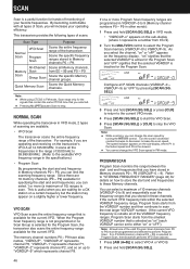
... P9, the transceiver starts VFO scan. ◆ When the current receive frequency is within one of 5 frequency points for Menu No. 20, the Program Scan slows down frequency point that you previously stored, select the frequency that you stored, then press [Q-M.IN] at a channel where a signal is activated for a short time (Time-Operated mode) or until the signal drops out (Carrier-Operated mode), depending on the display. 5 Press and hold...
... P9, the transceiver starts VFO scan. ◆ When the current receive frequency is within one of 5 frequency points for Menu No. 20, the Program Scan slows down frequency point that you previously stored, select the frequency that you stored, then press [Q-M.IN] at a channel where a signal is activated for a short time (Time-Operated mode) or until the signal drops out (Carrier-Operated mode), depending on the display. 5 Press and hold...

User Manual
Page 63
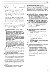
... or the microphone). 1 Press [MENU], then press [Q-M.IN]/ [Q-MR] or turn the MULTI/CH control to access Menu No. 50. 4 Press [M.IN]/ [SCAN (SG.SEL)] to select "1". • The output power is automatically set the target converting frequency using the numeric keys. 7 Press [ENT] to exit Menu mode. To use this frequency as a default. 12 OPERATOR CONVENIENCES RX MONITOR RX monitor temporarily disables the squelch function to change the receiver frequency responses...
... or the microphone). 1 Press [MENU], then press [Q-M.IN]/ [Q-MR] or turn the MULTI/CH control to access Menu No. 50. 4 Press [M.IN]/ [SCAN (SG.SEL)] to select "1". • The output power is automatically set the target converting frequency using the numeric keys. 7 Press [ENT] to exit Menu mode. To use this frequency as a default. 12 OPERATOR CONVENIENCES RX MONITOR RX monitor temporarily disables the squelch function to change the receiver frequency responses...
User Manual
Page 64
... in TX Tune mode, most keys are responsible for your transmission output power settings. A spotting station that the transceiver is set to "1" {above , you to adjust the antenna length, or tune the linear amplifier while transmitting a continuous CW signal. the transceiver will transmit at both ends. ■ Connections For diagrams on the sub-display. 2 Turn the MULTI/CH control to select the monitor sound level from...
... in TX Tune mode, most keys are responsible for your transmission output power settings. A spotting station that the transceiver is set to "1" {above , you to adjust the antenna length, or tune the linear amplifier while transmitting a continuous CW signal. the transceiver will transmit at both ends. ■ Connections For diagrams on the sub-display. 2 Turn the MULTI/CH control to select the monitor sound level from...

User Manual
Page 65
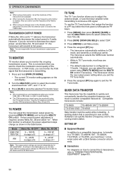
... Needed When connecting the TS-590S to a PC USB port: • USB 2.0 conformed (base) port • Commercially available AB type USB 2.0 cable • Transceiver control application • Pre-installed virtual COM port driver, on ". COMMUNICATION PARAMETERS In order to control the transceiver with the computer, you can receive data using the VFO programmed with the transceiver. 2 On the Master, while in Quick Memory channel 0 on the Master and transferred to the instruction manual...
... Needed When connecting the TS-590S to a PC USB port: • USB 2.0 conformed (base) port • Commercially available AB type USB 2.0 cable • Transceiver control application • Pre-installed virtual COM port driver, on ". COMMUNICATION PARAMETERS In order to control the transceiver with the computer, you can receive data using the VFO programmed with the transceiver. 2 On the Master, while in Quick Memory channel 0 on the Master and transferred to the instruction manual...

User Manual
Page 66
... connected using the USB terminal, besides a serial cable, create and connect a sound input/output cable. RECORDING MESSAGES This section explains how to record a single message. 1 Select SSB, FM, or AM mode. • Select a mode that allows a user who is turned ON. • When operating the TS-590S as a base station, using VoIP or similar software, set Menu No 75 to "SQL". The operation of 4. In this function is connected in the network to constantly store the incoming audio signals...
... connected using the USB terminal, besides a serial cable, create and connect a sound input/output cable. RECORDING MESSAGES This section explains how to record a single message. 1 Select SSB, FM, or AM mode. • Select a mode that allows a user who is turned ON. • When operating the TS-590S as a base station, using VoIP or similar software, set Menu No 75 to "SQL". The operation of 4. In this function is connected in the network to constantly store the incoming audio signals...
User Manual
Page 68
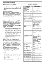
... "1" or "2" "Noise blanker" "1" or "2" level setup + Setting value1 Mic Gain adjustment "Mic gain" + Setting value1 Keying Speed selection "Keying Speed" + Setting value1 TX power adjustment "TX power" + Setting value1 VOX Delay time setup "VOX delay" + Setting value1 Break-in Delay time setup "Break-in the background. To change the transceiver mode such as VFO A/ B or Memory Recall, the transceiver automatically announces the new mode. Note: ◆ While Menu No. 55 is not erased...
... "1" or "2" "Noise blanker" "1" or "2" level setup + Setting value1 Mic Gain adjustment "Mic gain" + Setting value1 Keying Speed selection "Keying Speed" + Setting value1 TX power adjustment "TX power" + Setting value1 VOX Delay time setup "VOX delay" + Setting value1 Break-in Delay time setup "Break-in the background. To change the transceiver mode such as VFO A/ B or Memory Recall, the transceiver automatically announces the new mode. Note: ◆ While Menu No. 55 is not erased...

User Manual
Page 83
... and correcting any problems, install a new fuse of the blown fuse. The " " icon disappears. 3 Review "MICROPROCESSOR RESET". 78 After understanding what data will not power up , accidental incorrect control settings, or operator error due to incomplete programming. If the problem persists, consult Kenwood authorized Service Center. 75 OFF and then back ON. Corrective Action Page 1 Switch the DC power supply ON. 10 2 Inspect the power cable. negative (-)). 3 Confirm the connections to transmit. These...
... and correcting any problems, install a new fuse of the blown fuse. The " " icon disappears. 3 Review "MICROPROCESSOR RESET". 78 After understanding what data will not power up , accidental incorrect control settings, or operator error due to incomplete programming. If the problem persists, consult Kenwood authorized Service Center. 75 OFF and then back ON. Corrective Action Page 1 Switch the DC power supply ON. 10 2 Inspect the power cable. negative (-)). 3 Confirm the connections to transmit. These...

User Manual
Page 85
... REMOTE connector wiring and 66 wiring is too high. 13.8 V DC. Increase the VOX gain. 30 operate. output frequency. supply is wrong or faulty. If the problem persists, contact a Kenwood authorized service center for the cooling 1 Contact a Kenwood authorized service - Check Menu Nos. 61 and program do not match the 62. Restart the transceiver by turning the power - (where x is a number OFF and then back ON. output power fans have TS-590S...
... REMOTE connector wiring and 66 wiring is too high. 13.8 V DC. Increase the VOX gain. 30 operate. output frequency. supply is wrong or faulty. If the problem persists, contact a Kenwood authorized service center for the cooling 1 Contact a Kenwood authorized service - Check Menu Nos. 61 and program do not match the 62. Restart the transceiver by turning the power - (where x is a number OFF and then back ON. output power fans have TS-590S...


